CS01-LB -- LoRaWAN 4 Channels Current Sensor Converter User Manual

Table of Contents:
- 1. Introduction
- 2. Configure the CS01-LB to connect to LoRaWAN network
- 2.1 How it works
- 2.2 Quick Guide to Connect to LoRaWAN Network Server (OTAA)
- 2.3 Registration Information
- 2.4 Registering with The Things Stack
- 2.3 Device Status, FPort=5
- 2.4 Working Mode & Uplink Payload
- 2.5 Payload Formatter
- 2.6 Datalog Feature
- 2.7 Frequency Plans
- 2.8 Firmware Change Log
- 2.9 Integrate with IoT Platforms
- 3. Configure CS01-LB
- 3.1 Configure Methods
- 3.2 General Commands
- 3.3 Commands Specially Designed for CS01-LB
- 3.3.1 Set Uplink Transmit Interval
- 3.3.2 Get Device Status
- 3.3.3 Get Data
- 3.3.4 Set Interrupt Mode
- 3.3.5 Set Power Output Duration
- 3.3.6 Set Working Mode
- 3.3.7 Set the Alarm Threshold
- 3.3.8 Set Alarm Interval
- 3.3.9 Set enable or disable of the measurement channel
- 3.3.10 Set the current proportion parameter (Since V1.2)
- 3.3.11 Set current resolution (Since V1.2)
- 4. Use Cases
- 5. Battery & Power Consumption
- 6. OTA Firmware update
- 7. FAQ
- 8. Troubleshooting
- 9. Ordering Information
- 10. Packaging Information
- 11. Support
1. Introduction
1.1 What is the LoRaWAN 4 Channel Current Sensor Converter
The Dragino CS01-LB is a LoRaWAN 4-channel current sensor converter designed to transmit readings from current sensors to an IoT platform via a LoRaWAN network. This device is ideal for monitoring machine operating conditions and analyzing power consumption trends.
The CS01-LB can support up to four detachable current sensors, which can be swapped for sensors with different measurement scales as needed. It features BLE configuration and wireless OTA updates, simplifying setup and maintenance for users.
Powered by an 8500mAh Li-SOCI2 battery, the CS01-LB is engineered for long-term usage, lasting several years under typical operating conditions.
Each unit comes pre-loaded with unique keys for LoRaWAN registration. By registering these keys with a local LoRaWAN network server, the CS01-LB can automatically connect once powered on.
1.2 Features
- LoRaWAN 1.0.3 Class A
- Supported Bands: CN470, EU433, KR920, US915, EU868, AS923, AU915, IN865
- Ultra-low power consumption
- Supports up to 4 current sensors
- Compatible with various current sensor ratios: 50A, 100A, etc.
- Monitors machine operating status
- Analyzes power consumption trends
- Provides current alarms
- Supports Bluetooth v5.1 and LoRaWAN remote configuration
- Supports wireless OTA firmware updates
- Periodic uplink transmissions
- Downlink capability to modify configurations
- 8500mAh Li/SOCl2 battery
1.3 Current Sensor Specification
The current sensors listed below are not shipped with the CS01-LB. You need to order them separately.
| Model | Photo | Specification | Dimension(Unit:mm±0.5) |
|---|---|---|---|
| SCT013G-D-100 |
| * Split core current transformer * Spec: 100A/50mA * φ16mm Aperture |
|
| SCT024-300 |  | * Split core current transformer * Spec: 300A/50mA * φ24mm Aperture |
|
| SCT036-600 |
| * Split core current transformer * Spec: 600A/50mA * φ36mm Aperture |
|


1.4 Specification
Common DC Characteristics:
- Supply Voltage: Built-in battery, 2.5V ~ 3.6V
- Operating Temperature: -40°C ~ 85°C
LoRa Specification:
- Frequency Range, Band 1 (HF): 862 ~ 1020 MHz
- Maximum RF Output: +22 dBm constant
- RX Sensitivity: Down to -139 dBm
- Excellent blocking immunity
Battery:
- Type: Li/SOCl2 non-rechargeable battery
- Capacity: 8500mAh
- Self-Discharge: <1% per year @ 25°C
- Maximum Continuous Current: 130mA
- Maximum Boost Current: 2A for 1 second
Power Consumption:
- Sleep Mode: 5µA @ 3.3V
- LoRa Transmit Mode: 125mA @ 20dBm, 82mA @ 14dBm
1.5 Deep Sleep Mode and Working Mode
Deep Sleep Mode: The sensor does not perform any LoRaWAN activity. This mode is intended for storage and shipping to conserve battery life.
Working Mode: In this mode, the sensor operates as a LoRaWAN sensor, joining the LoRaWAN network and transmitting data to the server. Between each sampling, transmission, and reception period, the sensor enters IDLE mode. In IDLE mode, the sensor consumes the same amount of power as in Deep Sleep mode.
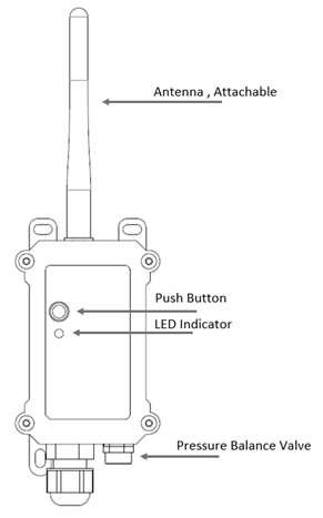
1.6 Button & LEDs
The CS01-LB has push button labelled as ACT and a LED indicator.
| Behavior on ACT | Function | Action |
|---|---|---|
 1 ~ 3s 1 ~ 3s | Send an uplink | If the sensor is already joined to the LoRaWAN network, it will send an uplink packet, and the Blue LED will blink once. Meanwhile, the BLE module will be activated, allowing the user to connect via BLE to configure the device. |
 >3s >3s | Active Device | The Green LED will blink rapidly five times, and the device will enter OTAA mode for 3 seconds before starting to join the LoRaWAN network. The Green LED will remain solid for 5 seconds once the device successfully joins the network. After the sensor becomes active, the BLE module will be enabled, allowing the user to connect via BLE to configure the device, regardless of whether it has joined the LoRaWAN network. |
 x5 x5 | Deactivate Device | The Red LED will stay solid for 5 seconds, indicating that the device is in Deep Sleep Mode. |
1.7 BLE Connection
CS01-LB supports BLE (Bluetooth Low Energy) remote configuration.
BLE can be used to configure the sensor's parameters or view the console output from the sensor. BLE will only be activated in the following cases:
- Pressing the button to send an uplink
- Pressing the button to activate the device
- Device power on or reset
If there is no activity or connection via BLE within 60 seconds, the sensor will shut down the BLE module to enter low power mode.
1.8 Pin Definitions
The CS01-LB has the following pin definitions.

1.8.1 SW2 Jumper (Define UART level to external Sensor)
SW2 defines the voltage level of the BOARD_RX and BOARD_TX pins. It should match the external sensor's voltage level.
1.9 Mechanical Drawings
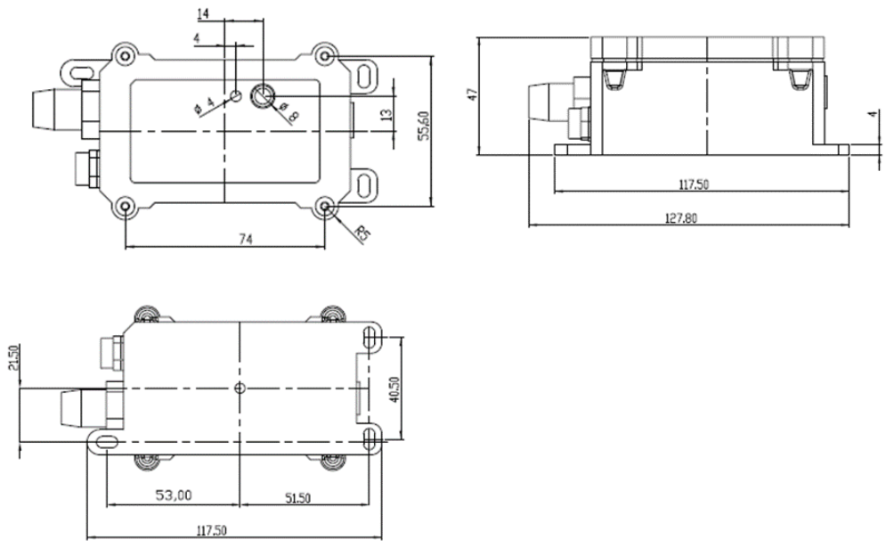
100A:

300A:

600A:

2. Configure the CS01-LB to connect to LoRaWAN network
2.1 How it works
The CS01-LB is configured by default as a LoRaWAN OTAA Class A device. It comes with a pre-assigned DevEUI, AppEUI, and AppKey to enable joining a LoRaWAN network using OTAA. These same DevEUI, AppEUI, and AppKey values must be registered with the LoRaWAN Network Server you plan to use.
To connect a local LoRaWAN network, you need to input the OTAA keys in the LoRaWAN IoT server and press the button to activate the CS01-LB. It will automatically join the network via OTAA and start to send the sensor value. The default uplink interval is 20 minutes.
Then press the ACT button for more than 3 seconds to activate the CS01-LB. It will automatically join the network via OTAA and begin sending sensor values. The default uplink interval is 20 minutes.
" class="xwiki-metadata-container">The CS01-LB does not include a current sensor. The user needs to obtain the current sensor separately and attach it to the CS01-LB for measurement.
2.2 Quick Guide to Connect to LoRaWAN Network Server (OTAA)
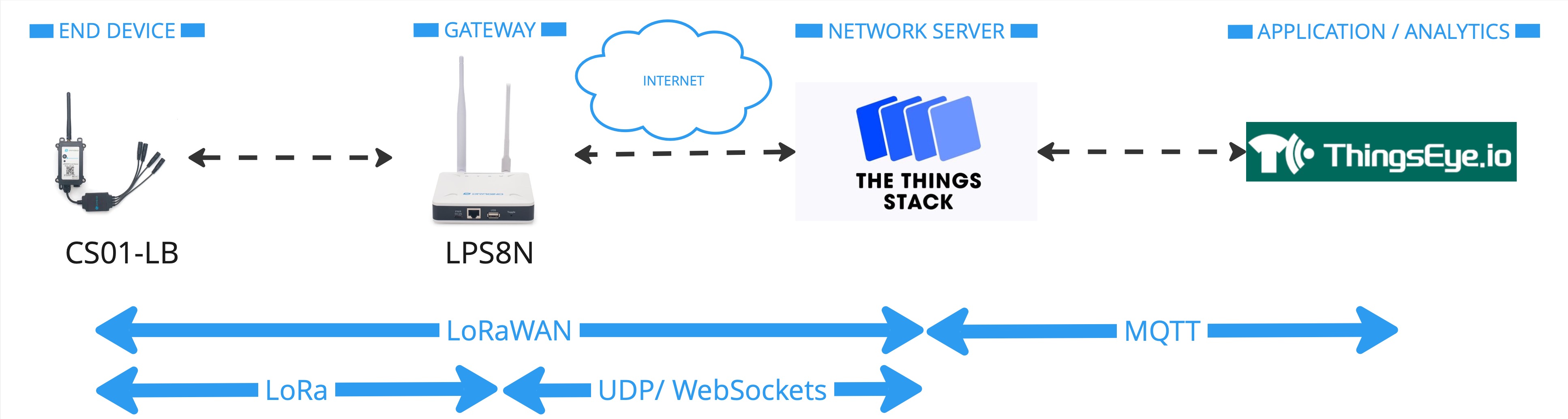
The following figure shows how the CS01-LB connects to The Things Stack. The CB01-LB sends messages (uplinks) to The Things Stack via a LoRaWAN gateway (e.g., Dragino LPS8N) and can also receive messages (downlinks) from The Things Stack. The Things Stack can be integrated with ThingsEye, allowing it to forward uplinks to ThingsEye. ThingsEye is an IoT platform used for visualizing and analyzing sensor data. You can also send downlinks from ThingsEye (via The Things Stack) to the CS01-LB.
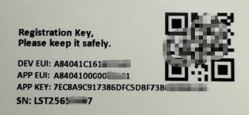
2.3 Registration Information
Each CS01-LB is shipped with registration information, including a unique DevEUI, AppEUI, and AppKey.
2.4 Registering with The Things Stack
The CS01-LB can be registered with The Things Stack for OTAA activation. It currently supports only manual registration with The Things Stack. The following steps explain how to register the CS01-LB with The Things Stack.
2.4.1 Create an Application
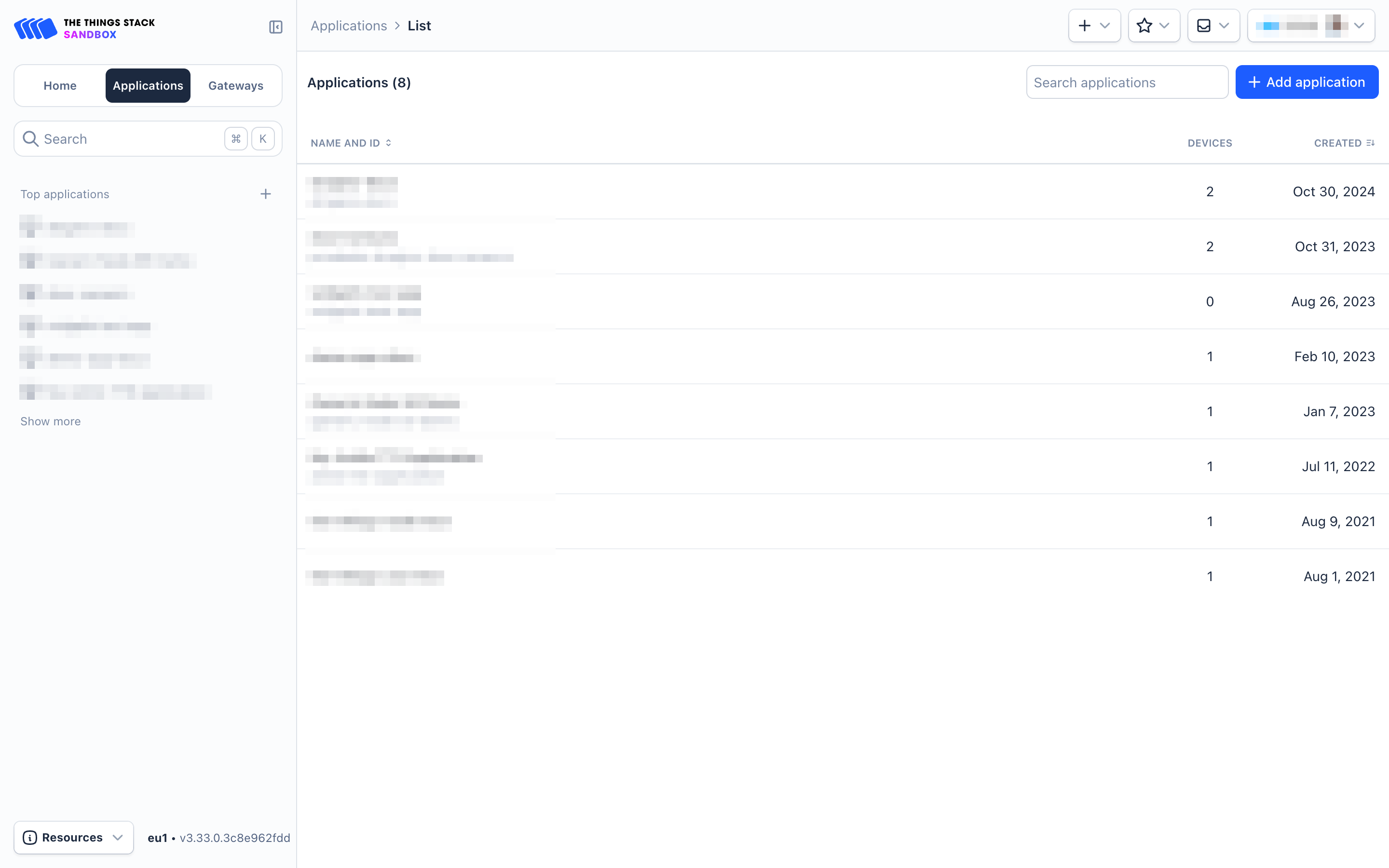
- Sign up for a free account with The Things Stack Sandbox if you do not have one yet.
- Log in to your The Things Stack account.
- Create an application with The Things Stack if you do not have one yet.
- On the left navigation, click Applications.
- Then click + Add Application button.
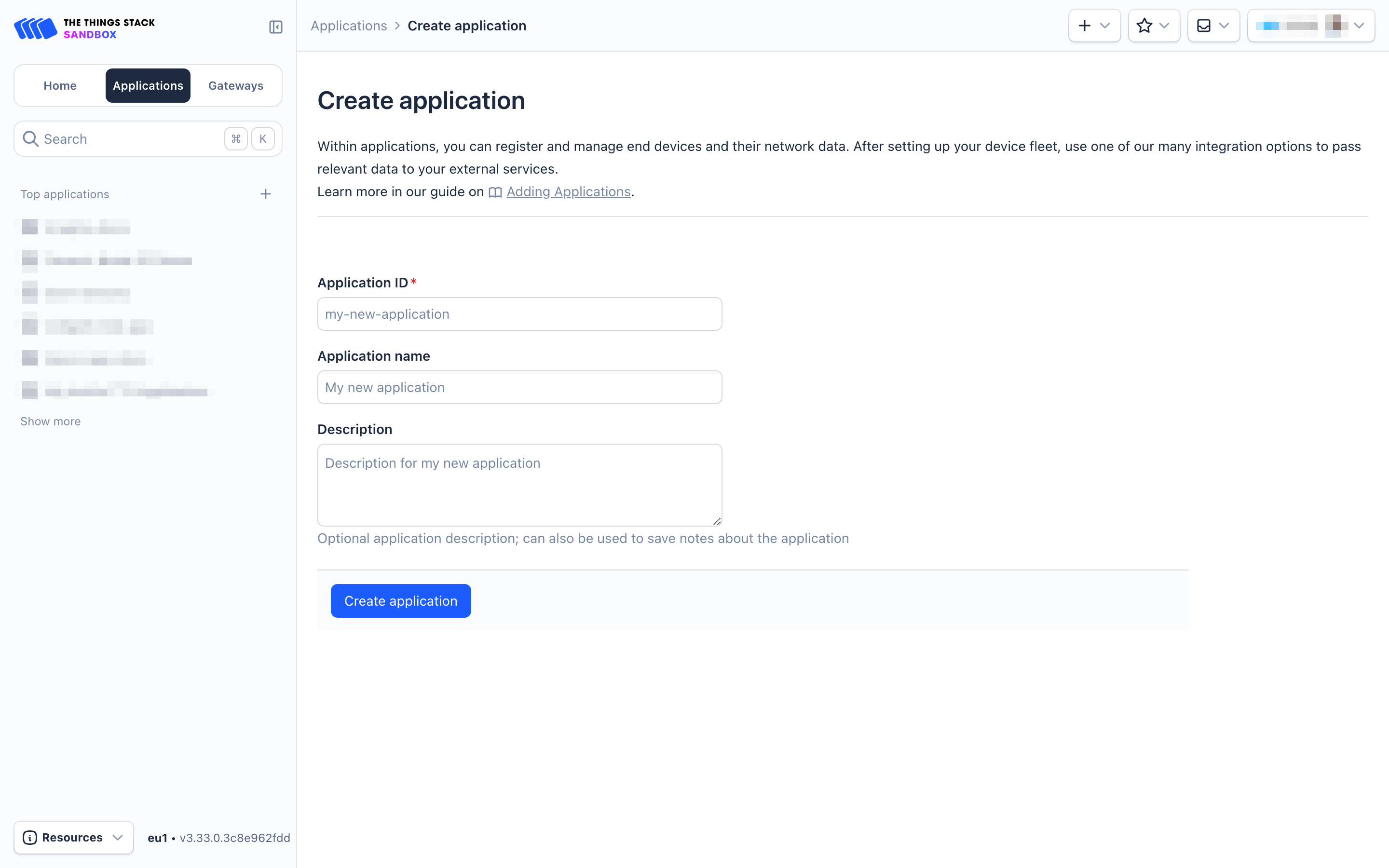
- On the Create Application page, configure the following:
- Application ID: Provide a unique identification for your application within The Things Stack.
- Application name: (optional) Provide a descriptive name.
- Description: (optional) Provide a description.
- Click on Create application button.
2.4.2 Register CS01-LB
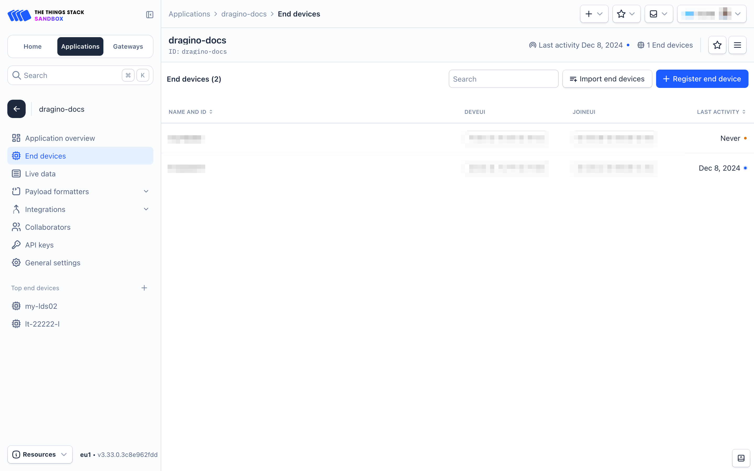
- Go to your application's page and click on the End devices in the left menu.
- On the End devices page, click on + Register end device
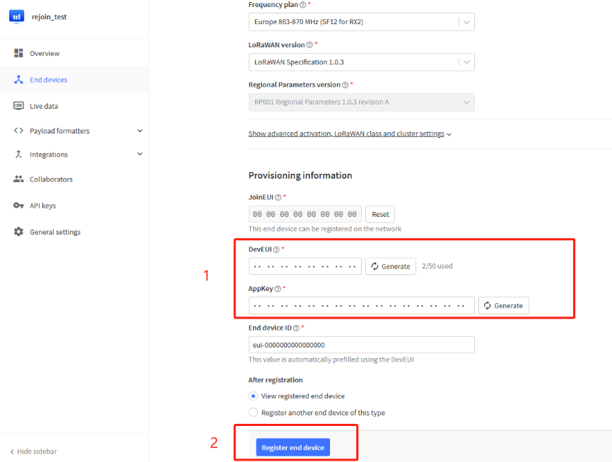
On the Register end device page:
- Select the option Enter end device specifies manually under Input method.
- Frequency plan : Select the Frequency plan that matches your device.
- LoRaWAN version: LoRaWAN Specification 1.0.3
- JoinEUI : Enter the AppEUI here (see the registration information sticker). Then click Confirm button.
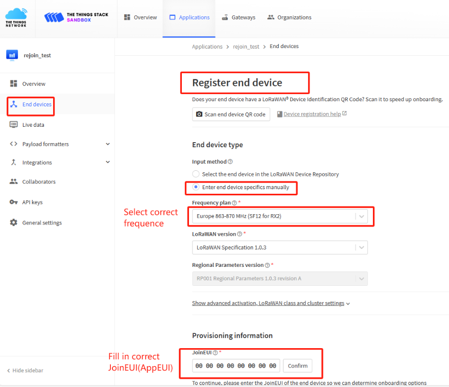
- DevEUI : Enter the DevEUI here (see the registration information sticker).
- AppKey : Enter the AppKey here (see the registration information sticker).
- End device ID : Enter a unique name for your CS01-LB within this application.
- Under After registration, select the View registered end device option.
- Click Register end device button.
Press the ACT button for 5 seconds to activate the CS01-LB.
The Green LED will blink rapidly 5 times, and the device will enter OTAA mode for 3 seconds. Then, it will start joining the LoRaWAN network. The Green LED will remain solid for 5 seconds after successfully joining the network.
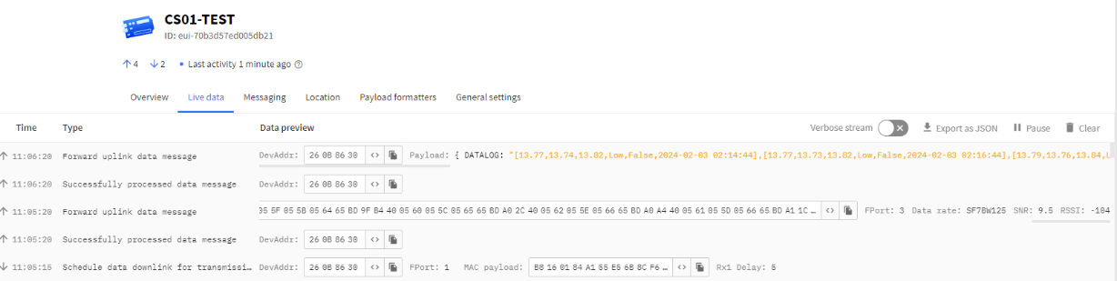
Once the device has joined successfully, it will start uploading messages to The Things Stack, and you can see the messages in the Live data panel.
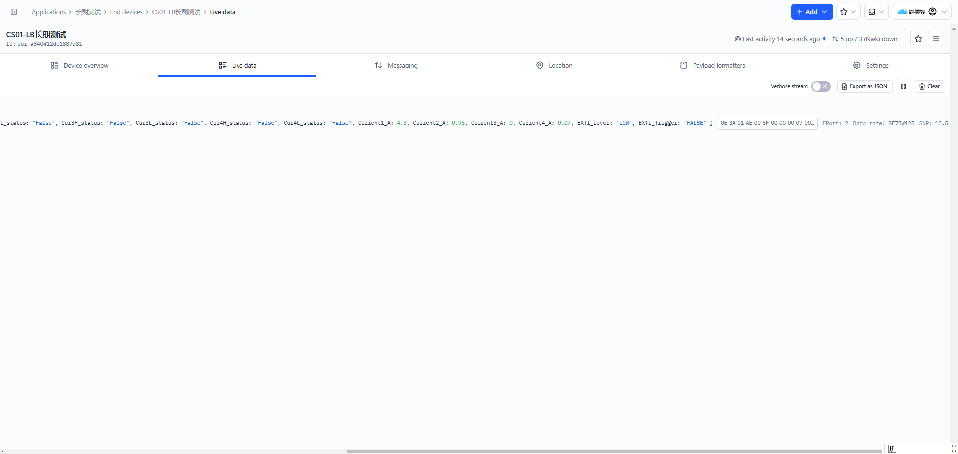
2.3 Device Status, FPort=5
You can use the downlink command, 0x26 01, to request the CS01-LB to send device configuration details, including the device configuration status. The CS01-LB will uplink a payload via FPort=5 to the LoRaWAN Network Server.
The payload format is as follows:
| Device Status (FPort=5) | |||||
| Size (bytes) | 1 | 2 | 1 | 1 | 2 |
| Value | Sensor Model | Firmware Version | Frequency Band | Sub-band | BAT |
Example: Consider the uplink payload 33 01 00 01 FF 0C 60.
The following values can be extracted from the above payload.
Sensor Model (1 byte): For CS01-LB, this value is 0x33
Firmware Version (2 bytes): 0x0100, Means: v1.0.0 version
Frequency Band (1 byte):
- 0x01: EU868
- 0x02: US915
- 0x03: IN865
- 0x04: AU915
- 0x05: KZ865
- 0x06: RU864
- 0x07: AS923
- 0x08: AS923-1
- 0x09: AS923-2
- 0x0a: AS923-3
- 0x0b: CN470
- 0x0c: EU433
- 0x0d: KR920
- 0x0e: MA869
Sub-Band (1 byte):
AU915 and US915:value 0x00 ~ 0x08
CN470: value 0x0B ~ 0x0C
Other Bands: Always 0x00
Battery Info (2 bytes):
Check the battery voltage.
0x0C 60 = 3168 mV
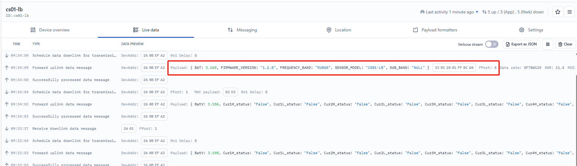
2.4 Working Mode & Uplink Payload
2.4.1 MOD=1(General Acquisition Mode), FPort=2
Note: The AT+CCAL=0,0,0,0 command must be set when the v1.0 version firmware for the first time, otherwise inaccurate current readings may occur.
MOD=1 is the default mode. The end node will uplink the real-time current sensor value in two case:
- At each TDC interval.
- When an alarm is triggered based on the AT+CALARM configure.
Uplink packets use FPort=2.
Size(bytes) | 2 | 2 | 2 | 2 | 2 | 1 |
|---|---|---|---|---|---|---|
| Value | Battery Info&Interrupt flag & Interrupt Level | Current channel 1 | Current channel 2 | Current channel 3 | Current channel 4 | Alarm_status* |
Alarm_status is a combination of Cur1L_status, Cur1H_status, Cur2L_status, Cur2H_status, Cur3L_status, Cur3H_status, Cur4L_status and Cur4H_status.
It consists of a total of 1 byte, as shown below:
Bit 7 | Bit 6 | Bit 5 | Bit 4 | Bit 3 | Bit 2 | Bit 1 | Bit 0 |
|---|---|---|---|---|---|---|---|
Cur1L | Cur1H | Cur2L | Cur2H | Cur3L | Cur3H | Cur4L | Cur4H |
Example: Consider the payload, 0C 7E 05 86 05 7E 05 8D 00 00 00.
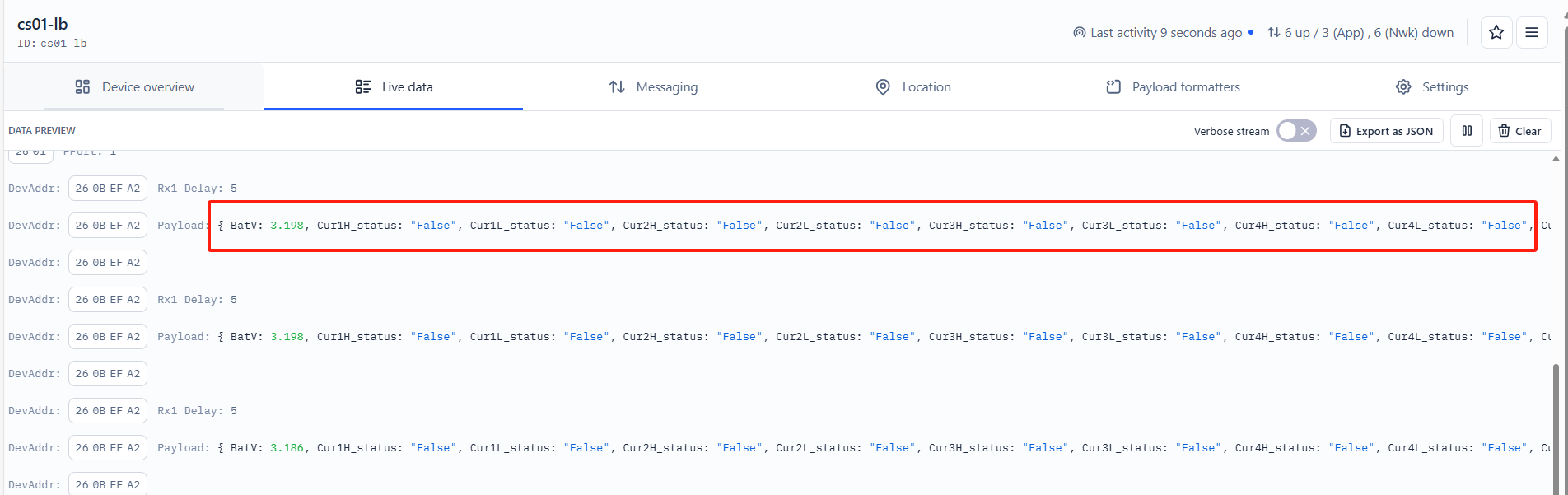
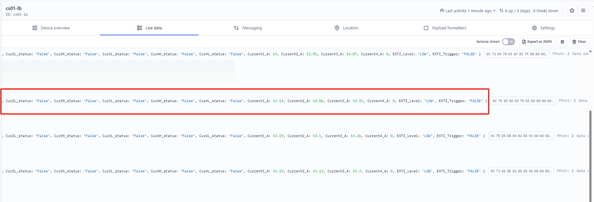
0C 7E 05 86 05 7E 05 8D 00 00 00
Battery Info
Check the battery voltage for CS01-LB/LS.
In this example:
0x0C7E&0x3FFFF = 3198mV
Some other examples:
Ex1: 0x0B45&0x3FFF = 2885mV
Ex2: 0x0B49&0x3FFF = 2889mV
Interrupt Flag & Interrupt Level
This data field indicates whether this packet was generated by an interrupt or not. Click here for the hardware and software setup.
Note: The interrupt pin refers to the GPIO_EXTI pin on the screw terminal. See the pin mapping.
In this example:
0x0C&0x80>>15 =0x00 : Normal uplink packet
0x0C&0x40>>14 =0x00 : Interrupt pin low level
Some other examples:
If byte[0]&0x80>>15=0x00 : Normal uplink packet.
If byte[0]&0x80>>15=0x01 : Interrupt uplink Packet.
If byte[0]&0x40>>14=0x00 : Interrupt pin low level.
If byte[0]&0x40>>14=0x01 : Interrupt pin high level.
Current channel 1:
Channel 1 for measuring AC current with a resolution of 0.01A.
Example: 0x0586 = 1414/100 = 14.14A
Current channel 2:
Channel 2 for measuring AC current with a resolution of 0.01A.
Example: 0x057E = 1406/100 =14.06A
Current channel 3:
Channel 3 for measuring AC current with a resolution of 0.01A.
Example: 0x058D = 1421/100 = 14.21A
Current channel 4:
Channel 4 for measuring AC current with a resolution of 0.01A.
Example: 0x0000 = 000/100 = 0A
Cur1L_status:
When setting the current threshold alarm for channel 1, this flag is True if the current is lower than the set threshold; otherwise, it is False.
In this example, Cur1L_status is false because the bit 7 is 0.
Cur1H_status:
When setting the current threshold alarm for channel 1, this flag is True if the current is higher than the set threshold; otherwise, it is False.
In this example, Cur1H_status is false because the bit 6 is 0.
Cur2L_status:
When setting the current threshold alarm for channel 2, this flag is True if the current is lower than the set threshold; otherwise, it is False.
In this example, Cur2L_status is false because the bit 5 is 0.
Cur2H_status:
When setting the current threshold alarm for channel 2, this flag is True if the current is higher than the set threshold; otherwise, it is False.
In this example, Cur1H_status is false because the bit 4 is 0.
Cur3L_status:
When setting the current threshold alarm for channel 3, this flag is True if the current is lower than the set threshold; otherwise, it is False.
In this example, Cur1L_status is false because the bit 3 is 0.
Cur3H_status:
When setting the current threshold alarm for channel 3, this flag is True if the current is higher than the set threshold; otherwise, it is False.
In this example, Cur1H_status is false because the bit 2 is 0.
Cur4L_status:
When setting the current threshold alarm for channel 4, this flag is True if the current is lower than the set threshold; otherwise, it is False.
In this example, Cur1L_status is false because the bit 1 is 0.
Cur4H_status:
When setting the current threshold alarm for channel 4, this flag is True if the current is higher than the set threshold; otherwise, it is False.
In this example, Cur1H_status is false because the bit 0 is 0.
2.4.2 MOD=2 (Continuous Sampling Mode), FPort=7
In Continuous Sampling Mode (AT+MOD=2, aa, bb), the CS01 will record the current sensor data at fixed intervals and later report multiple groups of data together to the IoT server.
Note: This mode has high power consumption. An external power supply might be needed. For more details, please check the power consumption section.
AT+MOD=2,aa,bb format:
- First Parameter set to 2: Sets the CS01-LB to work in Continuous Sampling Mode.
- aa : Sets the sampling interval (unit: seconds)
- bb : Defines how many groups of data will be uplinked together.
When CS01-LB is in Continuous Sampling Mode, the TDC time setting is disabled, and CS01-LB will send uplink once it finished the number of sampling define in "bb".
Example Command:AT+MOD=2,60,5
The CS01-LB will read data from 4 channels every 1 minute. After reading 5 groups, the CS01-LB will send an uplink. Therefore, the uplink interval is 5 minutes. Each uplink will include 5 groups of sensor values. Each group contains data from 4 channels. The payload for each uplink will include:
- Battery (2 bytes)
- Group 1 Sensor Value (8 bytes): The 4th most recent reading for Channel 1, Channel 2, Channel 3, and Channel 4
- Group 2 Sensor Value (8 bytes): The 3rd most recent reading for Channel 1, Channel 2, Channel 3, and Channel 4
- Group 3 Sensor Value (8 bytes): The 2nd most recent reading for Channel 1, Channel 2, Channel 3, and Channel 4
- Group 4 Sensor Value (8 bytes): The most recent reading for Channel 1, Channel 2, Channel 3, and Channel 4
- Group 5 Sensor Value (8 bytes): The current reading for Channel 1, Channel 2, Channel 3, and Channel 4
In total, the payload in this example is 42 bytes.
Note: Continuous Sampling Mode may generate a large payload, and the CS01-LB will select the appropriate DR to uplink the data. This might reduce the transmission distance.
Uplink packets use FPort=7.
Size(bytes) | 2 | Dynamic Length , Depending on how many groups | |||||
|---|---|---|---|---|---|---|---|
Value | BAT | Sensor value: Each 8 bytes represent a set of sensor values (the maximum is 30 groups). | |||||
Example: Consider the payload, 0C6604290422042E0000042D042604330000042C042604330000042F042804350000042E042704330000.
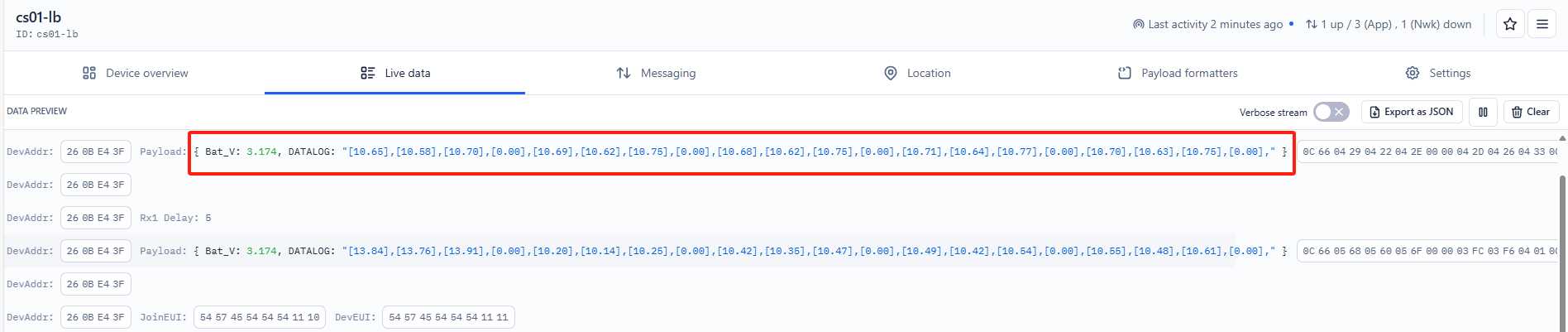
Battery voltage: 0x0C66&0x3FFFF = 3174 mV
2.5 Payload Formatter
Payload formatters convert hexadecimal payloads into human-readable data fields. The Things Stack supports payload formatters for decoding uplink and downlink payloads.
Dragino has written a payload formatter to decode uplink payloads, which is compatible with The Things Stack. The uplink payload formatter can be downloaded from this link (CS01-LB_v1.0_TTN_Decoder.txt):
https://github.com/dragino/dragino-end-node-decoder/tree/main/CS01-LB
- Select the CS01-LB from your application.
- Click on the Payload formatters tab.
- Click on the Uplink tab if it is not selected by default.
- Select Custom Javascript formatter from the Formatter type dropdown list.
- In the Formatter code text box, paste the uplink formatter code you copied from the above GitHub link.
- Click on the Save changes button.

2.6 Datalog Feature
Datalog Feature is to ensure IoT Server can get all sampling data from Sensor even if the LoRaWAN network is down. For each sampling, CS01-LB/LS will store the reading for future retrieving purposes.
2.6.1 How datalog works
CS01-LB/LSwill wait for ACK for every uplink, when there is no LoRaWAN network,CS01-LB/LS will mark these records with non-ack messages and store the sensor data, and it will send all messages (10s interval) after the network recovery.
a) CS01-LB/LS will do an ACK check for data records sending to make sure every data arrive server.
b) CS01-LB/LS will send data in CONFIRMED Mode, but CS01-LB/LS won't re-transmit the packet if it doesn't get ACK, it will just mark it as a NONE-ACK message. In a future uplink if CS01-LB/LS gets a ACK, CS01-LB/LS will consider there is a network connection and resend all NONE-ACK messages.
2.6.2 Enable Datalog
User need to make sure below two settings are enable to use datalog;
- SYNCMOD=1(Default) to enable sync time via LoRaWAN MAC command, click here (AT+SYNCMOD) for detailed instructions.
- PNACKMD=1 to enable datalog feature, click here (AT+PNACKMD) for detailed instructions.
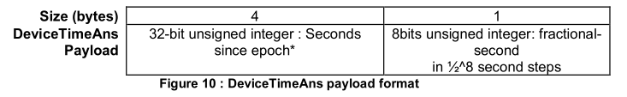
Once CS01-LB/LS Joined LoRaWAN network, it will send the MAC command (DeviceTimeReq) and the server will reply with (DeviceTimeAns) to send the current time to CS01-LB/LS. If CS01-LB/LS fails to get the time from the server, CS01-LB/LS will use the internal time and wait for next time request (AT+SYNCTDC to set the time request period, default is 10 days).
Note: LoRaWAN Server need to support LoRaWAN v1.0.3(MAC v1.0.3) or higher to support this MAC command feature, Chirpstack,TTN V3 v3 and loriot support but TTN V3 v2 doesn't support. If server doesn't support this command, it will through away uplink packet with this command, so user will lose the packet with time request for TTN V3 v2 if SYNCMOD=1.
2.6.3 Unix Timestamp
The CS01-LB uses the following Unix Timestamp:
You can get the Unix Timestamp from this link: https://www.epochconverter.com/ :
The following example shows how to convert the Unix Timestamp into hex number.
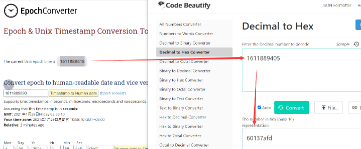
So, you can use AT+TIMESTAMP=1611889405 or downlink 3060137afd00 to set the current time as 2021 – Jan -- 29 Friday 03:03:25
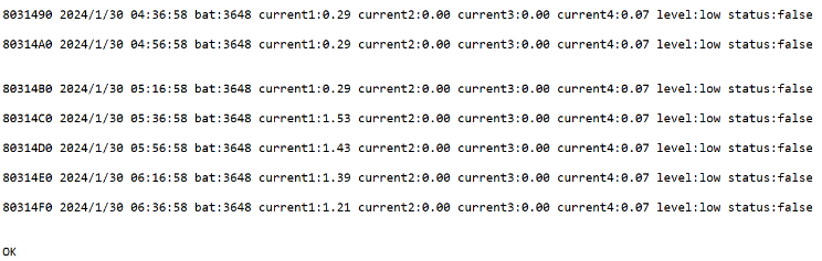
2.6.4 Datalog Uplink Payload (FPort=3)
The Datalog uplinks will use the following payload format.
Retrieval data payload:
Size(bytes) | 1 | 2 | 2 | 2 | 4 |
|---|---|---|---|---|---|
| Value | Interrupt flag & Interrupt_level
| Current1 | Current2 | Current3 | Unix TimeStamp |
Interrupt flag & Interrupt level :
Size(bit) | bit 7 | bit 6 | [bit 5:bit 2] | bit1 | bit0 |
|---|---|---|---|---|---|
| Value | NO ACK message
| Poll Message Flag | Reserve | interrupt level | interrupt flag |
No ACK Message: 1: This indicates that the payload is from an uplink message that did not receive an ACK from the server (for the PNACKMD=1 feature)
Poll Message Flag: 1: This indicates a poll message reply.
- Poll Message Flag is set to 1.
- The Poll Message Flag is set to 1. Each data entry is 11 bytes. To save airtime and battery, devices will send the maximum bytes allowed based on the current DR and frequency bands.
For example, in the US915 band, the maximum payload for different DR values is as follows:
a) DR0: Maximum is 11 bytes, so one data entry
b) DR1: Maximum is 53 bytes, so the device will upload 4 data entries (total 44 bytes)
c) DR2: Total payload includes 11 data entries
d) DR3: Total payload includes 22 data entries
If the device doesn't have any data at the polling time, it will uplink 11 bytes of zeros.
Example:
If the CS01-LB has the following data stored inside flash:
If you send the downlink command, 3165BD971865BDA5283C
Where:
- Start time: 65BD9718 = 23/05/24 03:30:41
- Stop time: 65BDA528 = 23/05/24 03:33:00
The CS01-LB will uplink this payload:
4005650562056A65BD974440055D0559056265BD97BC400562055E056765BD98344005640560056965BD98AC40056A0566056F65BD992440056A0566056F65BD999C4005680564056D65BD9A144005670563056C65BD9A8C4005680564056D65BD9B0440055F055E056765BD9B7C40055F055C056465BD9BF44005660562056B65BD9C6C400562055F056765BD9CE4400562055E056765BD9D5C40055C0558056165BD9DD4400560055C056565BD9E4C400561055D056665BD9EC44005650561056965BD9F3C40055F055B056465BD9FB4400560055C056565BDA02C400562055E056665BDA0A4400561055D056665BDA11C
Where the first 11 bytes is for the first entry:
40 05 65 05 62 05 6A 65 BD 97 44
Current1=0x0565/100=13.81
Current2=0x0562/100=13.78
Current3=0x056A/100=13.86
Interrupt flag & Interrupt_level=0x40 : This indicates a reply data sampling uplink message, with the interrupt level set to low and the interrupt flag set to false.
Unix time is 0x65BD9744=1706923844s=24/2/3 01:30:44
2.7 Frequency Plans
The CS01-LB uses OTAA mode and the frequency plans below by default. Each frequency band uses different firmware, and the user must update the firmware to the corresponding band for their country: See End Device Frequency Band for more information.
2.8 Firmware Change Log
The firmware can be download from this link: https://www.dropbox.com/scl/fo/cnnyz4ynebs3am96jvtv0/h?rlkey=4no594ssi0nzt2lc3irbkid9b&dl=0
2.9 Integrate with IoT Platforms
The Things Stack can be integrated with many IoT platforms, including ThingsEye and Datacake, for visualizing and analyzing data coming from the CS01-LB. Most of these IoT platforms also support sending downlinks to the CS01-LB.
2.9.1 Integrate with ThingsEye
The Things Stack application supports integration with ThingsEye.io. Once integrated, ThingsEye.io acts as an MQTT client for The Things Stack MQTT broker, allowing it to subscribe to upstream traffic and publish downlink traffic.
2.9.1.1 Configuring The Things Stack
We use The Things Stack Sandbox in this example. Of course, you can apply this example to any The Things Stack plan.
- In The Things Stack Sandbox, go to the Application for the LDS02 you added.
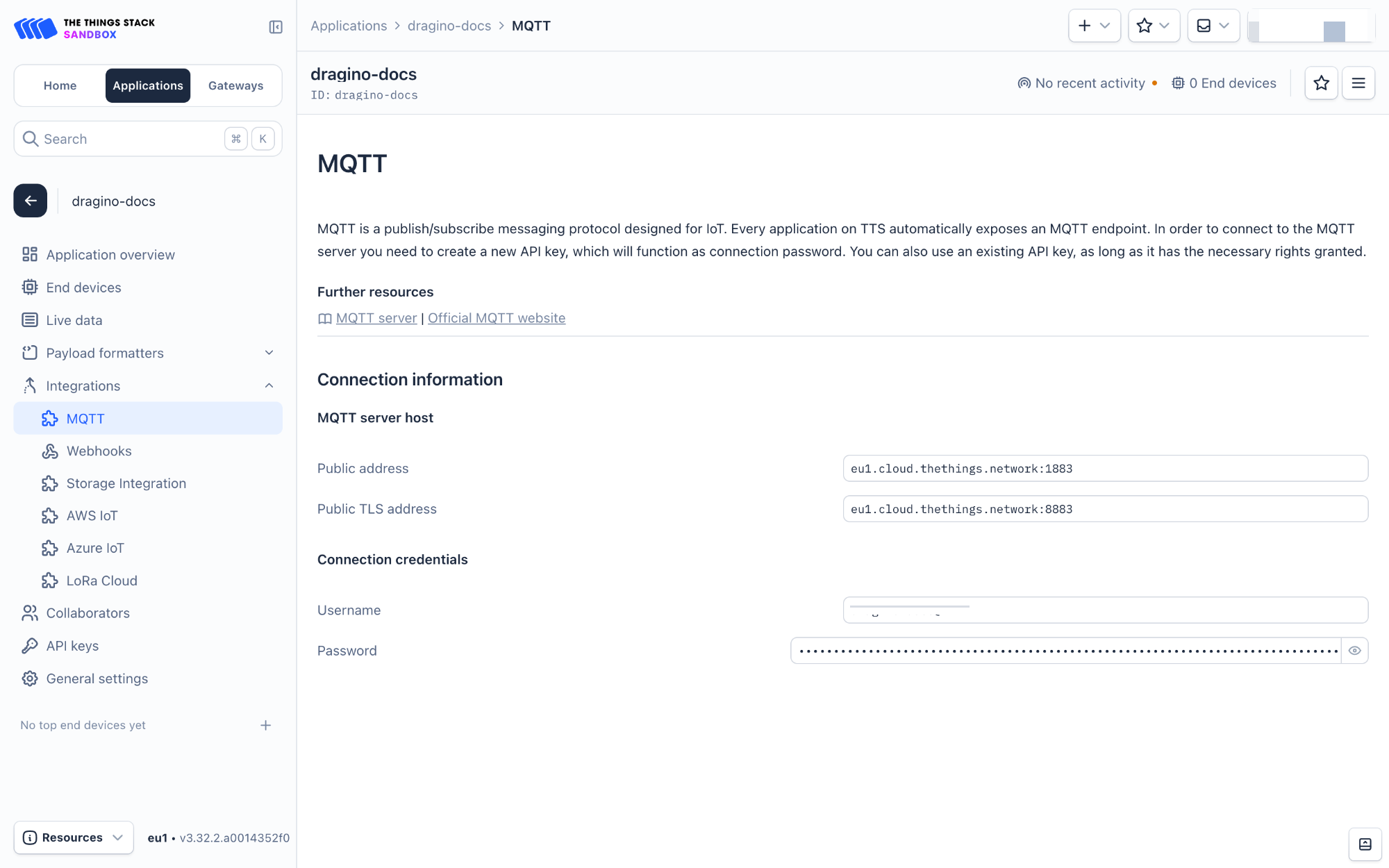
- Select MQTT under Integrations in the left menu.
- In the Connection information section, under Connection credentials, The Things Stack displays an auto-generated username. You can use it or provide a new one.
- Click the Generate new API key button to generate a password. You can view it by clicking on the visibility toggle/eye icon. The API key works as the password.
" class="xwiki-metadata-container">The username and password (API key) you created here are required in the next section.
2.9.1.2 Configuring ThingsEye.io
The ThingsEye.io IoT platform is not open for self-registration at the moment. If you are interested in testing the platform, please send your project information to admin@thingseye.io, and we will create an account for you.
- Login to your ThingsEye.io account.
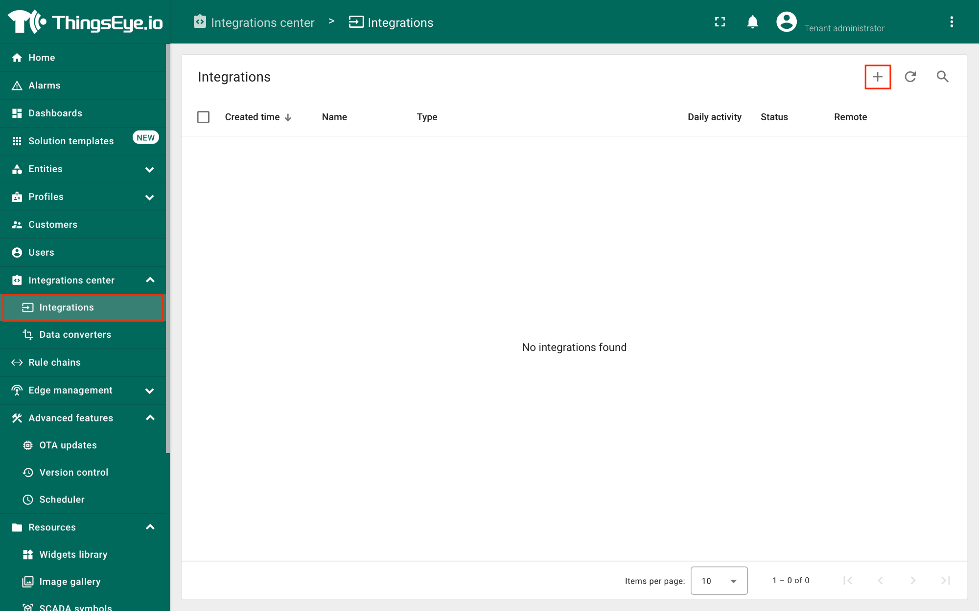
- Under the Integrations center, click Integrations.
- Click the Add integration button (the button with the + symbol).
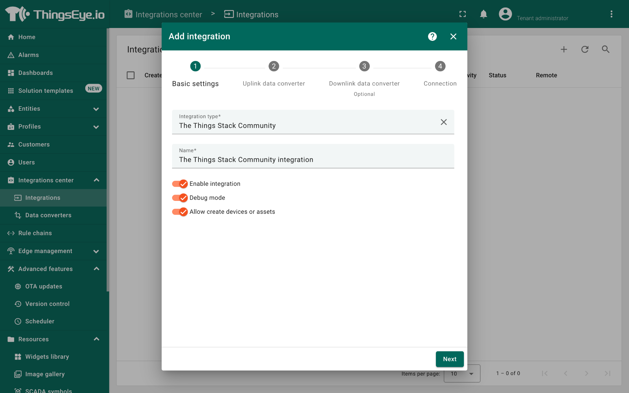
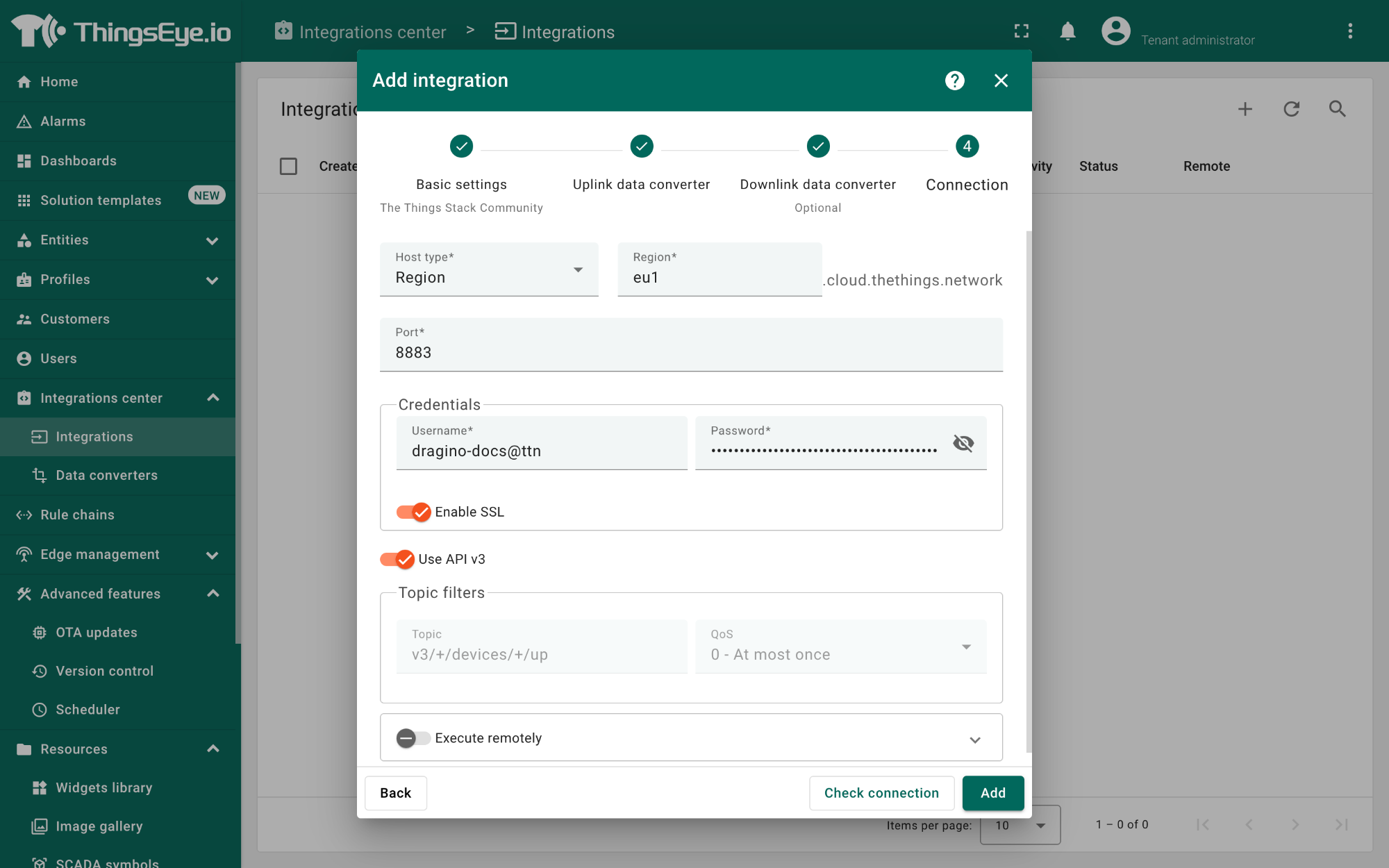
On the Add integration window, configure the following:
Basic settings:
- Select The Things Stack Community from the Integration type list.
- Enter a suitable name for your integration in the Name text box or keep the default name.
- Ensure the following options are turned on.
- Enable integration
- Debug mode
- Allow creating devices or assets
- Click the Next button. you will be navigated to the Uplink data converter tab.
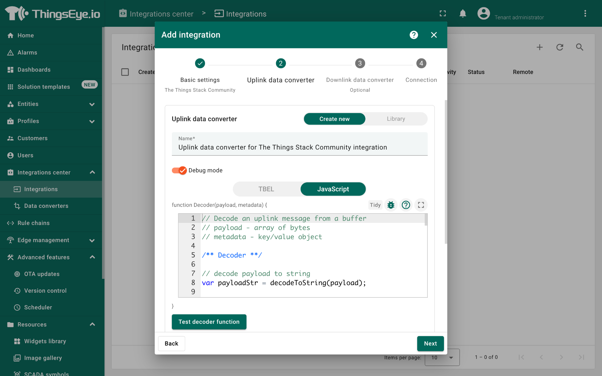
Uplink data converter:
- Click the Create new button if it is not selected by default.
- Enter a suitable name for the uplink data converter in the Name text box or keep the default name.
- Click the JavaScript button.
- Paste the uplink decoder function into the text area (first, delete the default code). The demo uplink decoder function can be found here.
- Click the Next button. You will be navigated to the Downlink data converter tab.
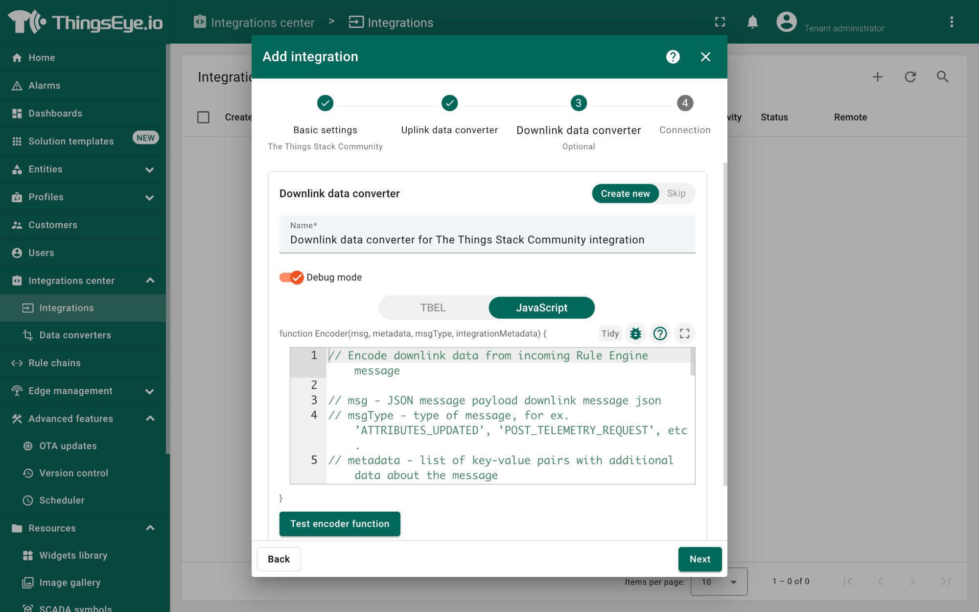
Downlink data converter (this is an optional step):
- Click the Create new button if it is not selected by default.
- Enter a suitable name for the downlink data converter in the Name text box or keep the default name.
- Click the JavaScript button.
- Paste the downlink decoder function into the text area (first, delete the default code). The demo downlink decoder function can be found here.
- Click the Next button. You will be navigated to the Connection tab.
Connection:
- Choose Region from the Host type.
- Enter the cluster of your The Things Stack in the Region textbox. You can find the cluster in the url (e.g., https://eu1.cloud.thethings.network/...).
- Enter the Username and Password of the MQTT integration in the Credentials section. The username and password can be found on the MQTT integration page of your The Things Stack account (see 2.9.1.1 Configuring The Things Stack).
- Click the Check connection button to test the connection. If the connection is successful, you will see the message saying Connected.
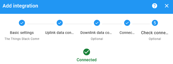
- Click the Add button.
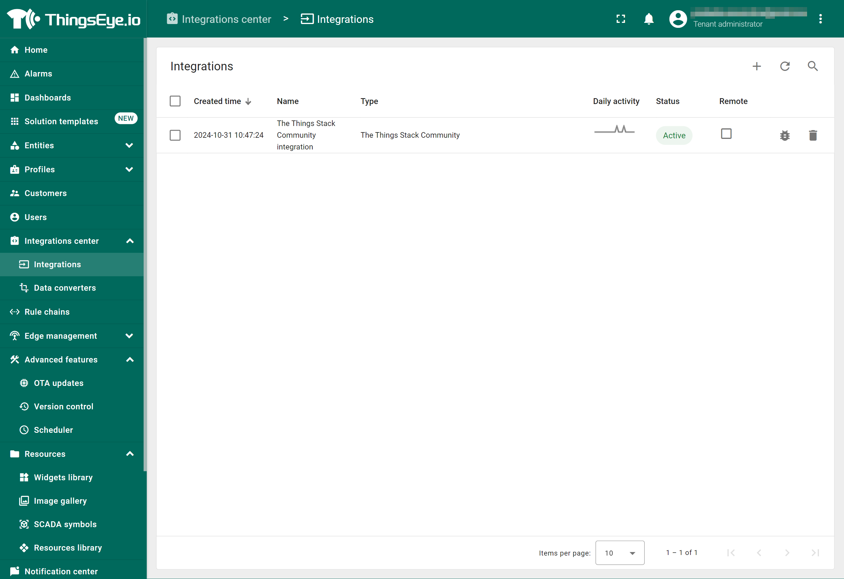
Your integration has been added to the Integrations list and will be displayed on the Integrations page. Check whether the status is shown as Active. If not, review your configuration settings and correct any errors.
2.9.1.3 Viewing integration details
Click on your integration from the list. The Integration details window will appear with the Details tab selected. The Details tab shows all the settings you have provided for this integration.
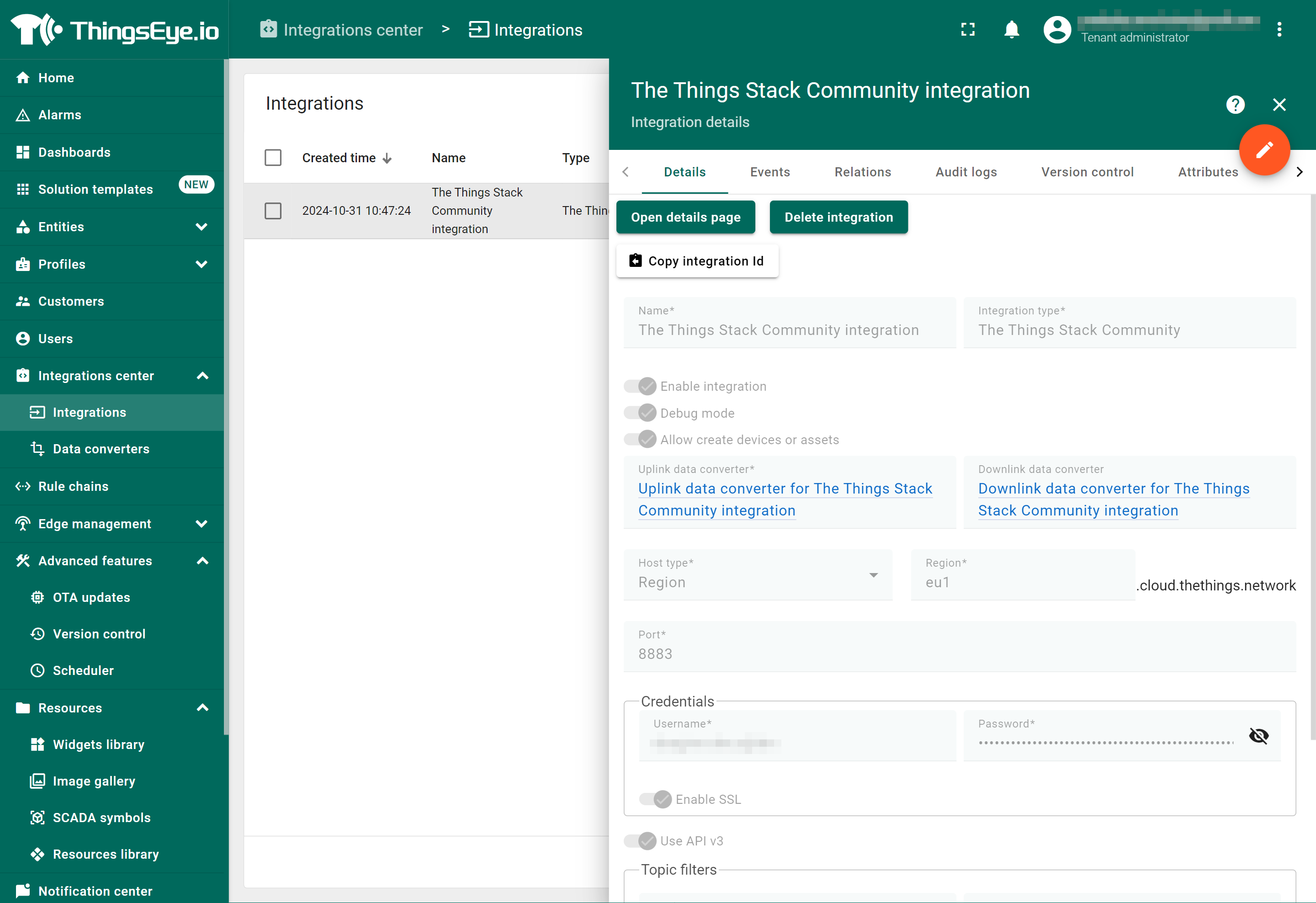
If you want to edit the settings you have provided, click on the Toggle edit mode button. Once you have done click on the Apply changes button.
See also ThingsEye documentation.
2.9.1.4 Viewing events
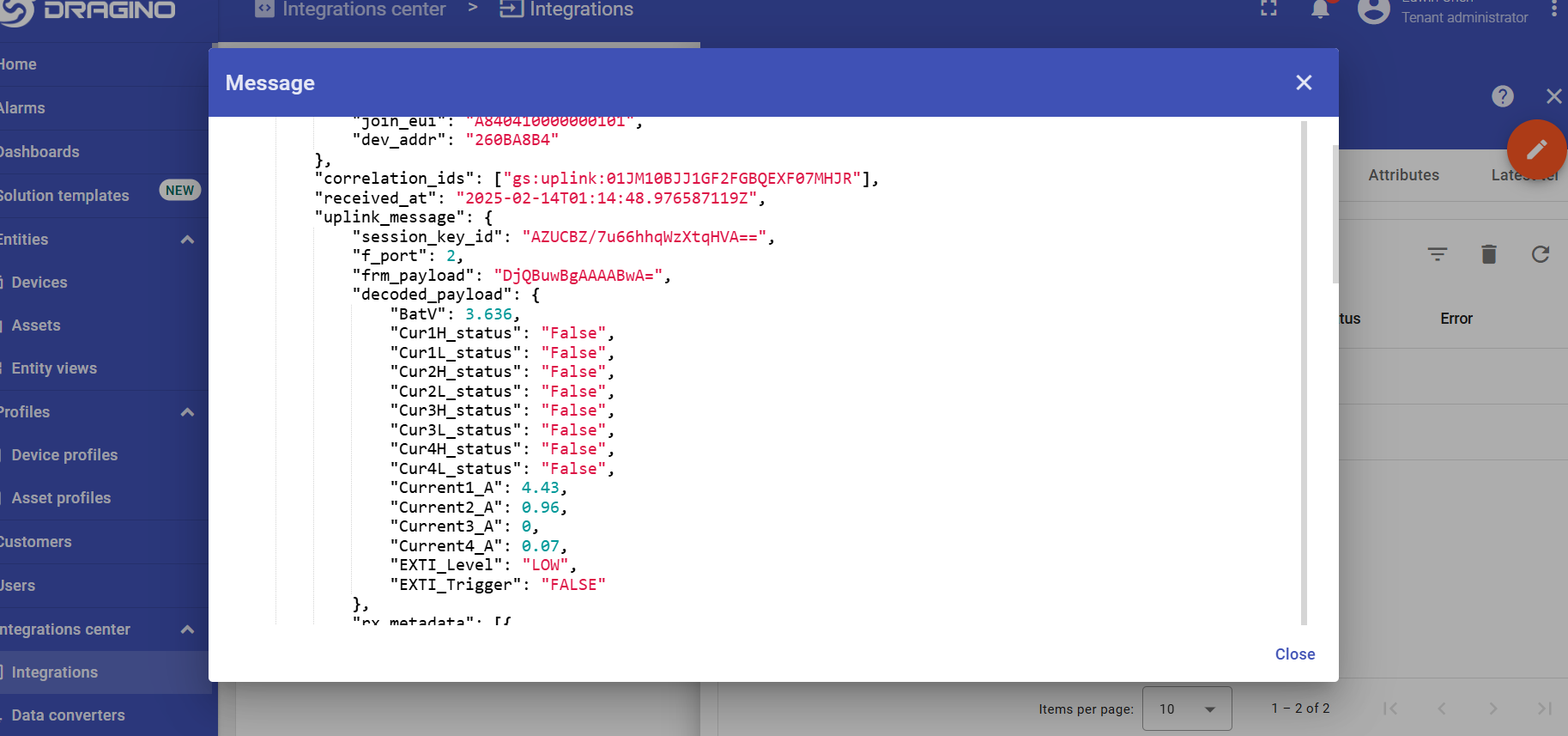
The Events tab displays all the uplink messages from the CS01-LB.
- Select Debug from the Event type dropdown.
- Select the time frame from the time window.
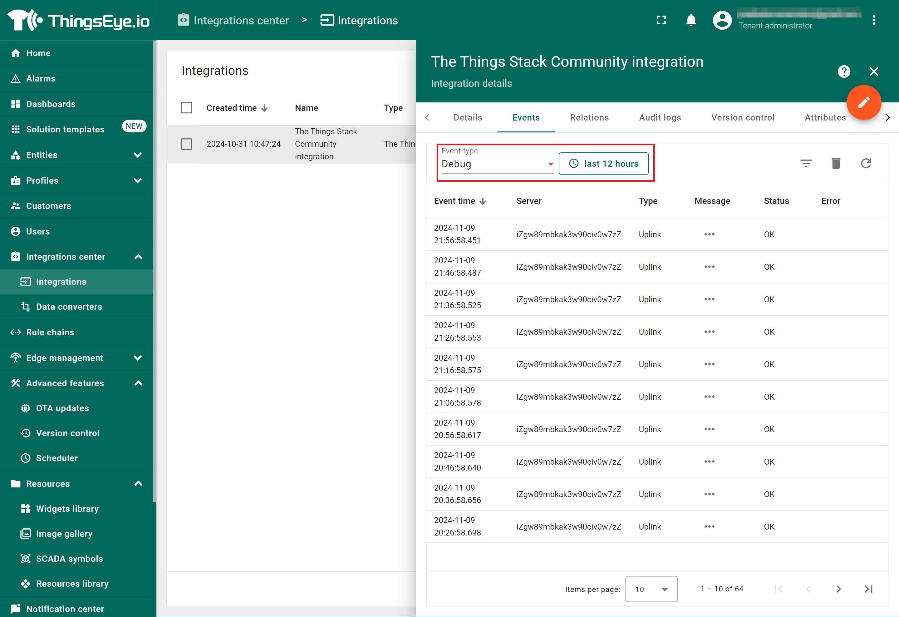
- To view the JSON payload of a message, click on the three dots (...) in the Message column of the desired message.
2.9.1.5 Deleting an integration
If you want to delete an integration, click the Delete integration button on the Integrations page.
2.9.1.6 Viewing sensor data on a dashboard
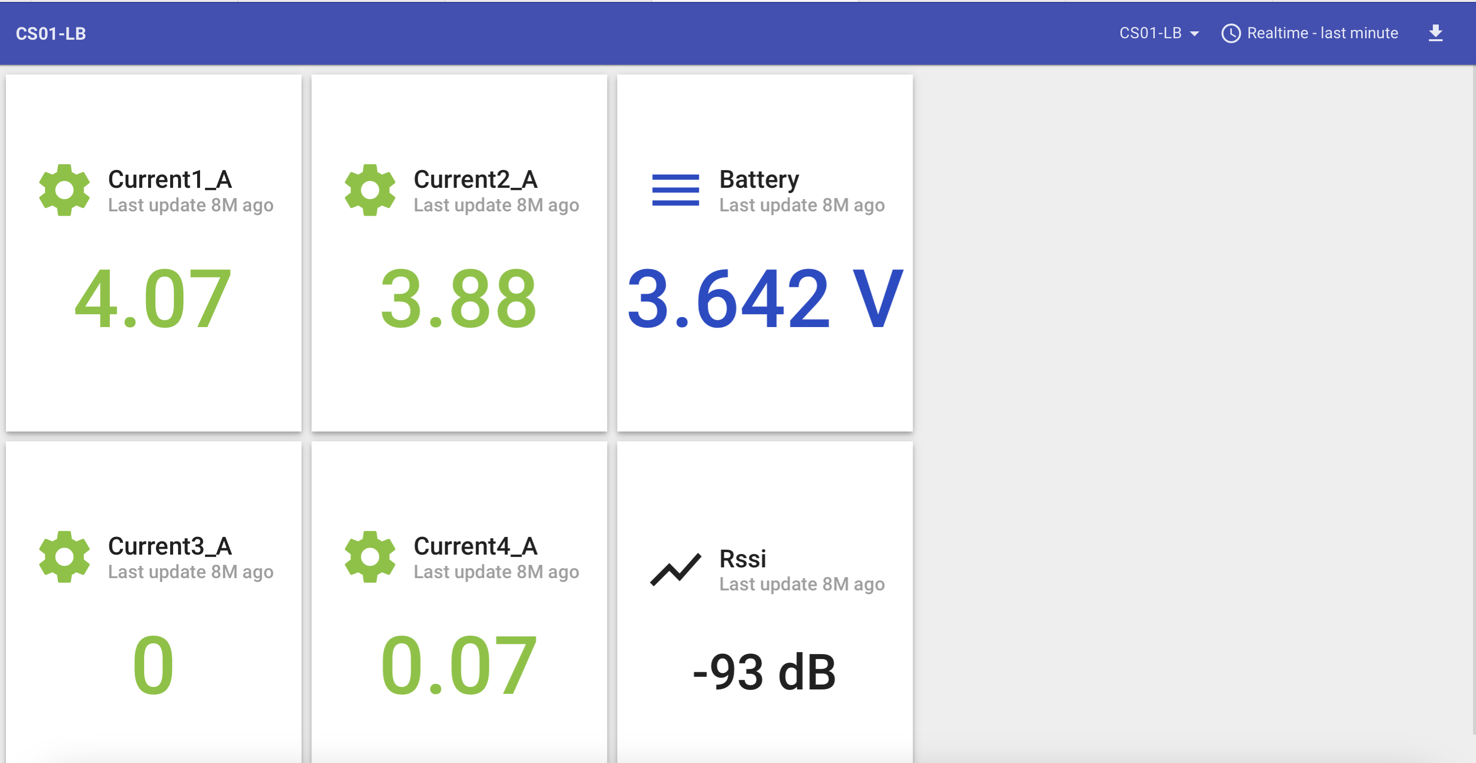
You can create a dashboard with ThingsEye to visualize the sensor data coming from the CS01-LB. The following image shows a dashboard created for the CS01-LB. See Creating a dashboard in ThingsEye documentation for more information.
3. Configure CS01-LB
3.1 Configure Methods
CS01-LB supports the following configuration methods:
- AT Command via Bluetooth Connection (Recommended): See BLE Configure Instructions.
- AT Command via UART Connection: See UART Connection.
- LoRaWAN Downlink: Instructions for different platforms can be found in the IoT LoRaWAN Serve section.
3.2 General Commands
These commands are used to configure:
- General system settings, such as the uplink interval.
- LoRaWAN protocol and radio-related commands.
They are the same for all Dragino devices that support the DLWS-005 LoRaWAN stack. These commands can be found on the wiki:
http://wiki.dragino.com/xwiki/bin/view/Main/End%20Device%20AT%20Commands%20and%20Downlink%20Command/
3.3 Commands Specially Designed for CS01-LB
These commands are only valid for CS01-LB, as listed below:
3.3.1 Set Uplink Transmit Interval
Feature: Change CS01-LB Uplink Transmit Interval.
AT Command: AT+TDC
| Command Example | Function | Response |
|---|---|---|
| AT+TDC=? | Get current uplink transmit interval | 30000 |
| AT+TDC=60000 | Set uplink transmit interval | OK |
Downlink Command: 0x01
Format: Command Code (0x01) followed by 3 bytes time value.
If the downlink payload=0100003C, it means set the END CS01-LB's transmit Interval to 0x00003C=60(S), while type code is 01.
- Example 1: Downlink Payload: 0100001E // Set Transmit Interval (TDC) = 30 seconds
- Example 2: Downlink Payload: 0100003C // Set Transmit Interval (TDC) = 60 seconds
3.3.2 Get Device Status
Send a LoRaWAN downlink to get the device status.
Downlink Payload: 0x26 01
Sensor will upload device status via FPort=5. See payload section for details.
3.3.3 Get Data
Feature: Get the current sensor data.
AT Command:
- AT+GETSENSORVALUE=0 // The serial port gets the reading of the current sensor
- AT+GETSENSORVALUE=1 // The serial port gets the current sensor reading and uploads it.
3.3.4 Set Interrupt Mode
Feature: Set Interrupt mode for GPIO_EXTI of pin.
When AT+INTMOD=0 is set, GPIO_EXTI is used as a digital input port.
AT Command: AT+INTMOD
| Command Example | Function | Response |
|---|---|---|
| AT+INTMOD=? | Show the current interrupt mode | 0 |
| AT+INTMOD=2 | Set interrupt mode: | OK |
Downlink Command: 0x06
Format: Command Code (0x06) followed by 3 bytes.
This means that the interrupt mode of the end node is set to 0x000003=3 (rising edge trigger), and the type code is 06.
- Example 1: Downlink Payload: 06000000 // Turn off interrupt mode
- Example 2: Downlink Payload: 06000003 // Set the interrupt mode to rising edge trigger
3.3.5 Set Power Output Duration
Control the output duration of 3.3V. Before each sampling, the device will:
- First, enable the power output to the external sensor.
- Keep it on for the specified duration, read the sensor value, and construct the uplink payload.
- Finally, turn off the power output.
AT Command: AT+3V3T
| Command Example | Function | Response |
|---|---|---|
| AT+3V3T=? | Show 3.3V open time. | 0 (default) OK |
| AT+3V3T=1000 | Close after a delay of 1000 milliseconds. | OK |
Downlink Command: 0x07
Format: Command Code (0x07) followed by 3 bytes.
The first byte indicates the voltage, the second and third bytes indicate the power output duration for the sensor.
- Example 1: Downlink Payload: 07 01 01 F4 ---> AT+3V3T=500
- Example 2: Downlink Payload: 07 01 FF FF ---> AT+3V3T=65535
3.3.6 Set Working Mode
Feature: Get or Set the working mode.
AT Command: AT+MOD
| Command Example | Function | Response |
|---|---|---|
| AT+MOD=? | Get the current Working Mode | 1 (default) OK |
| AT+MOD=2,60,5,0 | Set Working Mode 2 | OK |
Description of the AT instruction for setting Working Mode 2:
| Command Example | Function | Parameter |
|---|---|---|
| AT+MOD=1 | Set General acquisition mode. | 1: General acquisition mode. |
| AT+MOD=2,60,5 | The first parameter sets the continuous detection mode 2. | 2: Continuous acquisition mode. |
| The second parameter sets the detection sampling interval. | 60: Data were collected every 60 seconds. | |
| The third bit parameter sets the number of groups to record data. | After 5 groups of data are collected, the uplink is performed. | |
AT+MOD=2,60,5,0 | The first parameter sets the continuous detection mode 2. | 2: Continuous acquisition mode. |
| The second parameter sets the detection sampling interval. | 60: Data were collected every 60 seconds. | |
| The third bit parameter sets the number of groups to record data. | After 5 groups of data are collected, the uplink is performed. | |
The fourth parameter (This parameter is valid only for CS01-LS.) setting 5V normally open. Keep 5V on, standby current 16mA. | 0: Not set 5V normally open 1: Setting 5V normally open |
Downlink Command: 0x0A
Format: Command Code (0x0A) followed by 1 byte or 4bytes,5 bytes.
- Example 1: Downlink Payload: 0A 01 ---> AT+MOD=1
- Example 2: Downlink Payload: 0A 02 00 3C 05 ---> AT+MOD=2,60,5
- Example 3: Downlink Payload: 0A 02 00 3C 05 00 ---> AT+MOD=2,60,5,0
3.3.7 Set the Alarm Threshold
Feature: Get or set the current alarm threshold. (Takes effect only when AT+MOD=1)
Note: The third, fifth, seventh and ninth parameter units of the v1.0 version are A, and the units of the third, fifth, seventh, and ninth parameters of versions after v1.1 are mA.
AT Command: AT+CALARM
| Command Example | Function | Response |
|---|---|---|
AT+CALARM=? | Get current alarm threshold. | 0,0,0,0,0,0,0,0,0(default) |
AT+CALARM=1,1,20,1,20,0,0,0,0 | When the current of channel 1 and channel 2 exceeds 20A, it will alarm and send a data packet. | OK |
| Command Example | Function | Parameter |
|---|---|---|
AT+CALARM=1,1,10000,0,20000,0,0,0,0 | The first parameter enables or disables the threshold alarm. | 0: Not Alarm 1: Alarm |
| The second and third parameters set "current 1" below threshold alarm or above threshold alarm. | 0,xx: Means if value <xx, Then Alarm eg:1,10000: if value >10000mA(10A), Then Alarm | |
| The fourth and fifth parameters set "current 2" below the threshold alarm or above the threshold alarm. | 0,xx: Means if value <xx, Then Alarm eg:0,20000: if value <20000mA(20A), Then Alarm | |
| The sixth and seventh parameters set "current 3" below the threshold alarm or above the threshold alarm. | 0,0: Means if value <xx, Then Alarm eg:0,0: Disable this channel alarm | |
| The eighth and ninth parameters set "current 4" below the threshold alarm or above the threshold alarm. | 0,0: Means if value <xx, Then Alarm eg:0,0: Disable this channel alarm |
Downlink Command: 0x0B
Format: Command Code (0x0B) followed by 17 bytes.
- Example 1: Downlink Payload: 0B 01 01 00 27 10 00 00 4E 20 00 00 00 00 00 00 00 00 ---> AT+CALARM=1,1,10000,0,20000,0,0,0,0 => 1(01),1(01),10000(00 27 10),0(00),20000(00 4E 20),0(00),0(00 00 00),0(00),0(00 00 00)
- Example 2: Downlink Payload: 0B 01 00 00 00 00 00 00 00 00 00 00 03 E8 01 00 07 D0 ---> AT+CALARM=1,0,0,0,0,0,1000,1,2000 => 1(01),0(00),0(00 00 00),0(00),0(00 00 00),0(00),1000(00 03 E8),1(01),2000(00 07 D0)
- Example 3: Downlink Payload: 0B 00 00 00 00 00 00 00 00 00 00 00 00 00 00 00 00 00 ---> AT+CALARM=0,0,0,0,0,0,0,0,0 => 0(00),0(00),0(00 00 00),0(00),0(00 00 00),0(00),0(00 00 00),0(00),0(00 00 00)
Format: The first byte(Command Code ) is 0x0B, the last byte is 0x01 or 0x02, and the middle 9 bytes.
When the last byte is 0x01, you can set the first, second, third, fourth and fifth parameters of the AT command.
- Example 1: Downlink Payload: 0B 01 01 00 27 10 00 00 4E 20 01---> AT+CALARM=1,1,10000,0,20000,0,0,0,0 => 1(01),1(01),10000(00 27 10),0(00),20000(00 4E 20)
When the last byte is 0x02, you can set the first, sixth, seventh, eighth and ninth parameters of the AT command.
- Example 2: Downlink Payload: 0B 01 00 00 03 E8 01 00 07 D0 02---> AT+CALARM=1,0,0,0,0,0,1000,1,2000 => 1(01),0(00),1000(00 03 E8),1(01),2000(00 07 D0)
Format: Command Code (0x0B) followed by 9 bytes.
- Example 1: Downlink Payload: 0B 01 01 14 01 14 00 00 00 00 ---> AT+CALARM=1,1,20,1,20,0,0,0,0 (v1.0 version) =>1(01),1(01),20(14),1(01),20(14),0(00),0(00),0(00),0(00)
- Example 2: Downlink Payload: 0B 01 01 14 01 14 00 00 00 00 ---> AT+CALARM=1,1,20000,1,20000,0,0,0,0 (Versions after v1.1) =>1(01),1(01),20(14),1(01),20(14),0(00),0(00),0(00),0(00)
- Example 3: Downlink Payload: 0B 00 00 00 00 00 00 00 00 00 ---> AT+CALARM=0,0,0,0,0,0,0,0,0 =>0(00),0(00),0(00),0(00),0(00),0(00),0(00),0(00),0(00)
3.3.8 Set Alarm Interval
The shortest time of two Alarm packet(unit: min). The default is 20 minutes.
- AT Command:
AT+ATDC=30 // The shortest interval of two Alarm packets is 30 minutes, Means is there is an alarm packet uplink, there won't be another one in the next 30 minutes.
- Downlink Payload:
0x(0C 1E) ---> Set AT+ATDC=0x 1E = 30 minutes
3.3.9 Set enable or disable of the measurement channel
This command can be used when user connects less than four current sensors. This command can turn off unused measurement channels to save battery life.
AT Command: AT+ENCHANNEL
| Command Example | Function | Response |
|---|---|---|
| AT+ENCHANNEL=? | Get enabled channels. | 1,1,1,1 (Default) OK |
| AT+ENCHANNEL=1,1,1,0 | Channel 4 disabled. | OK |
| AT+ENCHANNEL=1,1,0,0 | Channel 3 and 4 disabled. | OK |
Downlink Command: 0x08
Format: Command Code (0x08) followed by 4 bytes.
The first byte means the first channel, the second byte means the second channel, the third byte means the third channel, and the fourth byte means the fourth channel.And 1 means enable channel, 0 means disable channel.
- Example 1: Downlink Payload: 08 01 01 01 01 ---> AT+ENCHANNEL=1,1,1,1 // All channels are enabled
- Example 2: Downlink Payload: 08 01 01 01 00 ---> AT+ENCHANNEL=1,1,1,0 // Channel 4 disabled
- Example 3: Downlink Payload: 08 01 01 00 00 ---> AT+ENCHANNEL=1,1,0,0 // Channel 3 and 4 disabled
3.3.10 Set the current proportion parameter (Since V1.2)
This command sets the processing multiplier of the actual value to get the displayed value.
The default current ratio parameter is 100, meaning the displayed value equals the actual value multiplied by 1, which is suitable for a standard 100A current transformer.
The valid range is 0 to 65535 (cannot be set to 0). If this value is set to 1000, the displayed value will be 10 times the actual value.
AT Command: AT+PROPORTION
| Command Example | Function | Response |
|---|---|---|
AT+PROPORTION=? | Get the current proportion parameter | 100 (Default) |
| AT+PROPORTION=1 | Set the displayed value to 1/100 of the actual value | OK |
| AT+PROPORTION=300 | Setting the display value to 3 times the actual value | OK |
Downlink Command: 0x0D
Format: Command Code (0x0D) followed by 2 bytes.
- Example 1: Downlink Payload: 0D 00 64 ---> AT+PROPORTION=100 // Set the displayed value to the actual value multiplied by 1, which is suitable for standard 100A current transformers.
- Example 2: Downlink Payload: 0D 01 2C ---> AT+PROPORTION=300 // Set the displayed value to the actual value multiplied by 3,which is suitable for standard 300A current transformers.
- Example 3: Downlink Payload: 0D 02 58 ---> AT+PROPORTION=600 // Set the displayed value to the actual value multiplied by 6,which is suitable for standard 600A current transformers.
Note: When using this command to set the current ratio parameter, it will simultaneously apply to all four channels. For example, setting AT+PROPORTION=300 means all four channels will use 300A CTs. If you need to use CTs with different measurement ranges across the four channels, please refer to FAQ 7.2.
3.3.11 Set current resolution (Since V1.2)
AT Command: AT+RESOLUTION
| Command Example | Function | Response |
|---|---|---|
AT+RESOLUTION=? | Get the current resolution | 0 (Default) OK |
AT+RESOLUTION=0 | Set the resolution to 0.01A, two decimal places | OK |
AT+RESOLUTION=1 | Set the resolution to 0.001A, three decimal places | OK |
Downlink Command: 0x0E
Format: Command Code (0x0E) followed by 1 byte.
- Example 1: Downlink Payload: 0E 00 ---> AT+RESOLUTION=0
- Example 2: Downlink Payload: 0E 01 ---> AT+RESOLUTION=1
4. Use Cases
4.1 Monitor the power status of an office

This is a case study for the CS01-LB current sensor. It shows how to use the CS01-LB to monitor an office's power usage status.
Click here for more: Case 1: Monitor the power status of an office
4.2 Function Setting: Power Consumption Calculation Case
- Set the alarm: When the current reaches 0.1, send data.
- Set the alarm interval to 5 minutes.
- Set the regular data interval to approximately 6 hours. The power outage alarm takes priority.
- Switch off the connected device.
- Look for the alarm message, as the current will drop to a minimum.
- Repeat the device switch-off after 8 minutes (since the alarm interval is set to 5 minutes) and check for the alarm message.
- In a scenario with 4 outages per day, we should receive 4 alarm messages and 4 regular current messages (with a data frequency set to 6 hours).
Question: How long will the battery last under these conditions?
The third, fifth, seventh, and ninth parameter units of version v1.0 are in A (Ampere), while the units of the same parameters in versions after v1.1 are in mA (Milliampere).
Below are my settings:
- AT+CALARM=1,0,0,0,0,0,0,0,100
- AT+ENCHANNEL=0,0,0,1

According to the settings, three aspects need to be calculated, as follows:
- Alarm Interval: The alarm occurs once every five minutes, 12 times per hour, for a total of 288 times per day. Each alarm is equivalent to one detection, and the consumption per detection is approximately 0.0172mAh. Therefore, the daily consumption is calculated as follows:
0.0172 * 288 = 4.9536mAh
- Sleep Current Consumption: The sleep current consumption per day is approximately 0.0053268 * 24 = 0.1278432mAh.
- Uplink Messages: There are 4 alarms + 4 regular current messages, which is equivalent to sending 8 uplink messages per day. Each upload consumes:
- Single sensor: 0.076761064mAh
- Four sensors: 0.109365489mAh
- So:
- Single sensor consumption per day: 0.076761064 * 8 = 0.614088512mAh
- Four sensors consumption per day: 0.109365489 * 8 = 0.874923912mAh
The CS01-LB battery capacity is 8500mAh. Based on the above data, the battery life is calculated as follows:
- Single sensor: 8500 / (4.9536 + 0.1278432 + 0.614088512) = 1492 days
- Four sensors: 8500 / (4.9536 + 0.1278432 + 0.874923912) = 1427 days
This is an approximate calculation of battery life. The actual battery life also depends on the frequency band and DR (Data Rate) you use. See the figure below for details
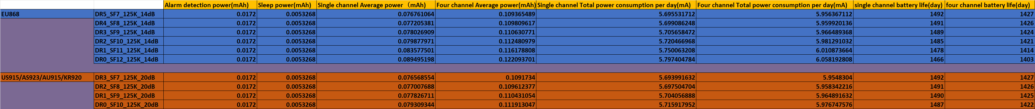
5. Battery & Power Consumption
The CS01-LB uses an ER26500 + SPC1520 battery pack. See the link below for detailed information about the battery and how to replace it:
Battery Info & Power Consumption Analysis.
Note: Continuous sampling mode will significantly increase power consumption.
For example, if all four channels are used for sampling data:
- Sample every minute and uplink data every 5 minutes: The battery life is about 10 months.
- Sample every minute and uplink data every 20 minutes: The battery life is about 12 months.
If you want to use an external DC adapter to power the CS01-LB in this case, please refer to Power Device using a 3.3v Power Adapter.
6. OTA Firmware update
User can update the CS01-LB firmware to:
- Change the frequency band/region.
- Update with new features.
- Fix bugs.
Firmware and changelog can be downloaded from : Firmware download link
Methods to Update Firmware:
- Recommended method: OTA firmware update via wireless : http://wiki.dragino.com/xwiki/bin/view/Main/Firmware%20OTA%20Update%20for%20Sensors/
- Update through the UART TTL interface : Instruction.
7. FAQ
7.1 Why can't current clamps measure current over range?
First, we take the SCT036-600 as an example to explain the specifications of the current clamp.
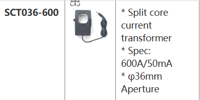
Meaning of *Spec: 600A/50mA :
- 600A: indicates that the maximum range of the current clamp is 600 amps, that is, the maximum current value that can be measured.
- 50mA: Indicates that the resolution of the current clamp is 50mA, which is the smallest current change that can be detected.
Why can't you measure current over range:
Reduced accuracy: Exceeding the range will lead to increased measurement errors and inaccurate results.
Equipment damage: Excessive current may damage the sensor or circuit inside the current clamp.
Safety risks: Over-range measurement may cause overheating, short circuit and other problems, resulting in safety risks.
7.2 How to modify Payload to match 100A/300A/600A sensors respectively?
When using 300A or 600A current transformers, discrepancies may occur between the measured current values and actual readings due to parameter ratio inconsistencies
Users need to amplify the current readings in equal proportions:
When users use 300A transformers, they need to amplify the current readings by 3 times.
When users use 600A transformers, they need to amplify the current readings by 6 times.
There are two ways:
1. You can use the AT+PROPORTION command to simultaneously control the amplification of 4 channels to the same multiple. For specific usage, please refer to: AT+PROPORTION
2. If the 4 channels use sensors with different ranges, you need to change the output ratio in decoding. The operation is as follows:

The final current output is multiplied by the ratio. For example:
When the mutual inductor used by channel 1 and channel 2 is 300A, modify it as follows:
- decode.Current1_A=((bytes[2]<<8 | bytes[3])/100)*3;
- decode.Current2_A=((bytes[4]<<8 | bytes[5])/100)*3;
When the transformer used by channel 3 and channel 4 is 600A, modify as follows:
- decode.Current3_A=((bytes[6]<<8 | bytes[7])/100)*6;
- decode.Current4_A=((bytes[8]<<8 | bytes[9])/100)*6;
8. Troubleshooting
8.1 Why are the collected current values inaccurate?
When the current value collected by the node is inaccurate, please check whether the calibration value is set using the AT+CCAL command in the node. If so, change the calibration value to 0, as follows:
AT+CCAL=0,0,0,0.
Configure Methods:
9. Ordering Information
Part Number: CS01-LB-XX
XX: The default frequency band
- AS923: LoRaWAN AS923 band
- AU915: LoRaWAN AU915 band
- EU433: LoRaWAN EU433 band
- EU868: LoRaWAN EU868 band
- KR920: LoRaWAN KR920 band
- US915: LoRaWAN US915 band
- IN865: LoRaWAN IN865 band
- CN470: LoRaWAN CN470 band
Note: CS01-LB doesn't include a current sensor. You need to purchase it separately.
Reference Models for current sensors:
- SCT013G-D-100: 100A/50mA
- SCT024-300: 300A/50mA
- SCT036-600: 600A/50mA
10. Packaging Information
Package Includes:
- CS01-LB LoRaWAN 4 Channels Current Sensor Converter
Dimension and weight:
Package Size / pcs :
- For CS01-LB: 145*105*55 mm
- For CS01-LS: mm
Weight / pcs :
- For CS01-LB: 310 g
- For CS01-LS: g
Transformer size and weight:
Package Size / pcs :
- For SCT013G-D-100: 100*80*30 mm
- For SCT024-300: 69*50*107 mm
- For SCT036-600: 74*74*100 mm
Weight / pcs :
- For SCT013G-D-100: 80g
- For SCT024-300: 209 g
- For SCT036-600: 330 g
11. Support
- Support is available Monday to Friday, from 09:00 to 18:00 GMT+8. Due to different time zones, we cannot offer live support. However, your questions will be answered as soon as possible within the aforementioned schedule.
- Please provide as much information as possible regarding your inquiry, including product models, a detailed description of the problem, and steps to replicate it. Send your email to support@dragino.cc