CS01-LB -- LoRaWAN 4 Channels Current Sensor Converter User Manual
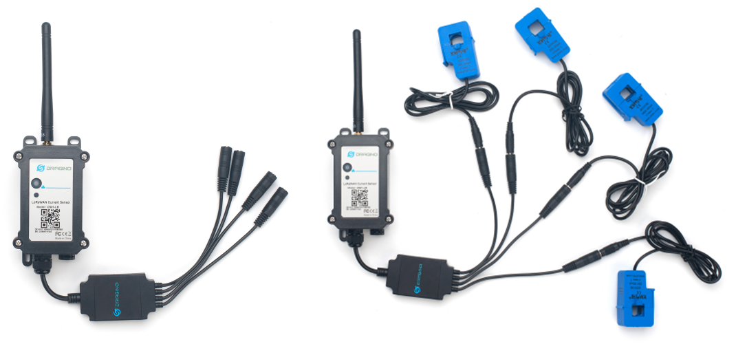
Table of Contents:
- 1. Introduction
- 2. Configure CS01-LB to connect to LoRaWAN network
- 2.1 How it works
- 2.2 Quick guide to connect to LoRaWAN server (OTAA)
- 2.3 Device Status, FPORT=5
- 2.4 Working Mode & Uplink Payload
- 2.5 Payload Decoder file
- 2.6 Datalog Feature
- 2.7 Frequency Plans
- 2.8 Firmware Change Log
- 3. Configure CS01-LB
- 4. Use Case
- 5. Battery & Power Consumption
- 6. OTA Firmware update
- 7. FAQ
- 8. Order Info
- 9. Packing Info
- 10. Support
1. Introduction
1.1 What is LoRaWAN 4 Channels Current Sensor Converter
The Dragino CS01-LB is a LoRaWAN 4 Channels Current Sensor Converter. It can convert the reading from current sensors and upload to IoT server via LoRaWAN Network.
CS01-LB can be used to monitor the machine running status and analyze power consumption trends.
The CS01-LB supports maximum 4 current sensors. The current sensors are detachable and can be replaced with different scales.
CS01-LB supports BLE configure and wireless OTA update which make user easy to use.
CS01-LB is powered by 8500mAh Li-SOCI2 battery, it is designed for long-term use up to several years.
Each CS01-LB is pre-load with a set of unique keys for LoRaWAN registrations, register these keys to local LoRaWAN server and it will auto-connect after power on.
1.2 Features
- LoRaWAN 1.0.3 Class A
- Bands:CN470/EU433/KR920/US915/EU868/AS923/AU915/IN865
- Ultra-low power consumption
- Supports maximum 4 current sensors
- Support various current sensor Ratio: 50A, 100A etc.
- Monitor the machine running status
- Analyze power consumption trends
- Current Alarm
- Support Bluetooth v5.1 and LoRaWAN remote configure
- Support wireless OTA update firmware
- Uplink on periodically
- Downlink to change configure
- 8500mAh Li/SOCl2 Battery
1.3 Specification
Common DC Characteristics:
- Supply Voltage: Built-in Battery , 2.5v ~ 3.6v
- Operating Temperature: -40 ~ 85°C
LoRa Spec:
- Frequency Range, Band 1 (HF): 862 ~ 1020 Mhz
- Max +22 dBm constant RF output vs.
- RX sensitivity: down to -139 dBm.
- Excellent blocking immunity
Battery:
- Li/SOCI2 un-chargeable battery
- Capacity: 8500mAh
- Self-Discharge: <1% / Year @ 25°C
- Max continuously current: 130mA
- Max boost current: 2A, 1 second
Power Consumption
- Sleep Mode: 5uA @ 3.3v
- LoRa Transmit Mode: 125mA @ 20dBm, 82mA @ 14dBm
1.4 Sleep mode and working mode
Deep Sleep Mode: Sensor doesn't have any LoRaWAN activate. This mode is used for storage and shipping to save battery life.
Working Mode: In this mode, Sensor will work as LoRaWAN Sensor to Join LoRaWAN network and send out sensor data to server. Between each sampling/tx/rx periodically, sensor will be in IDLE mode, in IDLE mode, sensor has the same power consumption as Deep Sleep mode.
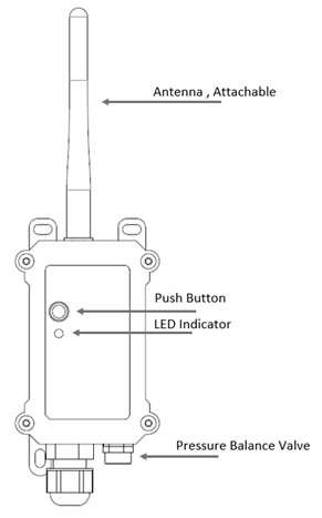
1.5 Button & LEDs
| Behavior on ACT | Function | Action |
|---|---|---|
| Pressing ACT between 1s < time < 3s | Send an uplink | If sensor is already Joined to LoRaWAN network, sensor will send an uplink packet, blue led will blink once. |
| Pressing ACT for more than 3s | Active Device | Green led will fast blink 5 times, device will enter OTA mode for 3 seconds. And then start to JOIN LoRaWAN network. |
| Fast press ACT 5 times. | Deactivate Device | Red led will solid on for 5 seconds. Means device is in Deep Sleep Mode. |
1.6 BLE connection
CS01-LB supports BLE remote configure.
BLE can be used to configure the parameter of sensor or see the console output from sensor. BLE will be only activate on below case:
- Press button to send an uplink
- Press button to active device.
- Device Power on or reset.
If there is no activity connection on BLE in 60 seconds, sensor will shut down BLE module to enter low power mode.
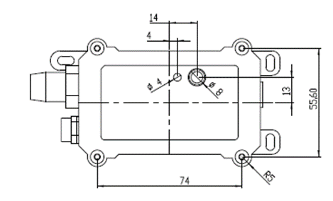
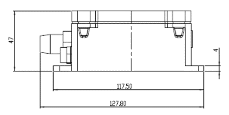
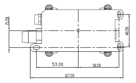
1.7 Mechanical
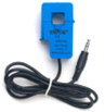
1.8 Current Sensor Spec
The current sensor list below is not ship with CS01-LB, user need to order seperately:
| Model | Photo | Specification |
|---|---|---|
| SCT013G-D-100 |
| * Split core current transformer * Spec: 100A/50mA * φ16mm Aperture * Material of core: Ferrite |
2. Configure CS01-LB to connect to LoRaWAN network
2.1 How it works
The CS01-LB is configured as LoRaWAN OTAA Class A mode by default. It has OTAA keys to join LoRaWAN network. To connect a local LoRaWAN network, you need to input the OTAA keys in the LoRaWAN IoT server and press the button to activate the CS01-LB. It will automatically join the network via OTAA and start to send the sensor value. The default uplink interval is 20 minutes.
Notice: CS01-LB doesn't include current sensor. User needs to get the current sensor separately and attach to CS01-LB for measuring.
2.2 Quick guide to connect to LoRaWAN server (OTAA)
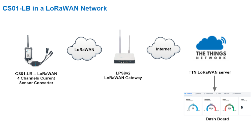
Following is an example for how to join the TTN v3 LoRaWAN Network. Below is the network structure; we use the LPS8v2 as a LoRaWAN gateway in this example.
The LPS8V2 is already set to connected to TTN network , so what we need to now is configure the TTN server.
Step 1: Create a device in TTN with the OTAA keys from CS01-LB.
Each CS01-LB is shipped with a sticker with the default device EUI as below:
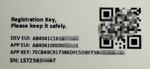
You can enter this key in the LoRaWAN Server portal. Below is TTN screen shot:
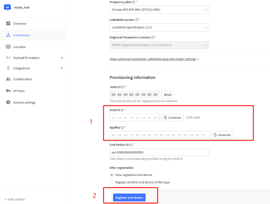
Register the device
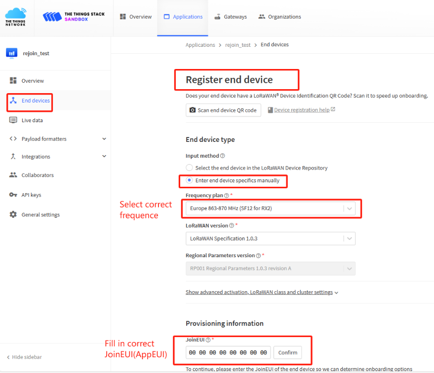
Add DevEUI and AppKey
Step 2: Activate on CS01-LB
Press the button for 5 seconds to activate the CS01-LB.
Green led will fast blink 5 times, device will enter OTA mode for 3 seconds. And then start to JOIN LoRaWAN network. Green led will solidly turn on for 5 seconds after joined in network.
After join success, it will start to upload messages to TTN and you can see the messages in the panel.
2.3 Device Status, FPORT=5
Users can use the downlink command(0x26 01) to ask CS01-LB to send device configure detail, include device configure status. CS01-LB will uplink a payload via FPort=5 to server.
The Payload format is as below.
| Device Status (FPORT=5) | |||||
| Size (bytes) | 1 | 2 | 1 | 1 | 2 |
| Value | Sensor Model | Firmware Version | Frequency Band | Sub-band | BAT |
Example parse in TTNv3.
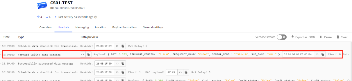
Sensor Model: For CS01-LB, this value is 0x33
Firmware Version: 0x0100, Means: v1.0.0 version
Frequency Band:
- 0x01: EU868
- 0x02: US915
- 0x03: IN865
- 0x04: AU915
- 0x05: KZ865
- 0x06: RU864
- 0x07: AS923
- 0x08: AS923-1
- 0x09: AS923-2
- 0x0a: AS923-3
- 0x0b: CN470
- 0x0c: EU433
- 0x0d: KR920
- 0x0e: MA869
Sub-Band:
AU915 and US915:value 0x00 ~ 0x08
CN470: value 0x0B ~ 0x0C
Other Bands: Always 0x00
Battery Info:
Check the battery voltage.
Ex1: 0x0B45 = 2885mV
Ex2: 0x0B49 = 2889mV
2.4 Working Mode & Uplink Payload
2.4.1 MOD=1(General acquisition mode), FPORT=2
MOD=1 is the default mode. End Node will uplink the real-time current sensor value in two case:
- Each TDC Interval.
- Trigger Alarm according to AT+CALARM configure.
Uplink packets use FPORT=2.
Size(bytes) | 2 | 2 | 2 | 2 | 2 | 1 |
|---|---|---|---|---|---|---|
| Value | Battery Info&Interrupt flag & Interrupt Level | Current channel 1 | Current channel 2 | Current channel 3 | Current channel 4 | Alarm_status* |
Alarm_status is a combination for Cur1L_status, Cur1H_status, Cur2L_status, Cur2H_status, Cur3L_status, Cur3H_status, Cur4L_status and Cur4H_status.
Totally 1bytes as below:
Bit7 | Bit6 | Bit5 | Bit4 | Bit3 | Bit2 | Bit1 | Bit0 |
|---|---|---|---|---|---|---|---|
Cur1L | Cur1H | Cur2L | Cur2H | Cur3L | Cur3H | Cur4L | Cur4H |
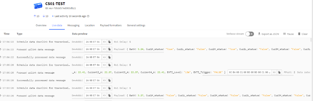
Example parse in TTNv3.
Battery Info
Check the battery voltage for LDS12-LB/LS.
Ex1: 0x0B45&0x3FFF = 2885mV
Ex2: 0x0B49&0x3FFF = 2889mV
Interrupt Flag & Interrupt Level
This data field shows if this packet is generated by interrupt or not. Click here for the hardware and software set up.
Note: The Interrupt Pin refers to the GPIO_EXTI pin in the screw terminal. See pin mapping.
Example:
If byte[0]&0x80>>15=0x00 : Normal uplink packet.
If byte[0]&0x80>>15=0x01 : Interrupt Uplink Packet.
If byte[0]&0x40>>14=0x00 : Interrupt pin low level.
If byte[0]&0x40>>14=0x01 : Interrupt pin high level.
Current channel 1:
Channel 1 for measuring AC current. Resolution 0.01A.
Ext: 0x03e8 =1000/100=10.00A
Current channel 2:
Channel 2 for measuring AC current. Resolution 0.01A.
Ext: 0x041A =1050/100=10.50A
Current channel 3:
Channel 3 for measuring AC current. Resolution 0.01A.
Ext: 0x044C =1100/100=11.00A
Current channel 4:
Channel 4 for measuring AC current. Resolution 0.01A.
Ext: 0x04B0 =1200/100=12.00A
Cur1L_status:
When setting the current threshold alarm of channel 1, this flag is True when it is lower than the set threshold, otherwise it is False.
Cur1H_status:
When setting the current threshold alarm of channel 1, this flag is True when it is higher than the set threshold, otherwise it is False.
Cur2L_status:
When setting the current threshold alarm of channel 2, this flag is True when it is lower than the set threshold, otherwise it is False.
Cur2H_status:
When setting the current threshold alarm of channel 2, this flag is True when it is higher than the set threshold, otherwise it is False.
Cur3L_status:
When setting the current threshold alarm of channel 3, this flag is True when it is lower than the set threshold, otherwise it is False.
Cur3H_status:
When setting the current threshold alarm of channel 3, this flag is True when it is higher than the set threshold, otherwise it is False.
Cur4L_status:
When setting the current threshold alarm of channel 4, this flag is True when it is lower than the set threshold, otherwise it is False.
Cur4H_status:
When setting the current threshold alarm of channel 4, this flag is True when it is higher than the set threshold, otherwise it is False.
2.4.2 MOD=2(Continuous Sampling Mode), FPORT=7
In Continuous Sampling Mode(AT+MOD=2,aa,bb), CS01 will record the current sensor data at a fix interval, and report multiply group of data together to IoT server later.
Notice: This mode has high power consumption. External power supply might be needed. More detail please check power consumption section.
AT+MOD=2,aa,bb format:
- First Parameter set to 2: Set CS01-LB to work in Continuous Sampling Mode.
- aa : Set Sampling Interval, Unit: Second.
- bb : Define how many group of data will be uplink together.
When CS01-LB is in Continuous Sampling Mode, the TDC time setting is disabled, and CS01-LB will send uplink once it finished the number of sampling define in "bb".
Example Command:AT+MOD=2,60,5
CS01-LB will read 4 channels data every 1 minutes. When it reads 5 groups, CS01-LB will send an uplink. So the uplink interval is 5 minutes. Each uplink will include 5 groups of sensor value. Each Group include 4 channels data. so the payload for each uplink will include:
- Battery (2 bytes)
- + Group1 Sensor Value (8 Bytes): the last 4th reading for Channel 1 + Channel 2 + Channel 3 + Channel 4
- + Group2 Sensor Value (8 Bytes): the last 3rd reading for Channel 1 + Channel 2 + Channel 3 + Channel 4
- + Group3 Sensor Value (8 Bytes): the last 2nd reading for Channel 1 + Channel 2 + Channel 3 + Channel 4
- + Group4 Sensor Value (8 Bytes): the last reading for Channel 1 + Channel 2 + Channel 3 + Channel 4
- + Group5 Sensor Value (8 Bytes): current reading for Channel 1 + Channel 2 + Channel 3 + Channel 4
So totally 42 bytes payload in this example.
Notice: Continuous Sampling Mode might generate a long payload, CS01-LB will choose the suitable DR to uplink the data. This might decrease the transmit distance.
Uplink packets use FPORT=7.
Size(bytes) | 2 | Dynamic Lenght , Depend on how many groups | |||||
|---|---|---|---|---|---|---|---|
Value | BAT | Sensor value, each 8 bytes is a set of sensor values(The maximum is 30 groups). | |||||
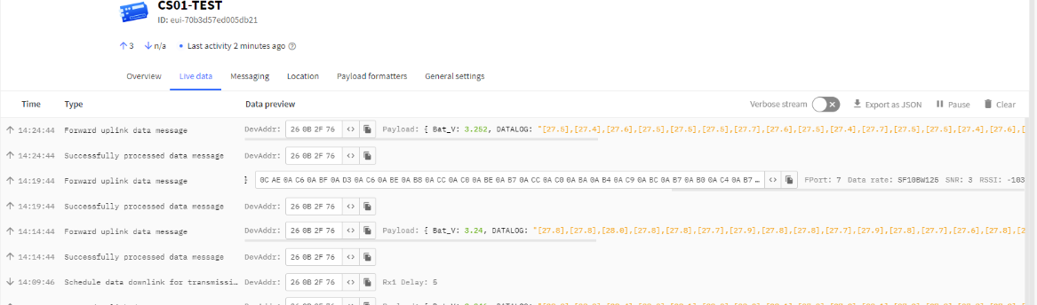
Example parse in TTNv3.
2.5 Payload Decoder file
In TTN, use can add a custom payload so it shows friendly reading
In the page Applications --> Payload Formats --> Custom --> decoder to add the decoder from:
https://github.com/dragino/dragino-end-node-decoder/tree/main/CS01-LB
2.6 Datalog Feature
Datalog Feature is to ensure IoT Server can get all sampling data from Sensor even if the LoRaWAN network is down. For each sampling, CS01-LB will store the reading for future retrieving purposes.
2.6.1 Ways to get datalog via LoRaWAN
Set PNACKMD=1, CS01-LB will wait for ACK for every uplink, when there is no LoRaWAN network, CS01-LB will mark these records with non-ack messages and store the sensor data, and it will send all messages (10s interval) after the network recovery.
a) CS01-LB will do an ACK check for data records sending to make sure every data arrive server.
b) CS01-LB will send data in CONFIRMED Mode when PNACKMD=1, but CS01-LB won't re-transmit the packet if it doesn't get ACK, it will just mark it as a NONE-ACK message. In a future uplink if CS01-LB gets a ACK, CS01-LB will consider there is a network connection and resend all NONE-ACK messages.
2.6.2 Unix TimeStamp
CS01-LB uses Unix TimeStamp format based on
User can get this time from link: https://www.epochconverter.com/ :
Below is the converter example
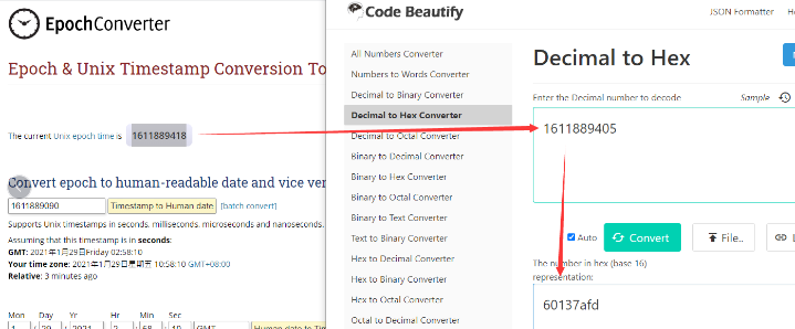
So, we can use AT+TIMESTAMP=1611889405 or downlink 3060137afd00 to set the current time 2021 – Jan -- 29 Friday 03:03:25
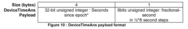
2.6.3 Set Device Time
User need to set SYNCMOD=1 to enable sync time via MAC command.
Once CS01-LB Joined LoRaWAN network, it will send the MAC command (DeviceTimeReq) and the server will reply with (DeviceTimeAns) to send the current time to CS01-LB. If CS01-LB fails to get the time from the server, CS01-LB will use the internal time and wait for next time request (AT+SYNCTDC to set the time request period, default is 10 days).
Note: LoRaWAN Server need to support LoRaWAN v1.0.3(MAC v1.0.3) or higher to support this MAC command feature, Chirpstack,TTN V3 v3 and loriot support but TTN V3 v2 doesn't support. If server doesn't support this command, it will through away uplink packet with this command, so user will lose the packet with time request for TTN V3 v2 if SYNCMOD=1.
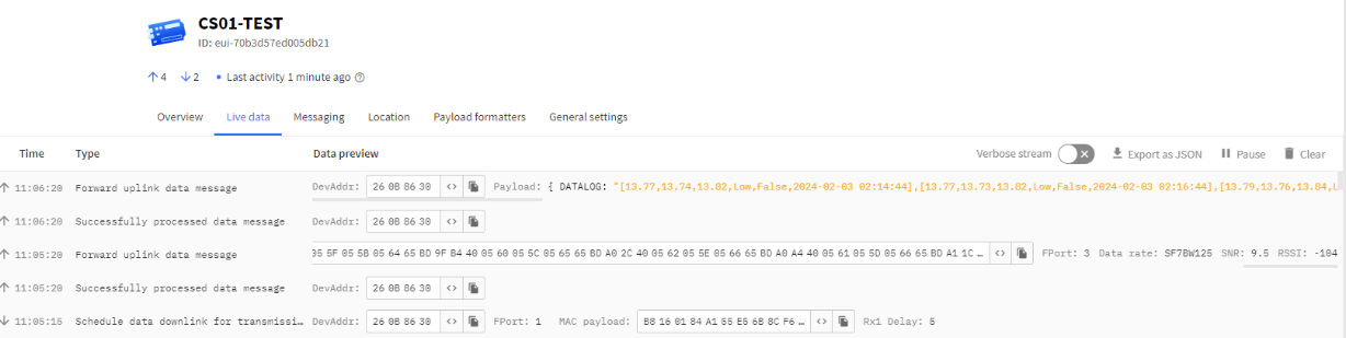
2.6.4 Datalog Uplink payload (FPORT=3)
The Datalog uplinks will use below payload format.
Retrieval data payload:
Size(bytes) | 1 | 2 | 2 | 2 | 4 |
|---|---|---|---|---|---|
| Value | Interrupt flag & Interrupt_level
| Current1 | Current2 | Current3 | Unix TimeStamp |
Interrupt flag & Interrupt level :
Size(bit) | bit7 | bit6 | [bit5:bit2] | bit1 | bit0 |
|---|---|---|---|---|---|
| Value | NO ACK message
| Poll Message Flag | Reserve | interrupt level | interrupt flag |
No ACK Message: 1: This message means this payload is fromn Uplink Message which doesn't get ACK from the server before ( for PNACKMD=1 feature)
Poll Message Flag: 1: This message is a poll message reply.
- Poll Message Flag is set to 1.
- Each data entry is 11 bytes, to save airtime and battery, devices will send max bytes according to the current DR and Frequency bands.
For example, in US915 band, the max payload for different DR is:
a) DR0: max is 11 bytes so one entry of data
b) DR1: max is 53 bytes so devices will upload 4 entries of data (total 44 bytes)
c) DR2: total payload includes 11 entries of data
d) DR3: total payload includes 22 entries of data.
If devise doesn't have any data in the polling time. Device will uplink 11 bytes of 0
Example:
If CS01-LB has below data inside Flash:
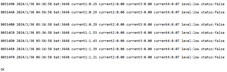
If user sends below downlink command: 3165BD971865BDA5283C
Where : Start time: 65BD9718 = time 23/5/24 03:30:41
Stop time: 65BDA528= time 23/5/24 03:33:00
CS01-LB will uplink this payload.
4005650562056A65BD974440055D0559056265BD97BC400562055E056765BD98344005640560056965BD98AC40056A0566056F65BD992440056A0566056F65BD999C4005680564056D65BD9A144005670563056C65BD9A8C4005680564056D65BD9B0440055F055E056765BD9B7C40055F055C056465BD9BF44005660562056B65BD9C6C400562055F056765BD9CE4400562055E056765BD9D5C40055C0558056165BD9DD4400560055C056565BD9E4C400561055D056665BD9EC44005650561056965BD9F3C40055F055B056465BD9FB4400560055C056565BDA02C400562055E056665BDA0A4400561055D056665BDA11C
Where the first 11 bytes is for the first entry:
40 05 65 05 62 05 6A 65 BD 97 44
Current1=0x0565/100=13.81
Current2=0x0562/100=13.78
Current3=0x056A/100=13.86
Interrupt flag & Interrupt_level=0x40, means reply data, sampling uplink message, interrupt level is low and interrupt flag is false.
Unix time is 0x65BD9744=1706923844s=24/2/3 01:30:44
2.7 Frequency Plans
The CS01-LB uses OTAA mode and below frequency plans by default. Each frequency band use different firmware, user update the firmware to the corresponding band for their country.
http://wiki.dragino.com/xwiki/bin/view/Main/End%20Device%20Frequency%20Band/
2.8 Firmware Change Log
Firmware download link: https://www.dropbox.com/scl/fo/cnnyz4ynebs3am96jvtv0/h?rlkey=4no594ssi0nzt2lc3irbkid9b&dl=0
3. Configure CS01-LB
3.1 Configure Methods
CS01-LB supports below configure method:
- AT Command via Bluetooth Connection (Recommended): BLE Configure Instruction.
- AT Command via UART Connection : See UART Connection.
- LoRaWAN Downlink. Instruction for different platforms: See IoT LoRaWAN Server section.
3.2 General Commands
These commands are to configure:
- General system settings like: uplink interval.
- LoRaWAN protocol & radio related command.
They are same for all Dragino Devices which support DLWS-005 LoRaWAN Stack. These commands can be found on the wiki:
http://wiki.dragino.com/xwiki/bin/view/Main/End%20Device%20AT%20Commands%20and%20Downlink%20Command/
3.3 Commands special design for CS01-LB
These commands only valid for CS01-LB, as below:
3.3.1 Set Transmit Interval Time
Feature: Change LoRaWAN End Node Transmit Interval.
AT Command: AT+TDC
| Command Example | Function | Response |
|---|---|---|
| AT+TDC=? | Show current transmit Interval | 30000 |
| AT+TDC=60000 | Set Transmit Interval | OK |
Downlink Command: 0x01
Format: Command Code (0x01) followed by 3 bytes time value.
If the downlink payload=0100003C, it means set the END Node's Transmit Interval to 0x00003C=60(S), while type code is 01.
- Example 1: Downlink Payload: 0100001E // Set Transmit Interval (TDC) = 30 seconds
- Example 2: Downlink Payload: 0100003C // Set Transmit Interval (TDC) = 60 seconds
3.3.2 Get Device Status
Send a LoRaWAN downlink to ask device send Alarm settings.
Downlink Payload: 0x26 01
Sensor will upload Device Status via FPORT=5. See payload section for detail.
3.3.3 Get data
Feature: Get the current sensor data.
AT Command:
- AT+GETSENSORVALUE=0 // The serial port gets the reading of the current sensor
- AT+GETSENSORVALUE=1 // The serial port gets the current sensor reading and uploads it.
3.3.4 Set Interrupt Mode
Feature, Set Interrupt mode for PA8 of pin.
When AT+INTMOD=0 is set, PA8 is used as a digital input port.
AT Command: AT+INTMOD
| Command Example | Function | Response |
|---|---|---|
| AT+INTMOD=? | Show current interrupt mode | 0 |
| AT+INTMOD=2 | Set Transmit Interval | OK |
Downlink Command: 0x06
Format: Command Code (0x06) followed by 3 bytes.
This means that the interrupt mode of the end node is set to 0x000003=3 (rising edge trigger), and the type code is 06.
- Example 1: Downlink Payload: 06000000 // Turn off interrupt mode
- Example 2: Downlink Payload: 06000003 // Set the interrupt mode to rising edge trigger
3.3.5 Set Power Output Duration
Control the output duration 3.3V. Before each sampling, device will
1. first enable the power output to external sensor,
2. keep it on as per duration, read sensor value and construct uplink payload
3. final, close the power output.
AT Command: AT+3V3T
| Command Example | Function | Response |
|---|---|---|
| AT+3V3T=? | Show 3.3V open time. | 0 (default) OK |
| AT+3V3T=1000 | Close after a delay of 1000 milliseconds. | OK |
Downlink Command: 0x07
Format: Command Code (0x07) followed by 3 bytes.
The first byte is which power, the second and third bytes are the time to turn on.
- Example 1: Downlink Payload: 07 01 01 F4 ---> AT+3V3T=500
- Example 2: Downlink Payload: 07 01 FF FF ---> AT+3V3T=65535
3.3.6 Set working mode
Feature, Get or Set working mode.
AT Command: AT+MOD
| Command Example | Function | Response |
|---|---|---|
| AT+MOD=? | Shows the current working mode | 1 (default) OK |
| AT+MOD=2,60,5 | Set working mode 2 | OK |
Description of AT instruction for setting working mode 2:
| Command Example | Function | Parameter |
|---|---|---|
| AT+MOD=1 | Set General acquisition mode. | 1:General acquisition mode. |
AT+MOD=2,60,5 | The first parameter sets the continuous detection mode 2. | 2: Continuous acquisition mode. |
| The second parameter sets the detection sampling interval. | 60: Data were collected every 60 seconds. | |
| The third bit parameter sets the number of groups to record data. | After 5 groups of data are collected, the uplink is performed. |
Downlink Command: 0x0A
Format: Command Code (0x0A) followed by 1 byte or 4 bytes.
- Example 1: Downlink Payload: 0A 01 ---> AT+MOD=1
- Example 2: Downlink Payload: 0A 02 00 3C 05 ---> AT+MOD=2,60,5
3.3.7 Set the alarm threshold
Feature, Get or set current alarm threshold. (Takes effect only when AT+MOD=1)
AT Command: AT+CALARM
| Command Example | Function | Response |
|---|---|---|
AT+CALARM=? | Get current alarm threshold. | 0,0,0,0,0,0,0,0,0(default) |
AT+CALARM=1,1,20,1,20,0,0,0,0 | Set alarm thresholds for current 1 and current 2. | OK |
| Command Example | Function | Parameter |
|---|---|---|
AT+CALARM=1,1,20,1,20,0,0,0,0 | The first parameter enables or disables the threshold alarm. | 0: Not Alarm 1: Alarm |
| The second and third parameters set "current 1" below threshold alarm or above threshold alarm. | 0,xx: Means if value <xx, Then Alarm 1,xx: Means if value >xx, Then Alarm | |
| The fourth and fifth parameters set "current 2" below the threshold alarm or above the threshold alarm. | 0,xx: Means if value <xx, Then Alarm 1,xx: Means if value >xx, Then Alarm | |
| The sixth and seventh parameters set "current 3" below the threshold alarm or above the threshold alarm. | 0,xx: Means if value <xx, Then Alarm 1,xx: Means if value >xx, Then Alarm | |
| The eighth and ninth parameters set "current 4" below the threshold alarm or above the threshold alarm. | 0,xx: Means if value <xx, Then Alarm 1,xx: Means if value >xx, Then Alarm |
Downlink Command: 0x0B
Format: Command Code (0x0B) followed by 9 bytes.
- Example 1: Downlink Payload: 0B 01 01 14 01 14 00 00 00 00 ---> AT+CALARM=1,1,20,1,20,0,0,0,0
- Example 2: Downlink Payload: 0B 00 00 00 00 00 00 00 00 00 ---> AT+CALARM=0,0,0,0,0,0,0,0,0
3.3.8 Set Alarm Interval
The shortest time of two Alarm packet(unit: min). The default is 20 minutes.
- AT Command:
AT+ATDC=30 // The shortest interval of two Alarm packets is 30 minutes, Means is there is an alarm packet uplink, there won't be another one in the next 30 minutes.
- Downlink Payload:
0x(0C 1E) ---> Set AT+ATDC=0x 1E = 30 minutes
3.3.9 Set enable or disable of the measurement channel
This command can be used when user connects less than four current sensors. This command can turn off unused measurement channels to save battery life.
AT Command: AT+ENCHANNEL
| Command Example | Function | Response |
|---|---|---|
| AT+ENCHANNEL=? | Get enabled channels. | 1,1,1,1 (default) OK |
| AT+ENCHANNEL=1,1,1,0 | Channel 4 disabled. | OK |
| AT+ENCHANNEL=1,1,0,0 | Channel 3 and 4 disabled. | OK |
Downlink Command: 0x08
Format: Command Code (0x08) followed by 4 bytes.
The first byte means the first channel, the second byte means the second channel, the third byte means the third channel, and the fourth byte means the fourth channel.And 1 means enable channel, 0 means disable channel.
- Example 1: Downlink Payload: 08 01 01 01 01 ---> AT+ENCHANNEL=1,1,1,1 // All channels are enabled
- Example 2: Downlink Payload: 08 01 01 01 00 ---> AT+ENCHANNEL=1,1,1,0 // Channel 4 disabled
- Example 3: Downlink Payload: 08 01 01 00 00 ---> AT+ENCHANNEL=1,1,0,0 // Channel 3 and 4 disabled
4. Use Case
4.1 Monitor the power status of office
This is a case study for CS01-LB current sensor. It shows how to use CS01 to monitor office power use status.
Click here for more: Case 1: Monitor the power status of office
5. Battery & Power Consumption
CS01-LB use ER26500 + SPC1520 battery pack. See below link for detail information about the battery info and how to replace.
Battery Info & Power Consumption Analyze .
Notice: Continuous Sampling Mode will increase the power consumption a lot.
For example, if use all four channels to sampling data:
-- Sample every minute and uplink data every 5 minutes. The battery life is about 10 monthes.
-- Sample every minute and uplink data every 20 minutes. The battery life is about 12 monthes.
If user want to use external DC Adapter, to power the CS01-LB in this case, please refer Power Device use 3.3v Power Adapter.
6. OTA Firmware update
User can change firmware CS01-LB to:
- Change Frequency band/ region.
- Update with new features.
- Fix bugs.
Firmware and changelog can be downloaded from : Firmware download link
Methods to Update Firmware:
- (Recommanded way) OTA firmware update via wireless : http://wiki.dragino.com/xwiki/bin/view/Main/Firmware%20OTA%20Update%20for%20Sensors/
- Update through UART TTL interface : Instruction.
7. FAQ
8. Order Info
Part Number: CS01-LB-XX
XX: The default frequency band
- AS923: LoRaWAN AS923 band
- AU915: LoRaWAN AU915 band
- EU433: LoRaWAN EU433 band
- EU868: LoRaWAN EU868 band
- KR920: LoRaWAN KR920 band
- US915: LoRaWAN US915 band
- IN865: LoRaWAN IN865 band
- CN470: LoRaWAN CN470 band
Notice: CS01-LB doesn't include current sensor. User need to purchase seperately.
Reference Model for current sensor:
- SCT013G-D-100: 100A/50mA
9. Packing Info
Package Includes:
- CS01-LB LoRaWAN 4 Channels Current Sensor Converter
Dimension and weight:
- Device Size: cm
- Device Weight: g
- Package Size / pcs : cm
- Weight / pcs : g
10. Support
- Support is provided Monday to Friday, from 09:00 to 18:00 GMT+8. Due to different timezones we cannot offer live support. However, your questions will be answered as soon as possible in the before-mentioned schedule.
- Provide as much information as possible regarding your enquiry (product models, accurately describe your problem and steps to replicate it etc) and send a mail to Support@dragino.cc.