SE0X-CB/CS -- NB-IoT/LTE-M Soil Moisture & EC Sensor Transmitter User Manual
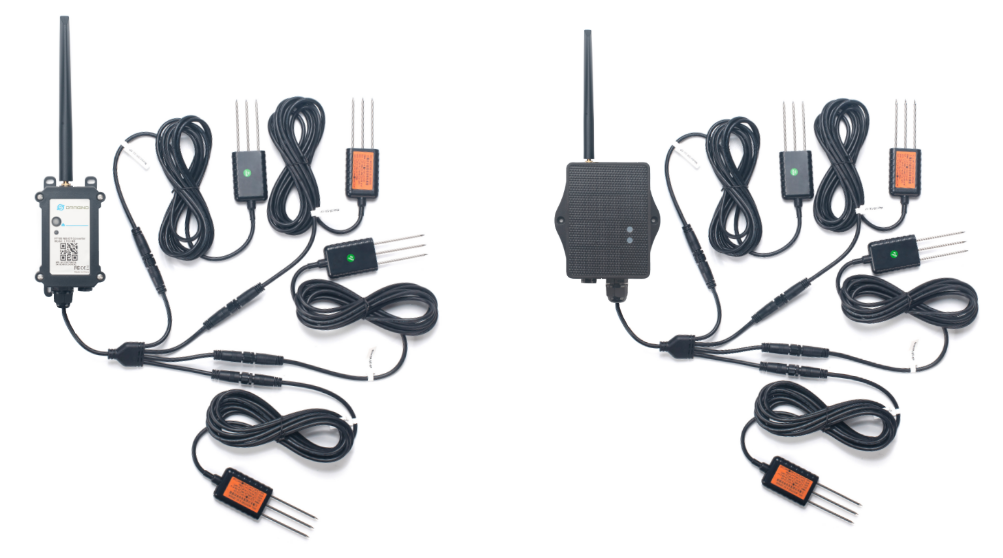
Table of Contents :
- 1. Introduction
- 2. Use SE0X-CB/CS to communicate with IoT Server
- 3. Configure SE0X-CB/CS
- 3.1 Configure Methods
- 3.2 Serial Access Password
- 3.3 AT Commands Set
- 3.4 Test Uplink and Change Update Interval
- 3.5 Working mode selection
- 3.6 Set the receiving time
- 3.7 Reset
- 3.8 +5V
- 3.9 Trigger an uplink by external interrupt
- 3.10 Set the QoS level
- 3.11 Set the TLS mode
- 3.12 Set GNSS open time
- 3.13 Turn on/off GPS
- 3.14 Set GPS positioning interval
- 3.15 Set the search network time
- 3.16 Set the IPv4 or IPv6
- 3.17 Configure Network Category to be Searched for under LTE RAT.
- 3.18 Factory data reset
- 3.19 Set CoAP option
- 3.20 Power on / power off BG95 module
- 3.21 Uplink log query
- 3.22 Setting the sensor address
- 3.23 Domain name resolution settings
- 3.24 Set the downlink debugging mode
- 3.25 Domain name resolution settings(Since firmware v1.1.1)
- 4. Battery & Power Consumption
- 5. Firmware update
- 6. FAQ
- 7. Order Info
- 8. Packing Info
- 9. Support
1. Introduction
1.1 What is SE0X-CB/CS NB-IoT/LTE-M Soil Moisture & EC Sensor
The Dragino SE0X-CB/CS is a NB-IoT/LTE-M Soil Moisture & EC Sensor for Agri-IoT with up to 4 sensor probes. It is designed to measure the soil moisture of saline-alkali soil and loamy soil. The soil sensor uses FDR method to calculate the soil moisture with the compensation from soil temperature and conductivity. It also has been calibrated in factory for Mineral soil type.
It detects Soil Moisture, Soil Temperature and Soil Conductivity, and then upload to IoT server via NB-IoT or CAT-M1 network.
SE0X-CB/CS supports different uplink methods include TCP, MQTT, UDP, MQTTs or CoAP for different application requirement. and Support Uplinks to various IoT Servers.
SE0X-CB/CS supports BLE configure and wireless OTA update which make user easy to use.
SE0X-CB/CS is powered by 8500mAh Li-SOCI2 battery or solar powered + Li-ion battery, it is designed for long-term use up to several years.

1.2 Features
- For -NB Bands: B1/B2/B3/B4/B5/B8/B12/B13/B17/B18/B19/B20/B25/B28/B66/B70/B85
- For -CB Bands: B1/B2/B3/B4/B5/B8/B12/B13//B18/B19/B20/B25/B28/B66/B71/B85
- CAT-M1 / LTE-M Bands: B1/B2/B3/B4/B5/B8/B12/B13/B18/B19/B20/B25/B26/B27/B28/B66/B85
- Ultra-low power consumption
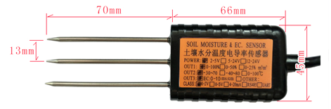
- Up to 4 external sensor probes, probe length: 2.5 meters
- Monitor Soil Moisture
- Monitor Soil Temperature
- Monitor Soil Conductivity
- IP66 Waterproof Enclosure
- Multiply Sampling and one uplink
- Uplink via MQTT, MQTTs, TCP, UDP or CoAP
- GNSS for Location Report
- Support Bluetooth v5.1 remote configure and update firmware
- Uplink on periodically
- Downlink to change configure
- 8500mAh Li/SOCl2 Battery (SE0X-CB)
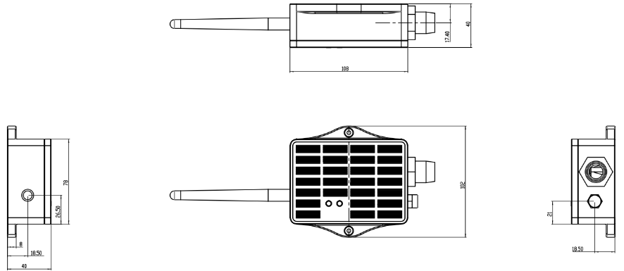
- Solar panel + 3000mAh Li-ion battery (SE0X-CS)
- Nano SIM card slot for NB-IoT SIM
Common DC Characteristics:
- Supply Voltage: Built-in Battery , 2.6v ~ 3.6v
- Operating Temperature: -40 ~ 85°C
Soil Moisture:
- Range: 0-100.00 V/V %
- Resolution: 0.01 V/V %
- Accuracy: ±3% (0-53%)V/V %, ±5% (>53%) V/V %
- Measure Method: FDR , with temperature &EC compensate
Soil Temperature
- Range: -40.00℃~85.00℃
- Resolution: 0.01℃
- Accuracy: -10℃~50℃:<0.3℃ ,All other: <0.6℃
- Measure Method: RTD, and calibrate
Soil Conductivity
- Range: 0-20000 uS/cm(25℃)(0-20.0EC)
- Resolution: 1 uS/cm
- Accuracy: 2%FS
- Measure Method: Conductivity , with temperature compensate
NB-IoT Spec:
NB-IoT Module: BG95-NGFF
Support Bands:
- B1 @H-FDD: 2100MHz
- B2 @H-FDD: 1900MHz
- B3 @H-FDD: 1800MHz
- B4 @H-FDD: 2100MHz
- B5 @H-FDD: 860MHz
- B8 @H-FDD: 900MHz
- B12 @H-FDD: 720MHz
- B13 @H-FDD: 740MHz
- B17 @H-FDD: 730MHz
- B18 @H-FDD: 870MHz
- B19 @H-FDD: 870MHz
- B20 @H-FDD: 790MHz
- B25 @H-FDD: 1900MHz
- B28 @H-FDD: 750MHz
- B66 @H-FDD: 2000MHz
- B70 @H-FDD: 2000MHz
- B85 @H-FDD: 700MHz
Battery:
- Li/SOCI2 un-chargeable battery
- Capacity: 8500mAh
- Self-Discharge: <1% / Year @ 25°C
- Max continuously current: 130mA
- Max boost current: 2A, 1 second
Power Consumption
- Sleep Mode: 5uA @ 3.3v
- LoRa Transmit Mode: 125mA @ 20dBm, 82mA @ 14dBm
1.4 Applications
- Smart Agriculture
1.5 Sleep mode and working mode
Deep Sleep Mode: Sensor doesn't have any NB-IoT/CAT-M1 activate. This mode is used for storage and shipping to save battery life.
Working Mode: In this mode, Sensor will work as NB-IoT Sensor to Join NB-IoT network and send out sensor data to server. Between each sampling/tx/rx periodically, sensor will be in IDLE mode), in IDLE mode, sensor has the same power consumption as Deep Sleep mode.
1.6 Button & LEDs

| Behavior on ACT | Function | Action |
|---|---|---|
 1~3s 1~3s | Send an uplink | If sensor has already attached to NB-IoT/CAT-M1 network, sensor will send an uplink packet, blue led will blink once. |
 >3s >3s | Active Device | Green led will fast blink 5 times, device will enter OTA mode for 3 seconds. And then start to attach NB-IoT/CAT-M1 network. |
 x5 x5 | Deactivate Device | Red led will solid on for 5 seconds. Means device is in Deep Sleep Mode. |
Note: When the device is executing a program, the buttons may become invalid. It is best to press the buttons after the device has completed the program execution.
1.7 BLE connection
SE0X-CB/CS support BLE remote configure and firmware update.
BLE can be used to configure the parameter of sensor or see the console output from sensor. BLE will be only activate on below case:
- Press button to send an uplink
- Press button to active device.
- Device Power on or reset.
If there is no activity connection on BLE in 60 seconds, sensor will shut down BLE module to enter low power mode.
1.8 Pin Definitions

1.8.1 Jumper JP2
Power on Device when put this jumper.
1.8.2 BOOT MODE / SW1
1) ISP: upgrade mode, device won't have any signal in this mode. but ready for upgrade firmware. LED won't work. Firmware won't run.
2) Flash: work mode, device starts to work and send out console output for further debug
1.8.3 Reset Button
Press to reboot the device.
1.8.4 SIM Card Direction
See this link. How to insert SIM Card.
1.9 Mechanical
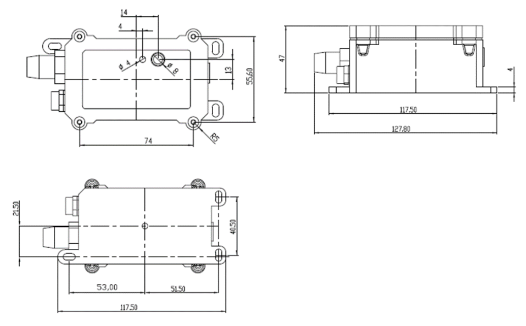
1.9.1 for CB version
Main Device Dimension:
Probe Dimension:
1.9.2 for CS version
1.10 Installation in Soil
Measurement the soil surface
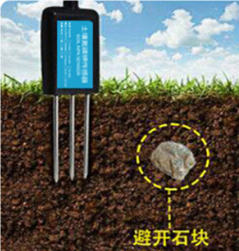
Choose the proper measuring position. Avoid the probe to touch rocks or hard things. Split the surface soil according to the measured deep. Keep the measured as original density. Vertical insert the probe into the soil to be measured. Make sure not shake when inserting.

Dig a hole with diameter > 20CM.
Horizontal insert the probe to the soil and fill the hole for long term measurement.
2. Use SE0X-CB/CS to communicate with IoT Server
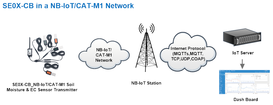
2.1 Send data to IoT server via NB-IoT network
The SE0X-CB/CS is equipped with a NB-IoT module, the pre-loaded firmware in SE0X-CB/CS will get environment data from sensors and send the value to local NB-IoT network via the NB-IoT module. The NB-IoT network will forward this value to IoT server via the protocol defined by SE0X-CB/CS.
Below shows the network structure:
There are two version: -GE and -1T version of SE0X-CB/CS.
GE Version: This version doesn't include SIM card or point to any IoT server. User needs to use AT Commands to configure below two steps to set SE0X-CB/CS send data to IoT server.
- Install NB-IoT SIM card and configure APN. See instruction of Attach Network.
- Set up sensor to point to IoT Server. See instruction of Configure to Connect Different Servers.
Below shows result of different server as a glance.
| Servers | Dash Board | Comments |
| Node-Red | 
| |
| DataCake | 
| |
| Tago.IO | ||
| General UDP | Raw Payload. Need Developer to design Dash Board | |
| General MQTT | Raw Payload. Need Developer to design Dash Board | |
| ThingSpeak | 
| |
| ThingsBoard | 
|
1T Version: This version has 1NCE SIM card pre-installed and configure to send value to ThingsEye. User Just need to select the sensor type in ThingsEyeand Activate SE0X-CB/CS and user will be able to see data in ThingsEye. See here for ThingsEye Config Instruction.
Soil Sensor Address Configuration
All soil sensors are shipped with default address 0x01.
Do not use the same address repeatedly on the same node, otherwise the data will conflict, so if you connect more than 1 sensor to the SE0X-CB/CS node, you need to follow the steps below to change the address (supported addresses: 01-04):
Step 1: Keep the default address 01 for the first sensor. No modification or operation is required.
Step 2: Connect the second sensor, and change its address to 02.
Step 3: Disconnect the second sensor, connect the third sensor, and change its address to 03.
Step 3: Repeat Step 3 to assign address 04 to the fourth sensor.
For details, see Configure Methods in 3.1 and Command Description in 3.22.
Connection:
- Wiring during sensor operation:

- Wiring when changing the sensor address:

Note: The yellow wire is only used when the address of the sensor is modified. After the address of the sensor is successfully modified, please disconnect the yellow cable and use tape to isolate the wire core to prevent the yellow wire from touching the motherboard element and causing a short circuit.
2.2 Payload Types
To meet different server requirement, SE0X-CB/CS supports different payload type.
Includes:
- General JSON format payload. (Type=5)
- HEX format Payload. (Type=0)
- ThingSpeak Format. (Type=1)
- ThingsBoard Format. (Type=3)
User can specify the payload type when choose the connection protocol. Example:
AT+PRO=1,0 // Use COAP Connection & hex Payload
AT+PRO=1,5 // Use COAP Connection & Json Payload
AT+PRO=2,0 // Use UDP Connection & hex Payload
AT+PRO=2,5 // Use UDP Connection & Json Payload
AT+PRO=3,0 // Use MQTT Connection & hex Payload
AT+PRO=3,5 // Use MQTT Connection & Json Payload
AT+PRO=4,0 // Use TCP Connection & hex Payload
AT+PRO=4,5 // Use TCP Connection & Json Payload
2.2.1 General Json Format(Type=5)
2.2.1.1 AT+CFGMOD=0(Default Mode)
This is the General Json Format. As below:
{"IMEI":"868508065605159","IMSI":"454312901015184","Model":"SE0X-CB","interrupt":0,"interrupt_level":0,"battery":3.22,"signal":17,"sensor_flag":"1111","water_soil1":40.32,"temp_soil1":19.33,"conduct_soil1":6716,"water_soil2":40.21,"temp_soil2":19.64,"conduct_soil2":6507,"water_soil3":36.35,"temp_soil3":19.67,"conduct_soil3":5858,"water_soil4":8.70,"temp_soil4":19.39,"conduct_soil4":2984,"time":"2025-01-20T08:01:12Z","latitude":0.000000,"longitude":0.000000,"gps_time":"1970-01-01T00:00:00Z"}
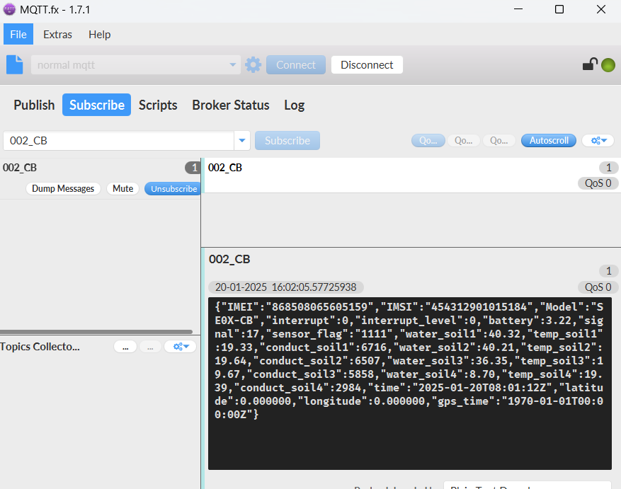
Notice, from above payload:
- interrupt, interrupt_level, battery, signal, sensor_flag, water_soil1, temp_soil1, conduct_soil1, water_soil2, emp_soil2, conduct_soil2, water_soil3, temp_soil3, onduct_soil3, water_soil4, temp_soil4,
conduct_soil4, time, Latitude, Longitude & gps_time are the value at uplink time.
2.2.1.2 AT+CFGMOD=1(Original value)
This is the General Json Format. As below:
{"IMEI":"868508065605159","IMSI":"454312901015184","Model":"SE0X-CB","interrupt":0,"interrupt_level":0,"battery":3.23,"signal":16,"sensor_flag":"1111","Soil_dielectric_constant1":24.2,"raw_water_soil1":4854,"raw_conduct_soil1":17217,"Soil_dielectric_constant2":28.8,"raw_water_soil2":5130,"raw_conduct_soil2":18958,"Soil_dielectric_constant3":19.5,"raw_water_soil3":4630,"raw_conduct_soil3":17580,"Soil_dielectric_constant4":1.0,"raw_water_soil4":2607,"raw_conduct_soil4":262,"time":"2025-01-20T10:06:27Z","latitude":0.000000,"longitude":0.000000,"gps_time":"1970-01-01T00:00:00Z"}
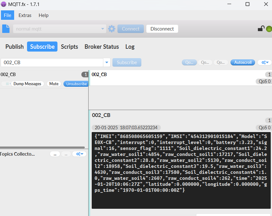
Notice, from above payload:
- interrupt, interrupt_level, battery, signal, sensor_flag, Soil_dielectric_constant1, raw_water_soil1, raw_conduct_soil1, Soil_dielectric_constant2, raw_water_soil2, raw_conduct_soil2,
Soil_dielectric_constant3, raw_water_soil3, raw_conduct_soil3, Soil_dielectric_constant4, raw_water_soil4, raw_conduct_soil4, time, Latitude, Longitude & gps_timeare the value at uplink time.
2.2.2 HEX format Payload(Type=0)
2.2.2.1 AT+CFGMOD=0(Default Mode)
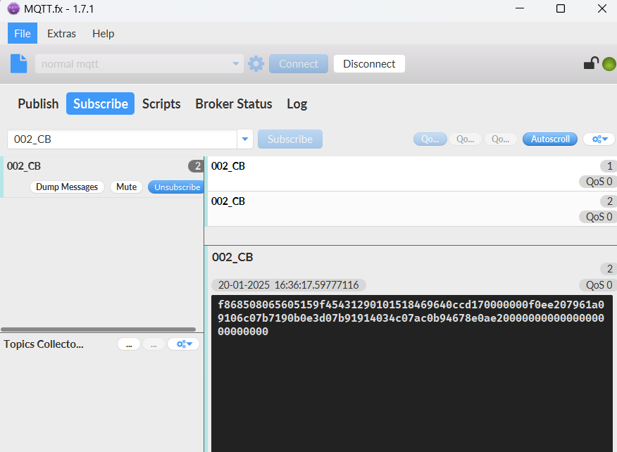
This is the HEX Format. As below:
f868508065605159f45431290101518469640ccd170000000f0ee207961a09106c07b7190b0e3d07b91914034c07ac0b94678e0ae2000000000000000000000000

If we use the MQTT client to subscribe to this MQTT topic, we can see the following information when the NB sensor uplink data.
Device ID(f+IMEI): f868508065605159 =868508065605159
SIM Card ID(f+IMSI): f454312901015184 =454312901015184
Version:
These bytes include the hardware and software version.
Higher byte: Specify Sensor Model: 0x69 for SE0X-CB/CS
Lower byte: Specify the software version: 0x64=100, means firmware version 1.0.0
BAT (Battery Info):
Ex1: 0x0CD1 = 3281mV
Signal Strength:
NB-IoT Network signal Strength.
Ex1: 0x17 = 23
0 -113dBm or less
1 -111dBm
2...30 -109dBm... -53dBm
31 -51dBm or greater
99 Not known or not detectable
MOD
This data field shows the current working mode.
Ex1: 0x00 default mode.
Ex2: 0x01 original mode.
Interrupt
This data field shows if this packet is generated by interrupt or not.
Example:
If byte[0]&0x01=0x00 : Normal uplink packet.
If byte[0]&0x01=0x01 : Interrupt Uplink Packet.
Interrupt_level:
This byte shows whether the interrupt is triggered by a high or low level.
Ex1: 0x00 Interrupt triggered by falling edge (low level)
Ex2: 0x01 Interrupt triggered by rising edge (high level)
Sensor_flag
Displays whether sensors are connected.
0: Sensor connection not detected.
1: Sensor connection detected.
For example, s_flag=1111,.Represents recognition to four sensors.
Counting from left to right,
The first number represents the 01 address sensor,
The second number represents the 02 address sensor;
The third number represents the 03 address sensor;
The fourth number represents the 04 address sensor.
Soil Moisture
Get the moisture content of the soil. The value range of the register is 0-10000(Decimal), divide this value by 100 to get the percentage of moisture in the soil.
For example, if the data you get from the register is 0x05 0xDC, the moisture content in the soil is 05DC(H) = 1500(D) /100 = 15%.
Soil Temperature
Get the temperature in the soil. The value range of the register is -4000 - +800(Decimal), divide this value by 100 to get the temperature in the soil. For example, if the data you get from the register is 0x09 0xEC, the temperature content in the soil is
Example:
If payload is 0105H: ((0x0105 & 0x8000)>>15 === 0),temp = 0105(H)/100 = 2.61 °C
If payload is FF7EH: ((FF7E & 0x8000)>>15 ===1),temp = (FF7E(H)-FFFF(H))/100 = -1.29 °C
Soil Conductivity (EC)
Obtain soluble salt concentration in soil or soluble ion concentration in liquid fertilizer or planting medium. The value range of the register is 0 - 20000(Decimal)( Can be greater than 20000).
For example, if the data you get from the register is 0x00 0xC8, the soil conductivity is 00C8(H) = 200(D) = 200 uS/cm.
Generally, the EC value of irrigation water is less than 800uS / cm.
TimeStamp:
Unit TimeStamp Example: 678B1740(H) = 1737168704(D)
Put the decimal value into this link(https://www.epochconverter.com)) to get the time.
Latitude:
EX1: 0x00000000 // Locating fails or is not enabled.
EX2: 0x015a771e(H)=22705950(D)=22.705950
Longitude:
EX1: 0x00000000 // Locating fails or is not enabled.
EX2: 0x114242500(H)=114242500(D)=114.242500
GPS_Timestamp:
EX1: 0x00000000 // The value is "1970-01-01T00:00:00Z" in JSON format. The initial GPS time is not refreshed if GPS positioning is disabled or fails.
EX2: 0x6682595d =1719818589 = 2024-07-01 15:23:09
2.2.2.2 AT+CFGMOD=1(Original value)
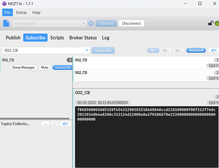
This is the HEX Format. As below:
f868508065605159f45431290101518469640ccd110100000f00f312f74dc20120140b4a8200c312134d12000a0a2f0106678e2139000000000000000000000000

If we use the MQTT client to subscribe to this MQTT topic, we can see the following information when the NB sensor uplink data.
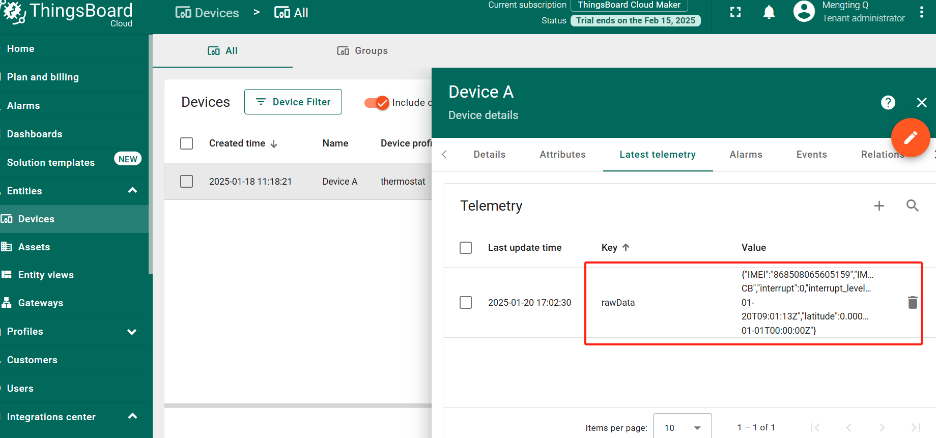
2.2.3 ThingsBoard Payload(Type=3)
2.2.3.1 AT+CFGMOD=0(Default Mode)
{
"IMEI": "868508065605159",
"IMSI": "454312901015184",
"Model": "SE0X-CB",
"interrupt": 0,
"interrupt_level": 0,
"battery": 3.27,
"signal": 21,
"sensor_flag": "1111",
"water_soil1": 39.07,
"temp_soil1": 19.51,
"conduct_soil1": 7301,
"water_soil2": 42.33,
"temp_soil2": 19.85,
"conduct_soil2": 6361,
"water_soil3": 36.5,
"temp_soil3": 19.81,
"conduct_soil3": 6783,
"water_soil4": 7.28,
"temp_soil4": 19.41,
"conduct_soil4": 2839,
"time": "2025-01-20T09:01:13Z",
"latitude": 0,
"longitude": 0,
"gps_time": "1970-01-01T00:00:00Z"
}
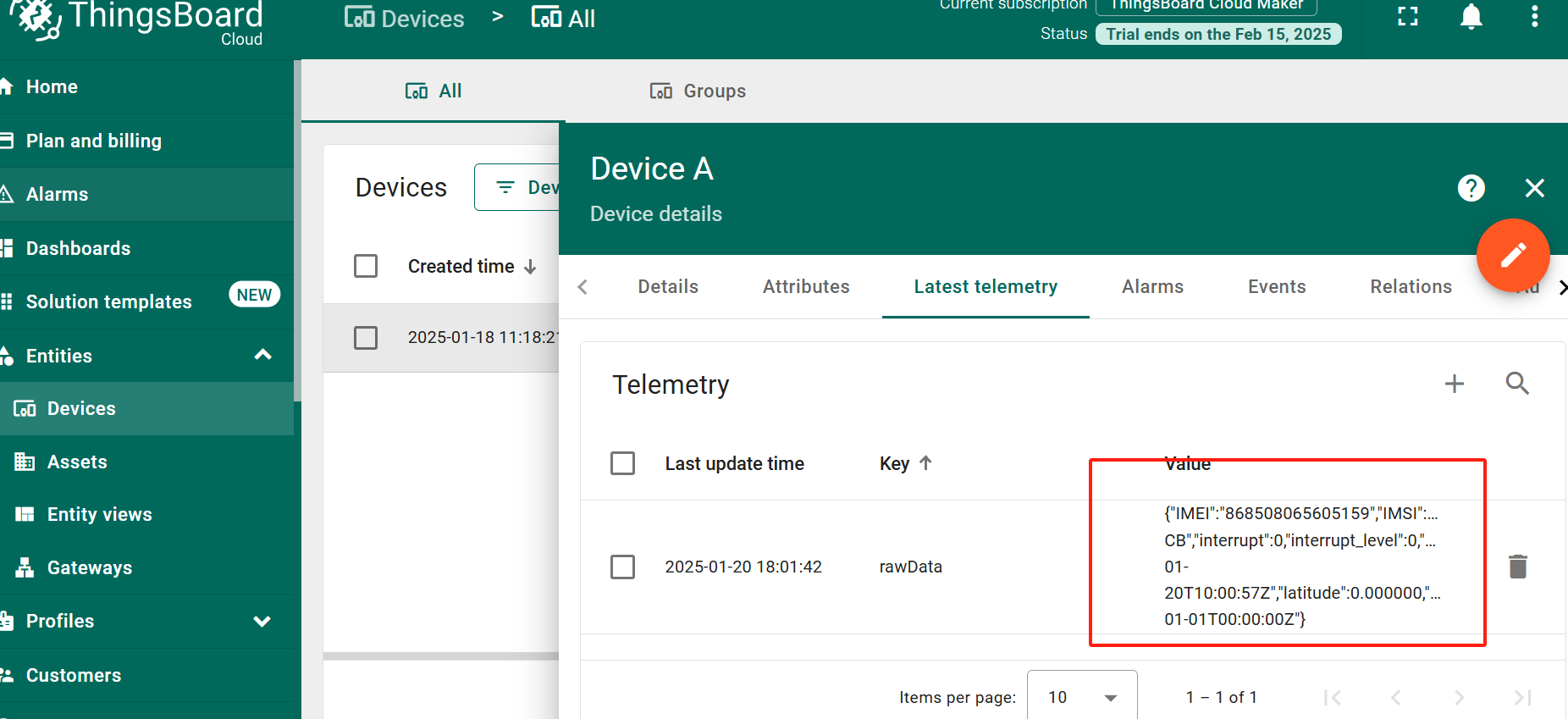
2.2.3.2 AT+CFGMOD=1(Original value)
{
"IMEI": "868508065605159",
"IMSI": "454312901015184",
"Model": "SE0X-CB",
"interrupt": 0,
"interrupt_level": 0,
"battery": 3.23,
"signal": 17,
"sensor_flag": "1111",
"Soil_dielectric_constant1": 24.2,
"raw_water_soil1": 4852,
"raw_conduct_soil1": 22367,
"Soil_dielectric_constant2": 28.8,
"raw_water_soil2": 5130,
"raw_conduct_soil2": 18293,
"Soil_dielectric_constant3": 19.5,
"raw_water_soil3": 4631,
"raw_conduct_soil3": 15702,
"Soil_dielectric_constant4": 1,
"raw_water_soil4": 2614,
"raw_conduct_soil4": 283,
"time": "2025-01-20T10:00:57Z",
"latitude": 0,
"longitude": 0,
"gps_time": "1970-01-01T00:00:00Z"
}
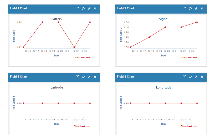
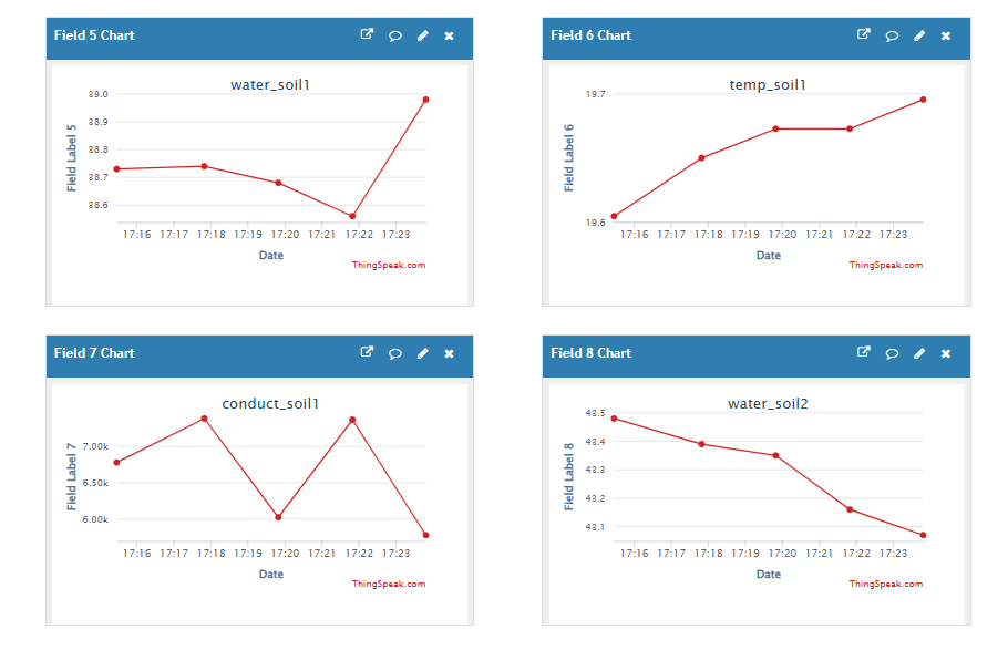
2.2.4 ThingSpeak Payload(Type=1)
This payload meets ThingSpeak platform requirement.
ThingSpeak only supports a maximum of 8 field charts per channel, so the sample screenshot contains only 8 fields charts.
2.2.4.1 AT+CFGMOD=0(Default Mode)
field1=Battery value&field2=Signal value&field3=latitude value&field4=longitude value&field5=water_soil1 value&field6=temp_soil1 value&field7=conduct_soil1 value&field8=water_soil2 value
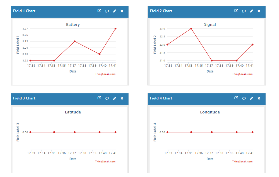
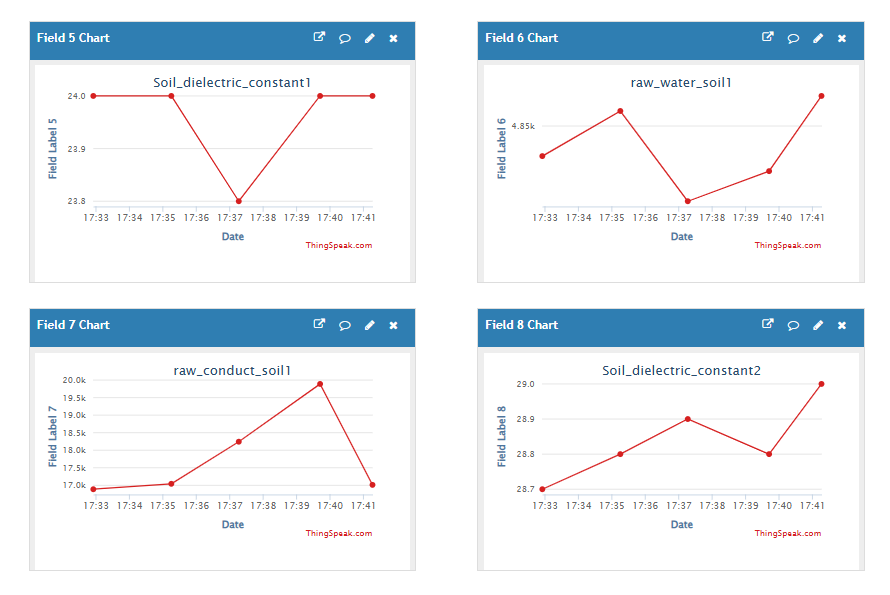
2.2.4.2 AT+CFGMOD=1(Original value)
field1=Battery value&field2=Signal value&field3=latitude value&field4=longitude value&field5=Soil_dielectric_constant1 value&field6=raw_water_soil1 value&field7=raw_conduct_soil1 value&field8=Soil_dielectric_constant2 value
3. Configure SE0X-CB/CS
3.1 Configure Methods
SE0X-CB/CS supports below configure method:
- AT Command via Bluetooth Connection (Recommended): BLE Configure Instruction.
- AT Command via UART Connection : See UART Connection.
3.2 Serial Access Password
After the Bluetooth or UART connection is successful, use the Serial Access Password to enter the AT command window.
The label on the box of the node will print the initial password: AT+PIN=xxxxxx, and directly use the six-digit password to access the AT instruction window.
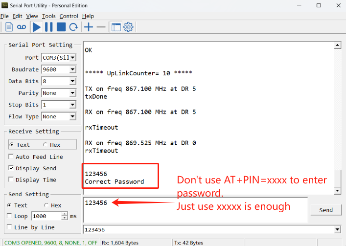
If you need to change the password, use AT+PWORD=xxxxxx (6 characters), -CB nodes only support lowercase letters.
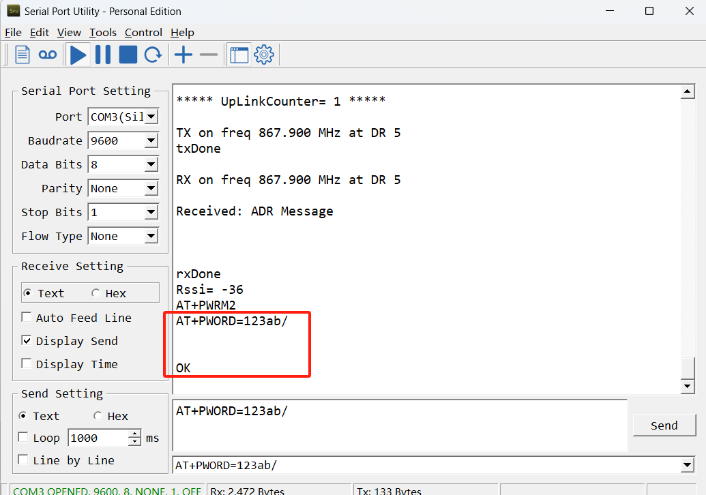
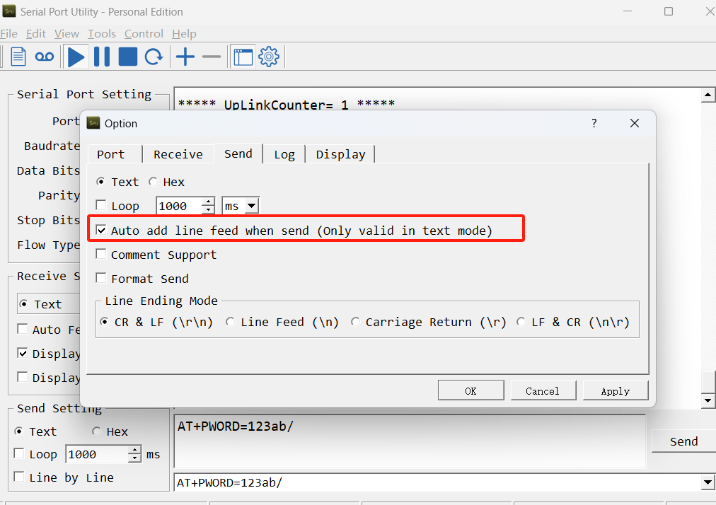
Note: After entering the command, you need to add a line break, and you can also set automatic line breaks in the Bluetooth tool or UART connection tool.
3.3 AT Commands Set
AT+<CMD>? : Help on <CMD>
AT+<CMD> : Run <CMD>
AT+<CMD>=<value> : Set the value
AT+<CMD>=? : Get the value
General Commands
AT+MODEL : Get module information
ATZ : Trig a reset of the MCU
AT+CFGMOD : Working mode selection
AT+DEUI : Get or set the Device ID
AT+SERVADDR: Get or Set the Server address
AT+TDC : Get or set the application data transmission interval in s
AT+INTMOD : Get or Set the trigger interrupt mode (0:input,1:falling or rising,2:falling,3:rising)
AT+APN : Get or set the APN
AT+5VT : Get or Set extend the time of 5V power
AT+PRO : Get or Set usage agreement (1:COAP,2:UDP,3:MQTT,4:TCP)
AT+RXDL : Get or Set the receiving time
AT+GETSENSORVALUE : Returns the current sensor measurement
AT+DNSCFG : Get or Set DNS Server
AT+CSQTIME : Get or Set the time to join the network
AT+GDNS : Get or Set the DNS
AT+SLEEP : Get or Set the sleep mode
AT+IPTYPE : Set the IPv4 or IPv6
AT+QSW : Power on and power off BG95 module
AT+QBAND: Get or set Frequency Band
AT+IOTMOD: Configure Network Category to be Searched for under LTE RAT
AT+DOWNTE: Get or set the conversion between the standard version and 1T version downlinks
AT+MADD: Change the sensor address to 0x01, 0x02, 0x03, 0x04
MQTT Management
AT+CLIENT : Get or Set the MQTT clientID
AT+UNAME : Get or Set the MQTT Username
AT+PWD : Get or Set the MQTT password
AT+PUBTOPIC: Get or set MQTT publishing topic
AT+SUBTOPIC: Get or set MQTT subscription topic
AT+MQOS : Set the QoS level of MQTT
AT+TLSMOD : Get or Set the TLS mode
COAP Management
AT+URI1: Get or set CoAP option 1
AT+URI2: Get or set CoAP option 2
AT+URI3: Get or set CoAP option 3
AT+URI4: Get or set CoAP option 4
AT+URI5: Get or set CoAP option 5
AT+URI6: Get or set CoAP option 6
AT+URI7: Get or set CoAP option 7
AT+URI8: Get or set CoAP option 8
GPS
AT+GNSST : Extend the time to turn on GNSS
AT+GPS : Turn off and on GPS
AT+GTDC : Get or set GPS positioning interval in units of h
Information
AT+FDR1 : Reset parameters to factory default values except for passwords
AT+FDR : Reset Parameters to Factory Default
AT+CFG : Print all settings
AT+PWORD : Get or set the System password
AT+LDATA : Get the last upload data
AT+GETLOG : Print serial port logs
3.4 Test Uplink and Change Update Interval
By default, Sensor will send uplinks every 2 hours.
User can use below commands to change the uplink interval.
AT Command: AT+TDC
Example: AT+TDC=7200 // Set Update Interval to 7200 seconds
Downlink Commands: 0x01
Format: Command Code (0x01) followed by 3 bytes.
Example: 12 hours= 43200 seconds 43200(D)=0xA8C0(H)
Downlink Payload: 01 00 A8 C0 // AT+TDC=43200, Set Update Interval to 12 hours.
Note: User can also push the button for more than 1 second to activate an uplink.
3.5 Working mode selection
Feature: Working mode selection.
AT command: AT+CFGMOD
| Command Example | Function |
|---|---|
| AT+CFGMOD=0 | Set the operating mode to the default mode |
| AT+CFGMOD=1 | Setting the operating mode to the original mode |
Downlink Command: 0x02
- Downlink command: 02 01 // Equal to AT+CFGMOD=0
- Downlink command: 02 02 // Equal to AT+CFGMOD=1
3.6 Set the receiving time
Feature: Extend the receiving time
AT Command: AT+RXDL
Example: AT+RXDL=1000 // Set the receiving time delay to 1000ms
Downlink Commands: 0x03
Format: Command Code (0x03) followed by 3 bytes.
Example: Downlink Payload: 03 00 03 E8 // AT+RXDL=1000
3.7 Reset
Feature: Trig a reset of the MCU.
AT Command: ATZ
Downlink Commands: 0x04FF
3.8 +5V
Feature: Set extend the time of 5V power.
AT Command: AT+5VT
Example: AT+5VT=2000 // Set extend the time of 5V power to 2000 ms
Downlink Commands: 0x05
Format: Command Code (0x05) followed by 3 bytes.
Example: Downlink Payload: 05 00 07 D0 // AT+5VT=2000
3.9 Trigger an uplink by external interrupt
SE0X-CB/CS has an external trigger interrupt function. Users can use the GPIO_EXTI pin to trigger the upload of data packets.
AT command:
- AT+INTMOD // Set the trigger interrupt mode
- AT+INTMOD=0 // Disable Interrupt
- AT+INTMOD=1 // Trigger by rising and falling edge
- AT+INTMOD=2 // Trigger by falling edge
- AT+INTMOD=3 // Trigger by rising edge
Downlink Commands: 0x06
Format: Command Code (0x06) followed by 3 bytes.
Example1: Downlink Payload: 06 00 00 01 // AT+INTMOD=1
Example2: Downlink Payload: 06 00 00 03 // AT+INTMOD=3
3.10 Set the QoS level
This command is used to set the QoS level of MQTT.
AT command:
- AT+MQOS=xx // 0~2
Downlink command: 0x07
Format: Command Code (0x07) followed by 1 byte.
Ex1: Downlink payload: 0x0700 // AT+MQOS=0
Ex2: Downlink payload: 0x0701 // AT+MQOS=1
3.11 Set the TLS mode
Refer to this link (MQTT Connection to send data to Tago.io)to use the TLS mode.
AT Command: AT+TLSMOD
Example 1: AT+TLSMOD=0,0 // Disable TLS Mode.
Example 2: AT+TLSMOD=1,0 // No authentication
AT+TLSMOD=1,1 // Perform server authentication
AT+TLSMOD=1,2 // Perform server and client authentication if requested by the remote server
Downlink command: 0x09
Format: Command Code (0x09) followed by 2 bytes.
Example1: Downlink Payload: 09 00 00 // AT+TLSMOD=0,0
Example2: Downlink Payload: 09 01 02 // AT+TLSMOD=1,2
3.12 Set GNSS open time
Extend the time to turn on GNSS. The automatic GPS location time is extended when the node is activated.
AT Command: AT+GNSST
Example: AT+GNSST=30 // Set the GPS positioning time to 30 seconds
Downlink command: 0x10
Format: Command Code (0x10) followed by 2 bytes.
Example: Downlink Payload: 10 00 1E // AT+GNSST=30
3.13 Turn on/off GPS
AT Command: AT+GPS
Ex1: AT+GPS=0 // Turn off GPS
Ex2: AT+GPS=1 // Turn on GPS
Downlink command: 0x11
Format: Command Code (0x11) followed by 1 byte.
Example: Downlink Payload: 11 01 // AT+GPS=1
3.14 Set GPS positioning interval
Feature: Set GPS positioning interval (unit: hour).
When GPS is enabled, the node automatically locates and uplinks each time it passes GTDC time after activation.
AT Command: AT+GTDC
Example: AT+GTDC=24 // Set the GPS positioning interval to 24h.
Downlink command: 0x12
Format: Command Code (0x12) followed by 3 bytes.
Example: 24 hours: 24(D)=0x18(H)
Downlink Payload: 12 00 00 18 // AT+GTDC=24
3.15 Set the search network time
Feature: Get or Set the time to join the network(unit: minutes).
AT Command: AT+CSQTIME
Example: AT+CSQTIME=10 // Set the search time to 10 minutes.
Downlink command: 0x13
Format: Command Code (0x13) followed by 1 byte.
Example: Downlink Payload: 13 0A // AT+CSQTIME=10
3.16 Set the IPv4 or IPv6
This command is used to set IP version.
AT Command:
- AT+IPTYPE=1 // IPv4
- AT+IPTYPE=2 // IPv6
3.17 Configure Network Category to be Searched for under LTE RAT.
AT Command: AT+IOTMOD=xx
xx: 0: eMTC
1: NB-IoT
2: eMTC and NB-IoT
3.18 Factory data reset
Two different restore factory Settings configurations.
AT command:
- AT+FDR // Reset Parameters to Factory Default.
- AT+FDR1 // Reset parameters to factory default values except for passwords.
3.19 Set CoAP option
Feature: Set CoAP option, follow this link to set up the CoaP protocol.
AT command: AT+URI1~AT+URI8
AT+URI1=11,"i" // "i/" indicates that the endpoint supports observation mode. In -CB products, fixed setting AT+URI1=11,"i"
AT+URI2=11,"CoAP endpoint URl" // 11 is a fixed parameter.
Example: i/13a35fbe-9515-6e55-36e8-081fb6aacf86
AT+URI1=11,"i"
AT+URI2=11,"13a35fbe-9515-6e55-36e8-081fb6aacf86"
--> If multiple groups of CoAP endpoint urls:
AT+URI3=11,"i"
AT+URI4=11,"CoAP endpoint URl"
This command sets the connection parameters of the COAP.
3.20 Power on / power off BG95 module
This command is used to power on and power off BG95 module.
- AT command: AT+QSW
The module is powered on after the command is sent for the first time, and powered off after the command is sent again.

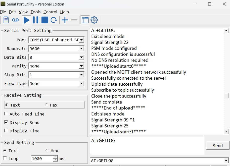
3.21 Uplink log query
- AT command: AT+GETLOG
This command can be used to query upstream logs of data packets.
3.22 Setting the sensor address
Function:Change the sensor address to 0x01, 0x02, 0x03, 0x04
(Note:When setting the address of the sensor, you need to connect the device individually for each one, and when modifying the address, you can't connect more than one sensor at the same time, otherwise it will be impossible to modify it, and when modifying it, you need to connect the yellow wire to VBAT_OUT, and after modifying it, you need to disconnect it.)
AT Command: AT+MADD
| Command Example | Function | Response |
|---|---|---|
| AT+MADD=1 | Set sensor address to 01 | Successfully modified sensor address to 0x01 OK |
| AT+MADD=2 | Set sensor address to 02 | Successfully modified sensor address to 0x02 OK |
Downlink Command:
No downlink command for this feature.
3.23 Domain name resolution settings
Feature: Set dynamic domain name resolution IP.
AT command: AT+BKDNS
| Command Example | Function/Parameters | Response/Explanation |
|---|---|---|
AT+BKDNS=? | Get current Settings | 0,0,NULL (default) |
AT+BKDNS=a,b,c | a: Enable/Disable dynamic domain name resolution. | 1: Disable dynamic domain name update. The ip address will be saved after the domain name is resolved, if the next domain name resolution fails, the last saved ip address will be used. 2: Enable dynamic domain name update. The ip address will be saved after domain name resolution, if the next domain name resolution fails, the last saved ip address will be used, and the domain name resolution will be updated regularly according to the time set by the customer. |
| b: Set the time to update the domain name resolution at regular intervals. | Unit: hour | |
c: Set the IP address manually. | The format is the same as AT+SERVADDR. |
Example:
- AT+BKDNS=1,0 // Dynamic domain name resolution is disabled.
- AT+BKDNS=2,1 // The dynamic domain name resolution function is enabled and the automatic update time is set to 1 hour.
- AT+BKDNS=2,4,3.69.98.183,1883 // The dynamic domain name resolution function is enabled and the automatic update time is set to 4 hour, and manually set the ip address, if the domain name failed to resolve, it will directly use this ip to communicate. When the next domain name resolution is successful, it will be updated to the ip address of the successful resolution.
Downlink Command:
No downlink commands for feature
3.24 Set the downlink debugging mode
Feature: Set the conversion between the standard version and 1T version downlinks.
AT command: AT+DOWNTE
| Command Example | Function/Parameters | Response/Explanation |
|---|---|---|
| AT+DOWNTE=? | Get current Settings | 0,0 (default) OK |
AT+DOWNTE=a,b | a: Set the conversion between the downlink of the standard version and 1T version | 0: Set the downlink of the standard version. |
| b: Enable/Disable downlink debugging | 0: Disable downlink debugging mode. |
Example:
- AT+DOWNTE=0,1 // Set to standard version downlink, and enable downlink debugging.
- AT+DOWNTE=1,1 // Set to 1T version downlink, and enable downlink debugging.
Downlink Command:
No downlink commands for feature
3.25 Domain name resolution settings(Since firmware v1.1.1)
Feature: Set static DNS resolution IP address.
AT command: AT+BKDNS
| Command Example | Function/Parameters | Response/Explanation |
|---|---|---|
AT+BKDNS=? | Get current Settings | 1,0,NULL (default) |
AT+BKDNS=a,b,c | a: Enable/Disable static DNS resolution. | 0: Disable static DNS resolution 1: Enable static DNS resolution. The ip address will be saved after the domain name is resolved, if the next domain name resolution fails, the last saved ip address will be used. |
| b: Meaningless. | Set to 0. | |
c: Set the IP address manually. | The format is the same as AT+SERVADDR. |
Example:
- AT+BKDNS=0,0,NULL //Disable static DNS resolution.
- AT+BKDNS=1,0,NULL // Enable static DNS resolution.
- AT+BKDNS=1,0,3.69.98.183,1883 //Enable static DNS resolution, if domain name resolution succeeds, the node uses the ip address successfully resolved and saves it to parameter c. If the domain name resolution fails, use the manually set ip address: 3.69.98.183 for communication.
Downlink Command:
No downlink commands for feature.
4. Battery & Power Consumption
SE0X-CB use ER26500 + SPC1520 battery pack and SE0X-NS use 3000mAh Recharable Battery with Solar Panel. See below link for detail information about the battery info and how to replace.
Battery Info & Power Consumption Analyze .
5. Firmware update
User can change device firmware to::
- Update with new features.
- Fix bugs.
Firmware and changelog can be downloaded from : Firmware download link
Methods to Update Firmware:
- (Recommended way) OTA firmware update via BLE: Instruction.
- Update through UART TTL interface : Instruction.
6. FAQ
6.1 AT Commands input doesn't work
In the case if user can see the console output but can't type input to the device. Please check if you already include the ENTER while sending out the command. Some serial tool doesn't send ENTER while press the send key, user need to add ENTER in their string.
6.2 Can I calibrate SE0X-CB/CS to different soil types?
SE0X-CB/CS can be used to measure EC/Moisture in different type of soil event concrete.
SE0X-CB/CS is calibrated for saline-alkali soil and loamy soil. If users want to use it for other soil, they can calibrate the value in the IoT platform base on the value measured by saline-alkali soil and loamy soil. The formula can be found at this link.
7. Order Info
Part Number: SE0X-CB/CS-XX
XX:
- GE: General version ( Exclude SIM card)
- 1T: with 1NCE * 10 years 500MB SIM card and Pre-configure to ThingsEye server
8. Packing Info
Package Includes:
- SE0X-CB/CS NB-IoT Soil Moisture & EC Sensor Transmitter
- External antenna x 1
Dimension and weight:
- Device Size: cm
- Device Weight: g
- Package Size / pcs : cm
- Weight / pcs : g
9. Support
- Support is provided Monday to Friday, from 09:00 to 18:00 GMT+8. Due to different timezones we cannot offer live support. However, your questions will be answered as soon as possible in the before-mentioned schedule.
- Provide as much information as possible regarding your enquiry (product models, accurately describe your problem and steps to replicate it etc) and send a mail to Support@dragino.cc.