General Configure/Commands to Connect to IoT server for -NB & -NS NB-IoT models
Table of Contents:
- 1. The use of this guideline
- 2. Attach Network
- 3. Configure to connect to different servers
- 3.1 General UDP Connection
- 3.2 General MQTT Connection
- 3.3 ThingSpeak (via MQTT)
- 3.4 Datacake
- 3.5 Node-Red (via MQTT)
- 3.6 ThingsBoard.Cloud (via MQTT)
- 3.7 ThingsBoard.Cloud (via COAP)
- 3.8 Tago.io (via MQTT)
- 3.9 TCP Connection
- 3.10 AWS Connection
- 3.11 ThingsEye (via MQTT)
- 4. MQTT/UDP/TCP downlink
- 5. FAQ
- 6. Trouble Shooting:
- 6.1 Checklist for debuging Network Connection issue. Signal Strenght:99 issue.
- 6.2 Issue: "NBIOT did not respond"
- 6.3 Issue: "Failed to readI MSI number"
- 6.4 Why sometime the AT Command is slow in reponse?
- 6.5 What is the Downlink Command Format for NB Devices?
- 6.6 How to get the debug log for further analyze?
- 6.7 How to find the AT Command Password if lost?
- 6.8
1. The use of this guideline
This configure instruction is for Dragino NB-IoT models with -NB or -NS suffix, for example DDS75-NB. These models use the same NB-IoT Module BC660K-GL and has the same software structure. The have the same configure instruction to different IoT servers. Use can follow the instruction here to see how to configure to connect to those servers.
2. Attach Network
2.1 General Configure to attach network
To attache NB-IoT sensors to NB-IoT Network, You need to:
- Get a NB-IoT SIM card from Service Provider. (Not the same as the SIM card we use in mobile phone)
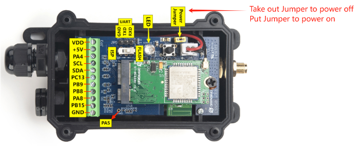
- Power Off End Node ( See below for the power off/on position)
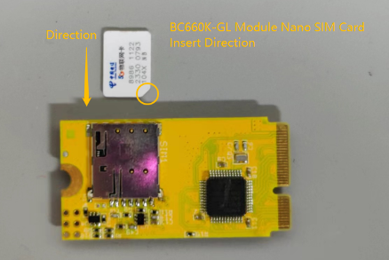
- Insert the SIM card to Sensor. ( See below for direction)
- Power On End Node
- Configure APN in the sensor (AT+APN=<APN>), example AT+APN=iot.1nce.net
After doing above, the NB-IoT Sensors should be able to attach to NB-IoT network .
The -NB and -NS models support LTE Cat NB2, with below frequency band: multiple frequency bands of B1/B2/B3/B4/B5/B8/B12/B13/B14/B17/B18/B19/B20/B25/B28/B66/B70/B85 . Make sure you use a the NB-IoT SIM card.
| SIM Provider | AT+APN= | NB-IoT Coverage | Comments |
| 1NCE | iot.1nce.net | Austria, Belgium, Bulgaria, Croatia, Czech Republic, Denmark, Finland, Germany, Great Britain, Greece, Hungary, Ireland, Italy, Latvia, Malta, Netherlands, Norway, Puerto Rico, Russia, Slovak , Republic, Slovenia, Spain, Sweden, Switzerland, Taiwan, USA, UK, US Virgin Islands | UK: Band20 |
| China Mobile | No need configure | China Mainland, HongKong | |
| China Telecom | ctnb | China Mainland |
| SIM Provider | AT+QCGDEFCONT= | Command Explanation | Comments |
| 1NCE/NB card purchased by the customer | iot.1nce.net/xxx | This command sets the PSD connection settings for PDN connection on power-up. When the MT attaches to the NB-IoT network on power-on, a PDN connection setup is performed. Therefore, PDN connection settings are stored in NVRAM so that they can be used by the modem during the attachment. |
2.2 Speed Up Network Attach time
BC660K-GL supports multi bands B1/B2/B3/B4/B5/B8/B12/B13/B14/B17/B18/B19/B20/B25/B28/B66/B70/B85. It will search one by one and try to attach, this will take a lot of time and even cause attach fail and show Signal Strenght:99. User can lock the band to specify band for its operator to make this faster.
AT+QBAND? // Check what is the current used frequency band
AT+QBAND=1,4 // Set to use 1 frequency band. Band4
Europe General AT+QBAND=2,8,20 // Set to use 2 frequency bands. Band 8 and Band 20
Global General : AT+QBAND=10,8,20,28,2,4,12,13,66,85,5
Verizon AT+QBAND=1,13
AT&T AT+QBAND=3,12,4,2
Telstra AT+QBAND=1,28
Softband AT+QBAND=2,3,8
After connection is successful, user can use AT+QENG=0 to check which band is actually in used.
By default, device will search network for 5 minutes. User can set the time to 10 minutes by AT+CSQTIME=10 so it can search longer.
See bands used for different provider: NB-IoT Deployment , Bands, Operator list
3. Configure to connect to different servers
3.1 General UDP Connection
The NB-IoT Sensor can send packet to server use UDP protocol.
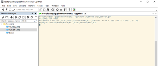
3.1.1 Simulate UDP Connection by PC tool
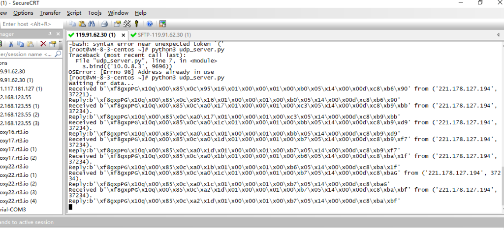
We can use PC tool to simulate UDP connection to make sure server works ok.
3.1.2 Configure NB-IoT Sensor
3.1.2.1 AT Commands
AT Commands:
- AT+PRO=2,0 // Set to use UDP protocol to uplink ,Payload Type select Hex payload
- AT+SERVADDR=120.24.4.116,5601 // Set UDP server address and port
3.1.2.2 Uplink Example
3.2 General MQTT Connection
The NB-IoT Sensor can send packet to server use MQTT protocol.
Below are the commands.
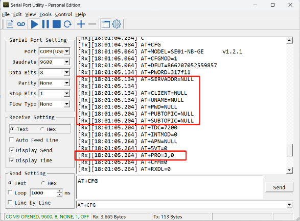
AT Commands:
- AT+PRO=3,0 // Set to use MQTT protocol to uplink, Payload Type select Hex payload.
- AT+SERVADDR=120.24.4.116,1883 // Set MQTT server address and port
- AT+CLIENT=CLIENT // Set up the CLIENT of MQTT
- AT+UNAME=UNAME // Set the username of MQTT
- AT+PWD=PWD // Set the password of MQTT
- AT+PUBTOPIC=NSE01_PUB // Set the sending topic of MQTT
- AT+SUBTOPIC=NSE01_SUB // Set the subscription topic of MQTT
Notice: MQTT protocol has a much higher power consumption compare with UDP/CoAP protocol. Please check the power analyze document and adjust the uplink period to a suitable interval.
3.3 ThingSpeak (via MQTT)
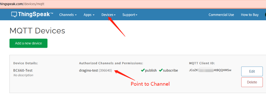
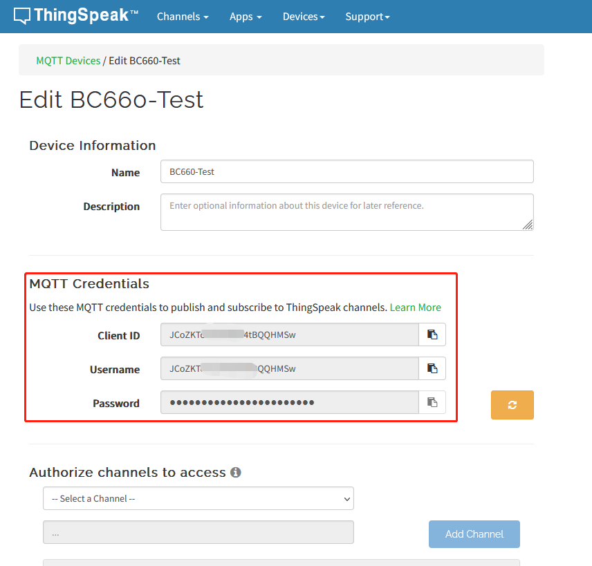
3.3.1 Get MQTT Credentials
ThingSpeak connection uses MQTT Connection. So we need to get MQTT Credentials first. You need to point MQTT Devices to ThingSpeak Channel as well.
3.3.2 Simulate with MQTT.fx
3.3.2.1 Establish MQTT Connection
After we got MQTT Credentials, we can first simulate with PC tool MQTT.fx tool to see if the Credentials and settings are fine.
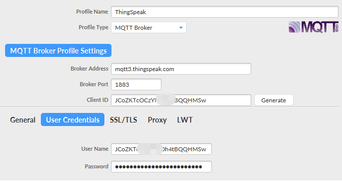
- Broker Address: mqtt3.thingspeak.com
- Broker Port: 1883
- Client ID: <Your ThingSpeak MQTT ClientID>
- User Name: <Your ThingSpeak MQTT User Name>
- Password: <Your ThingSpeak MQTT Password>
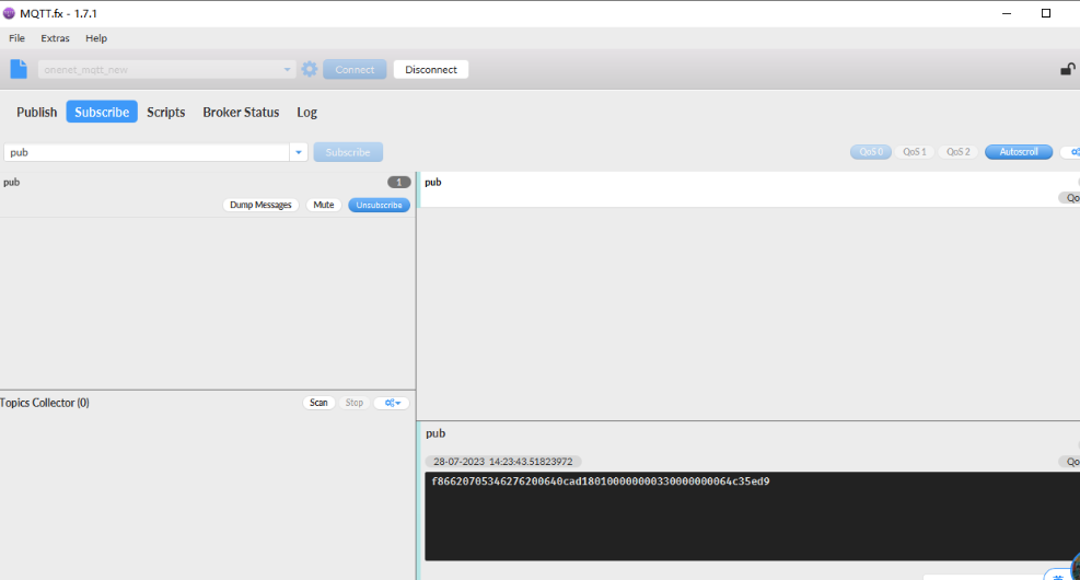
3.3.2.2 Publish Data to ThingSpeak Channel
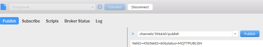
In MQTT.fx, we can publish below info:
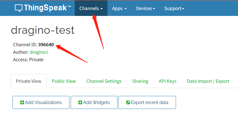
- Topic: channels/YOUR_CHANNEL_ID/publish
- Payload: field1=63&field2=67&status=MQTTPUBLISH
Where 63 and 67 are the value to be published to field1 & field2.
Result:
3.3.3 Configure NB-IoT Sensor for connection
3.3.3.1 AT Commands:
In the NB-IoT, we can run below commands so to publish the channels like MQTT.fx
- AT+PRO=3,1 // Set to use ThingSpeak Server and Related Payload
- AT+CLIENT=<Your ThingSpeak MQTT ClientID>
- AT+UNAME=<Your ThingSpeak MQTT User Name>
- AT+PWD=<Your ThingSpeak MQTT Password>
- AT+PUBTOPIC=<YOUR_CHANNEL_ID>
- AT+SUBTOPIC=<YOUR_CHANNEL_ID>
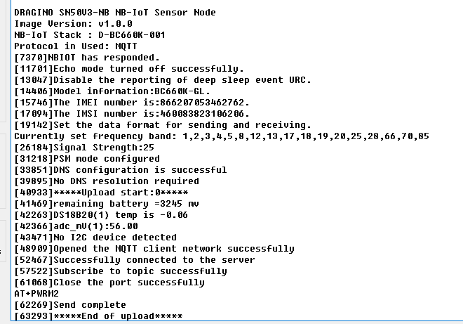
3.3.3.2 Uplink Examples
For SE01-NB
For DDS20-NB
For DDS45-NB
For DDS75-NB
For NMDS120-NB
For SPH01-NB
For NLM01-NB
For NMDS200-NB
For CPN01-NB
For DS03A-NB
For SN50V3-NB
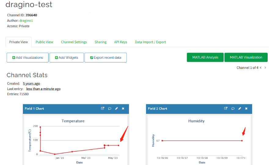
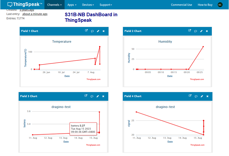
3.3.3.3 Map fields to sensor value
When NB-IoT sensor upload to ThingSpeak. The payload already specify which fileds related to which sensor value. Use need to create fileds in Channels Settings. with name so to see the value correctly.
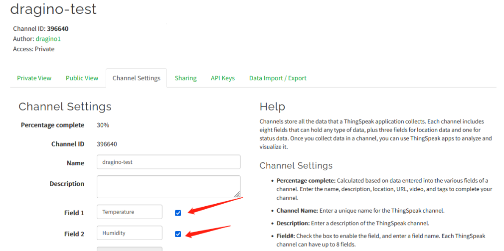
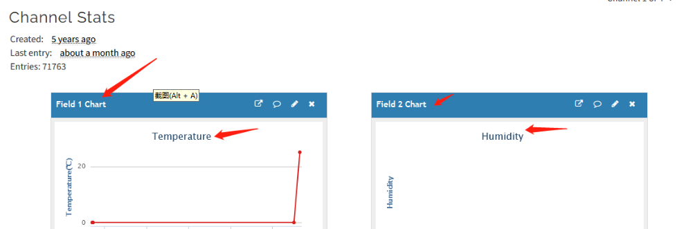
Below is the NB-IoT Product Table show the mapping.
| Field1 | Field2 | Field3 | Field4 | Field5 | Field6 | Field7 | Field8 | Field9 | Field10 | |
| S31x-NB | Temperature | Humidity | Battery | RSSI | ||||||
| SE01-NB | Temperature | Humidity | conduct | dielectric_constant | Battery | RSSI | ||||
| DDS20-NB | distance | Battery | RSSI | |||||||
| DDS45-NB | distance | Battery | RSSI | |||||||
| DDS75-NB | distance | Battery | RSSI | |||||||
| NMDS120-NB | distance | Battery | RSSI | |||||||
| SPH01-NB | ph | Temperature | Battery | RSSI | ||||||
| NLM01-NB | Humidity | Temperature | Battery | RSSI | ||||||
| NMDS200-NB | distance1 | distance2 | Battery | RSSI | ||||||
| CPN01-NB | alarm | count | door open duration | calc flag | Battery | RSSI | ||||
| DS03A-NB | level | alarm | pb14door open num | pb14 last open time | pb15 level status | pb15 alarm status | pb15 door open num | pb15 last open time | Battery | RSSI |
| SN50V3-NB mod1 | mod | Battery | RSSI | DS18B20 Temp | exit_state/input PA4 | adc0 | Temperature | Humidity | ||
| SN50V3-NB mod2 | mod | Battery | RSSI | DS18B20 Temp | exit_state/input PA4 | adc0 | distance | |||
| SN50V3-NB mod3 | mod | Battery | RSSI | adc0 | exit_state/input PA4 | adc1 | Temperature | Humidity | adc4 | |
| SN50V3-NB mod4 | mod | Battery | RSSI | DS18B20 Temp | adc0 | exit_state/input PA4 | DS18B20 Temp2 | DS18B20 Temp3 | ||
| SN50V3-NB mod5 | mod | Battery | RSSI | DS18B20 Temp | adc0 | exit_state/input PA4 | Weight | |||
| SN50V3-NB mod6 | mod | Battery | RSSI | count |
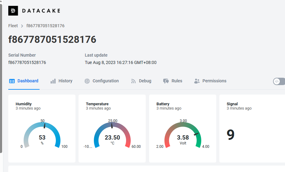
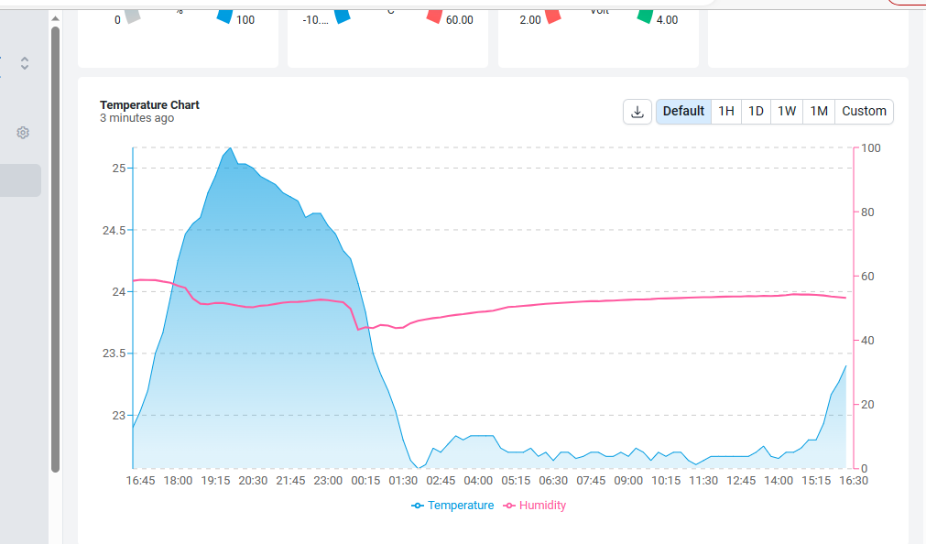
3.4 Datacake
Dragino NB-IoT sensors has its template in Datacake Platform. There are two version for NB Sensor,
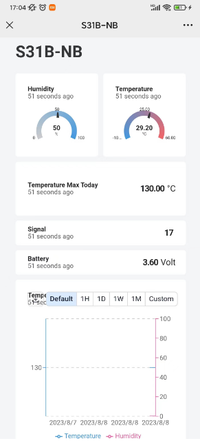
As example for S31B-NB. there are two versions: S31B-NB-1D and S31B-NB-GE.
- S31B-NB-1D: This version have pre-configure DataCake connection. User just need to Power on this device, it will auto connect send data to DataCake Server.
- S31B-NB-GE: This verson doesn't have pre-configure Datacake connection. User need to enter the AT Commands to connect to Datacake. See below for instruction.
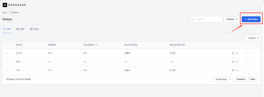
3.4.1 For device Already has template
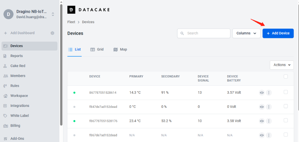
3.4.1.1 Create Device
Add Device in DataCake.
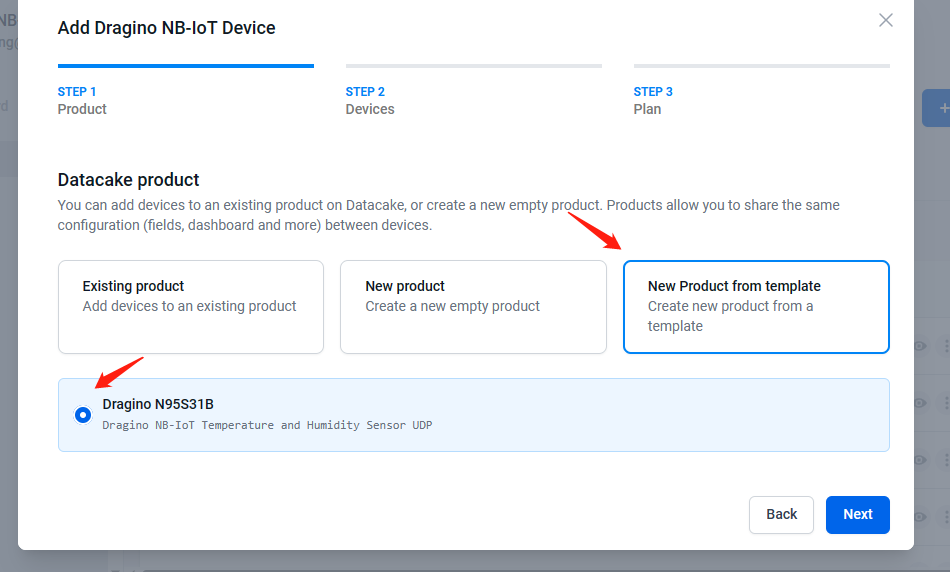
Choose the correct model from template.
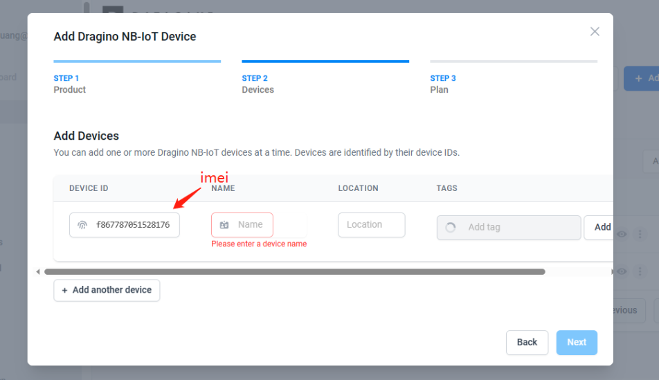
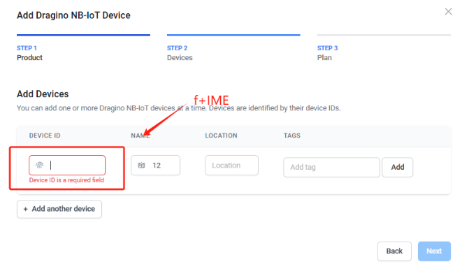
Fill Device ID. The device ID needs to be filled in with IMEI, and a prefix of 'f' needs to be added.
3.4.2 For Device already registered in DataCake before shipped
3.4.2.1 Scan QR Code to get the device info
Users can use their phones or computers to scan QR codes to obtain device data information.

3.4.2.2 Claim Device to User Account
By Default, the device is registered in Dragino's DataCake Account. User can Claim it to his account.
3.4.3 Manual Add Decoder in DataCake ( don't use the template in DataCake)
Step1: Add a device
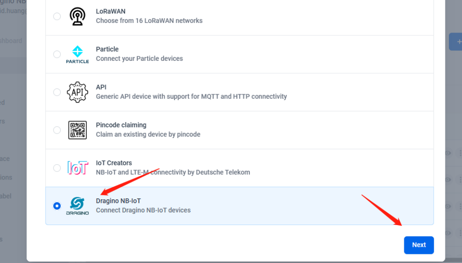
Step2: Choose your device type,please select dragino NB-IOT device
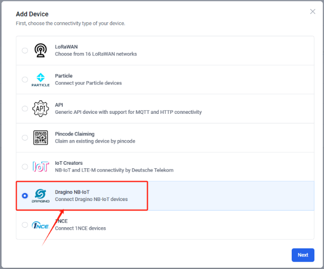
Step3: Choose to create a new device
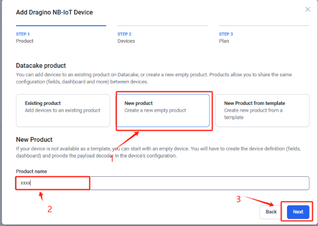
Step4: Fill in the device ID of your NB device
Step5: Please select your device plan according to your needs and complete the creation of the device

Step6: Please add the decoder at the payload decoder of the device configuration.
Decoder location: dragino-end-node-decoder/Datacake-Dragino_NB at main · dragino/dragino-end-node-decoder (github.com)
Due to version update, please use the following decoder for the new version firmware:
dragino-end-node-decoder/Datacake-Dragino_NB_New_Version at main · dragino/dragino-end-node-decoder (github.com)
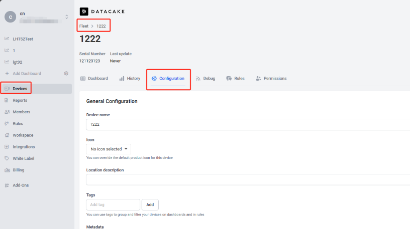
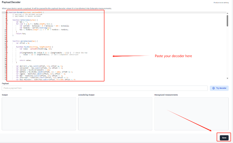
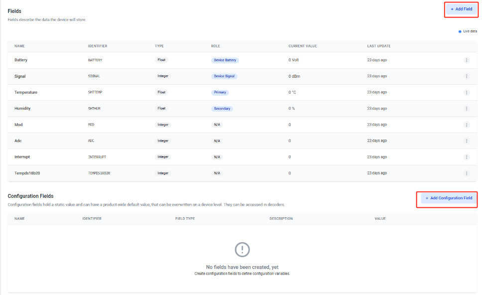
Step7: Add the output of the decoder as a field
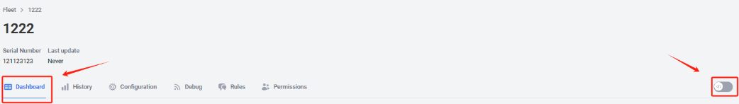
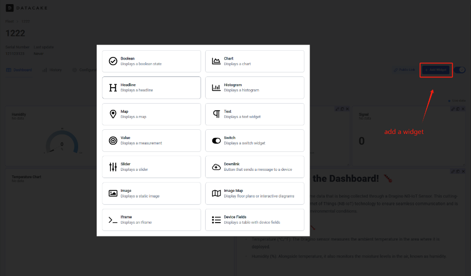
Step8: Customize the dashboard and use fields as parameters of the dashboard
3.4.4 For device have not configured to connect to DataCake
Use AT command for connecting to DataCake
AT+PRO=2,0
AT+SERVADDR=67.207.76.90,4445
3.5 Node-Red (via MQTT)
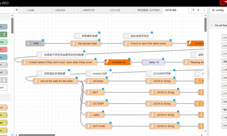
3.5.1 Configure Node-Red
Take S31-NB UDP protocol as an example.
Dragino provides input flow examples for the sensors.
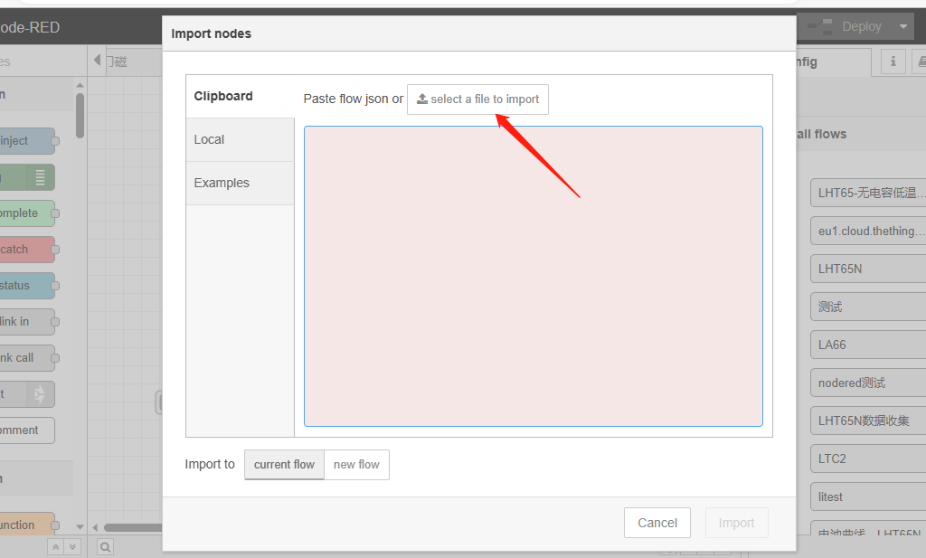
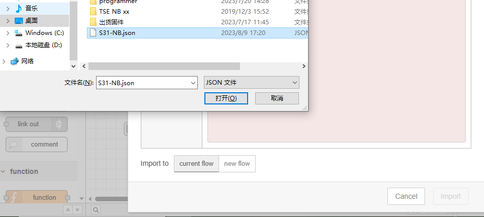
User can download the required JSON file through Dragino Node-RED input flow template.
Download sample JSON file link: https://www.dropbox.com/sh/mduw85jcuwsua22/AAAvwPhg9z6dLjJhmZjqBf_ma?dl=0
We can directly import the template.
The templates for S31-NB and NB95S31B are the same.
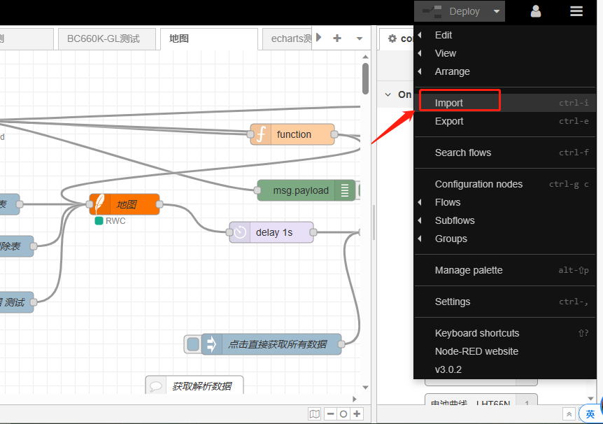
Please select the NB95S31B template.
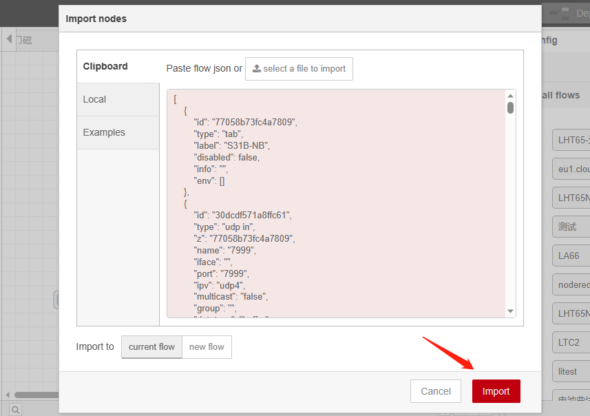
Successfully imported template.
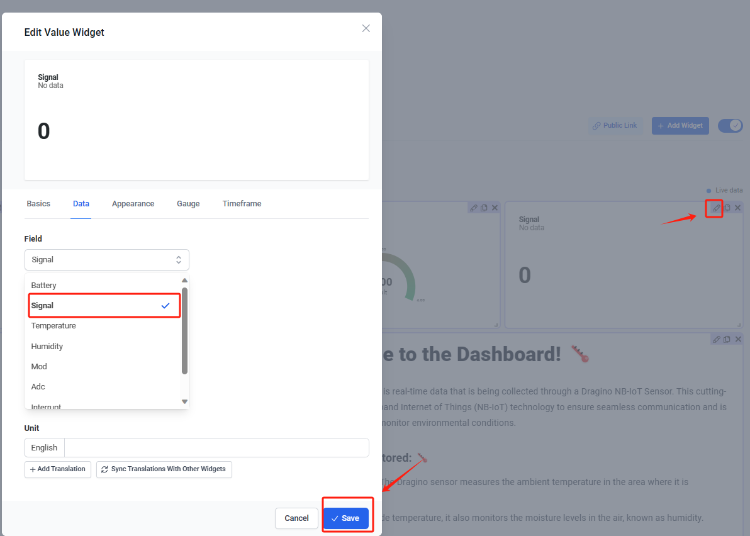
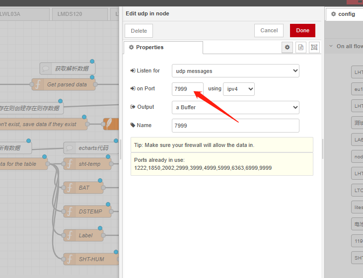
Users can set UDP port.
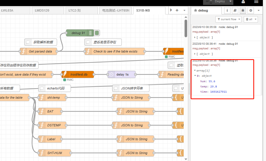
3.5.2 Simulate Connection
We have completed the configuration of UDP. We can try sending packets to node red.
3.5.3 Configure NB-IoT Sensors
- AT+PRO=3,0 or 3,5 // hex format or json format
- AT+SUBTOPIC=<device name>or User Defined
- AT+PUBTOPIC=<device name>or User Defined
- AT+CLIENT=<device name> or User Defined
- AT+UNAME=<device name> or User Defined
- AT+PWD=“Your device token”
3.6 ThingsBoard.Cloud (via MQTT)
3.6.1 Configure ThingsBoard
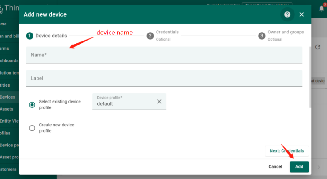
3.6.1.1 Create Device
Create a New Device in ThingsBoard. Record Device Name which is used for MQTT connection.
3.6.1.2 Create Uplink & Downlink Converter
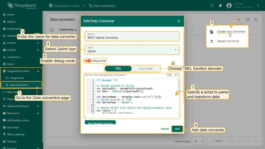
Uplink Converter
The purpose of the decoder function is to parse the incoming data and metadata to a format that ThingsBoard can consume. deviceName and deviceType are required, while attributes and telemetry are optional. Attributes and telemetry are flat key-value objects. Nested objects are not supported.
To create an uplink converter go to the Integrations center -> Data converters page and click “plus” button. Name it “MQTT Uplink Converter” and select type "Uplink". Use debug mode for now.
Downlink Converter
The Downlink converter transforming outgoing RPC message and then the Integration sends it to external MQTT broke
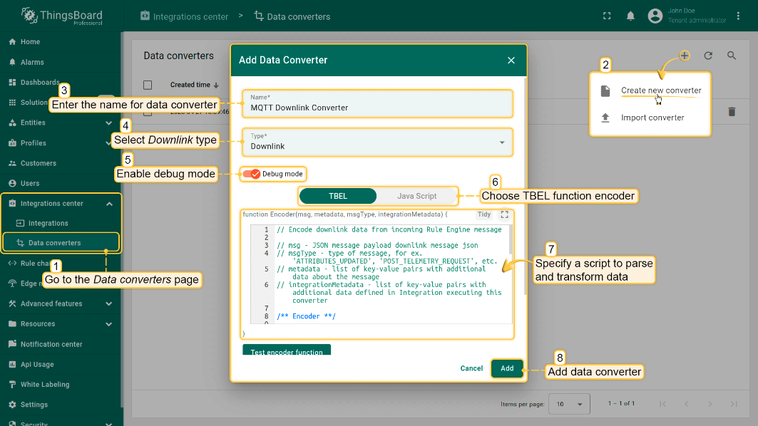
Note: Our device payload is already human readable data. Therefore, users do not need to write decoders. Simply create by default.
3.6.1.3 MQTT Integration Setup
Go to the Integrations center -> Integrations page and click “plus” icon to add a new integration. Name it “MQTT Integration”, select type MQTT;
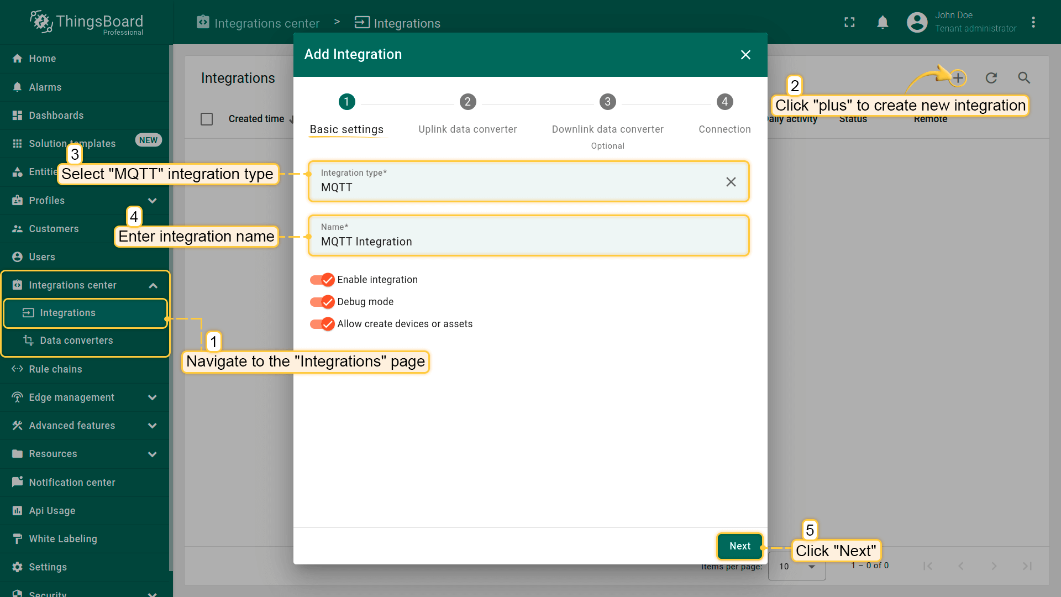
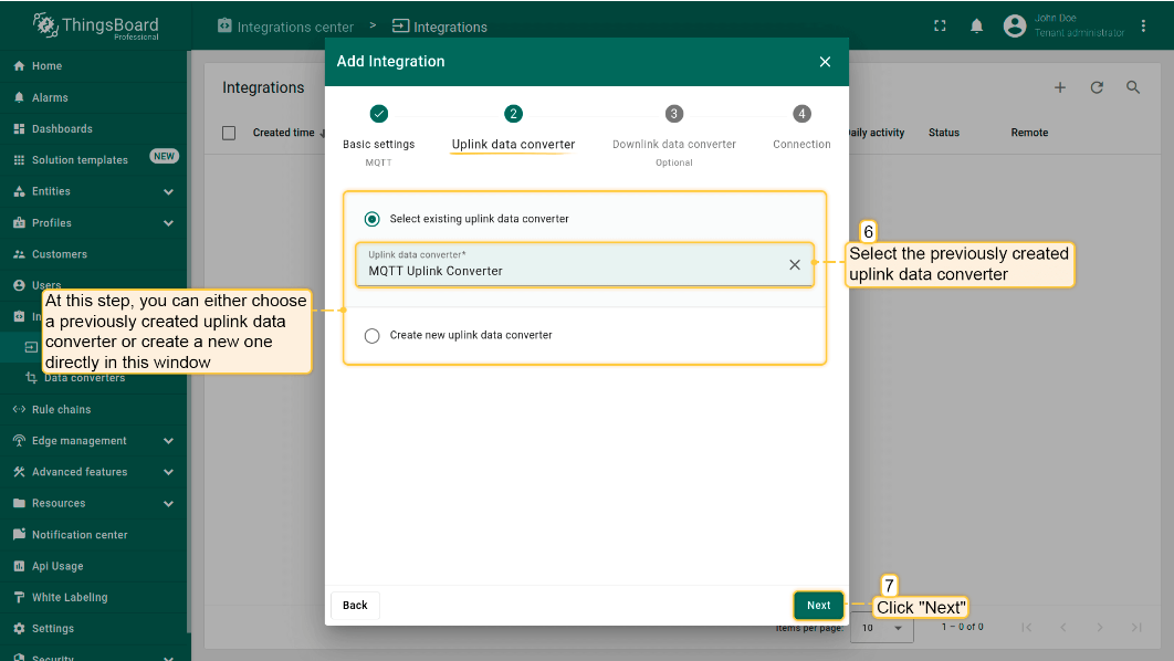
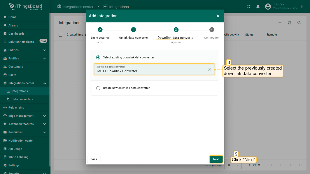
- The next steps is to add the recently created uplink and downlink converters;
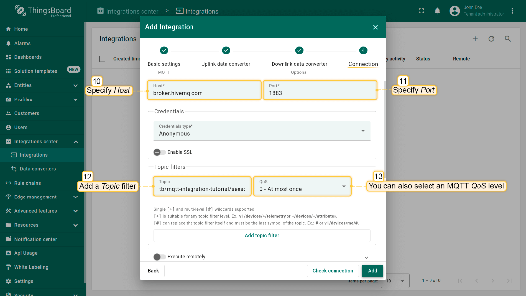
Add a topic filter:
Consistent with the theme of the node setting.
You can also select an MQTT QoS level. We use MQTT QoS level 0 (At most once) by default;
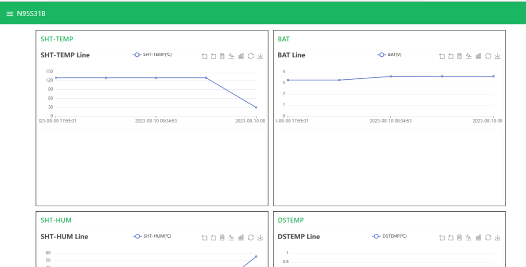
3.6.2 Simulate with MQTT.fx
3.6.3 Configure NB-IoT Sensor
AT Commands
- AT+PRO=3,3 // Use MQTT to connect to ThingsBoard. Payload Type set to 3.
- AT+SUBTOPIC=<device name>
- AT+PUBTOPIC=<device name>
- AT+CLIENT=<device name> or User Defined
- AT+UNAME=<device name> or User Defined
- AT+PWD=<device name> or User Defined
Test Uplink by click the button for 1 second
3.7 ThingsBoard.Cloud (via COAP)
3.7.1 Configure ThingsBoard
3.7.1.1 Create Uplink & Downlink Converter
Uplink Converter
The purpose of the decoder function is to parse the incoming data and metadata to a format that ThingsBoard can consume. deviceName and deviceType are required, while attributes and telemetry are optional. Attributes and telemetry are flat key-value objects. Nested objects are not supported.
To create an uplink converter go to the Integrations center -> Data converters page and click “plus” button. Name it “COAP Uplink Converter” and select type "Uplink". Use debug mode for now.

Downlink Converter
The Downlink converter transforming outgoing RPC message and then the Integration sends it to external COAP broker.

3.7.1.2 COAP Integration Setup
Go to the Integrations center -> Integrations page and click “plus” icon to add a new integration. Name it “CoAP Integration”, select type COAP ;

The next steps is to add the recently created uplink converters;

3.7.1.3 Add COAP Integration

3.7.2 Node Configuration(Example: Connecting to the Thingsboard platform)
3.7.2.1 Instruction Description
- AT+PRO=1,0(HEX format uplink) &AT+PRO=1,5(JSON format uplink)
- AT+SERVADDR=COAP Server Address,5683
Example: AT+SERVADDR=int.thingsboard.cloud,5683(The address is automatically generated when the COAP integration is created)

Note:The port for the COAP protocol has been fixed to 5683
- AT+URI1=11,character length,"Needs to be consistent with the CoAP endpoint URL in the platform",
-NB/NS products use the BC660K module, only need to configure only one URL command.
e.g.
- AT+URI1=11,38, "i/faaaa241f-af4a-b780-4468-c671bb574858"

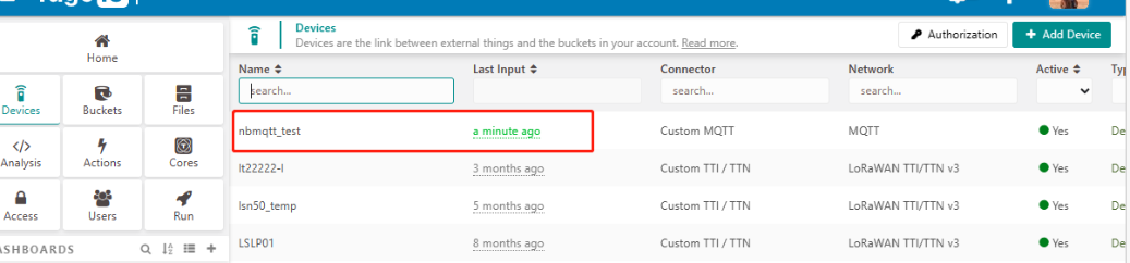
3.8 Tago.io (via MQTT)
3.8.1 Create device & Get Credentials
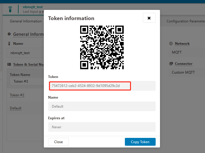
We use MQTT Connection to send data to Tago.io. We need to Create Device and Get MQTT Credentials first.
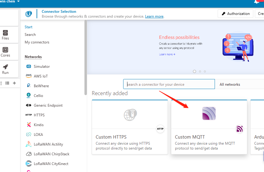
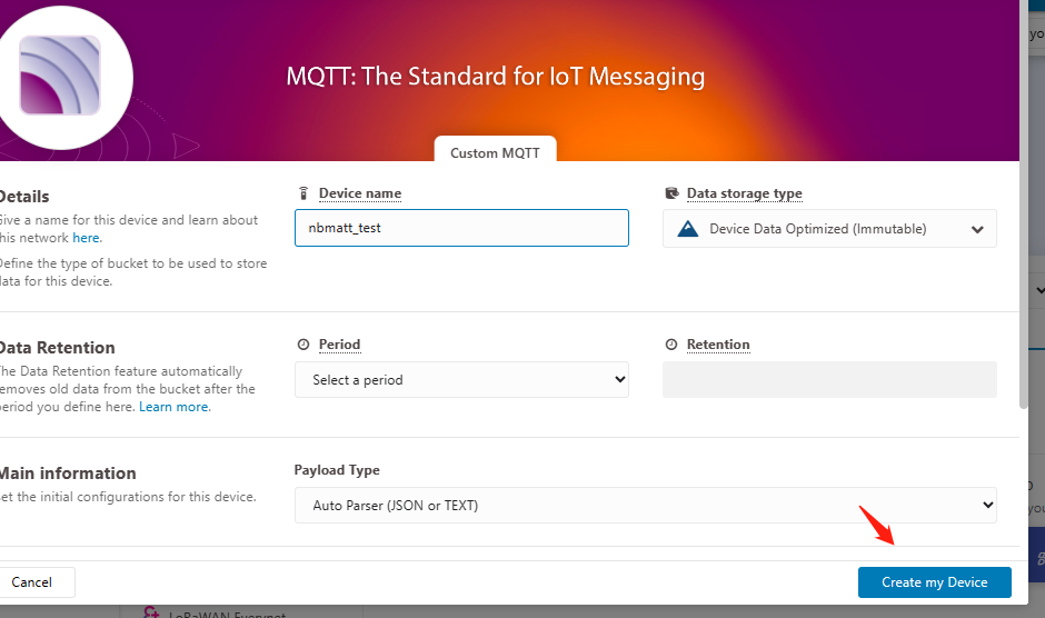
Go to the Device section and create a device. Then, go to the section tokens and copy your device-token.
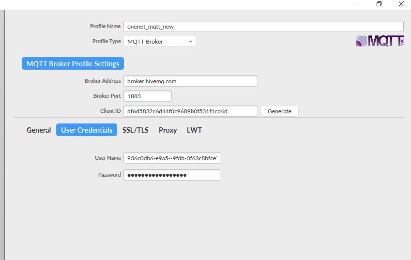
The device needs to enable the TLS mode and set the AT+TLSMOD=1,0 command.
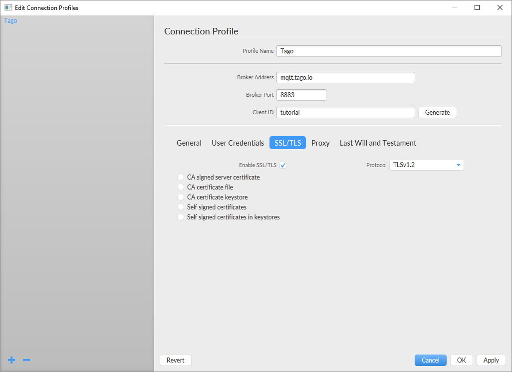
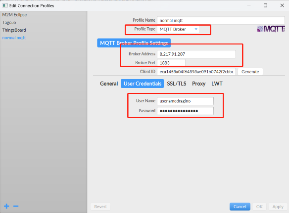
On the Connection Profile window, set the following information:
- Profile Name: “Any name”
- Broker Address: mqtt.tago.io
- Broker Port: 8883
- Client ID: “Any value”
On the section User credentials, set the following information:
- User Name: “Any value” // Tago validates your user by the token only
- Password: “Your device token”
- PUBTOPIC: “Any value”
- SUBTOPIC: “Any value”
AT command:
- AT+PRO=3,0 or 3,5 // hex format or json format
- AT+SUBTOPIC=<device name>or User Defined
- AT+PUBTOPIC=<device name>or User Defined
- AT+CLIENT=<device name> or User Defined
- AT+UNAME=<device name> or User Defined
- AT+PWD=“Your device token”
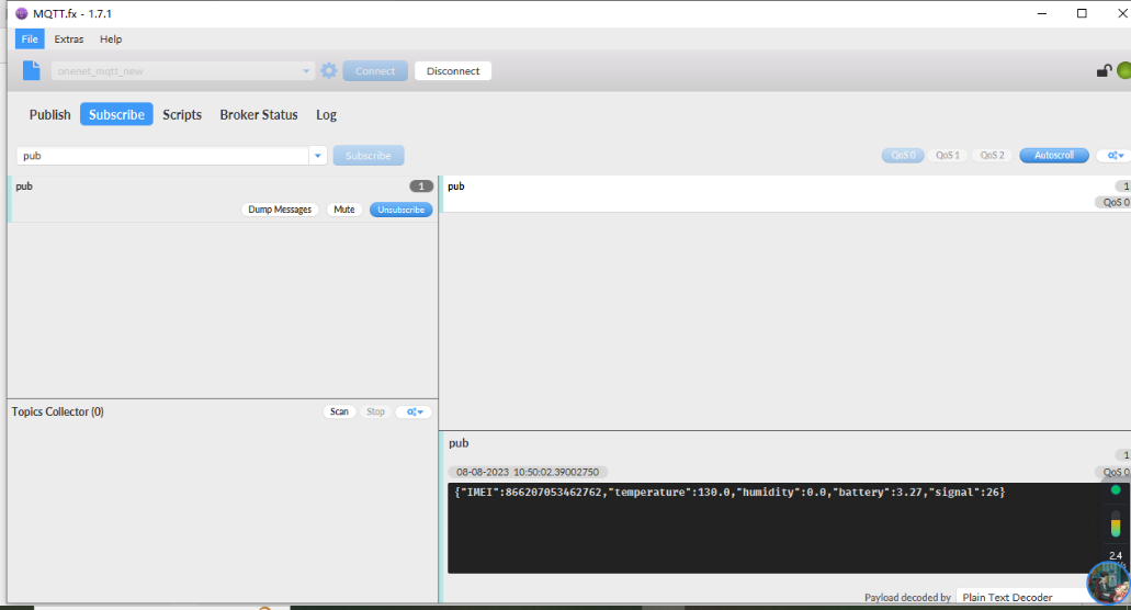
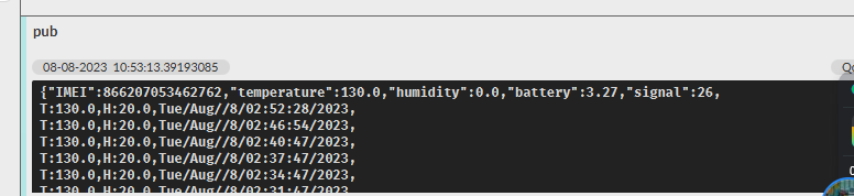
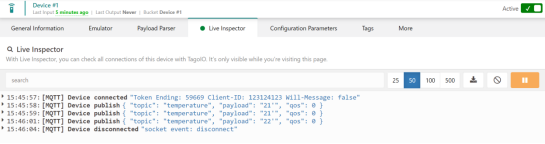
3.8.2 Simulate with MQTT.fx
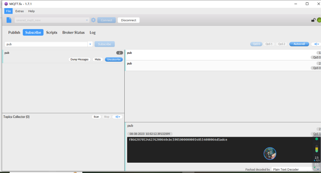
Users can run the AT+PRO=3,5 command, and the payload will be converted to JSON format.
3.8.3 tago data
3.9 TCP Connection
AT command:
- AT+PRO=4,0 // Set to use TCP protocol to uplink(HEX format)
- AT+PRO=4,1 // Set to use TCP protocol to uplink(JSON format)
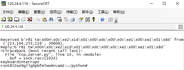
- AT+SERVADDR=120.24.4.116,5600 // to set TCP server address and port
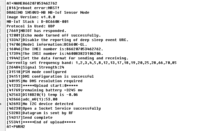
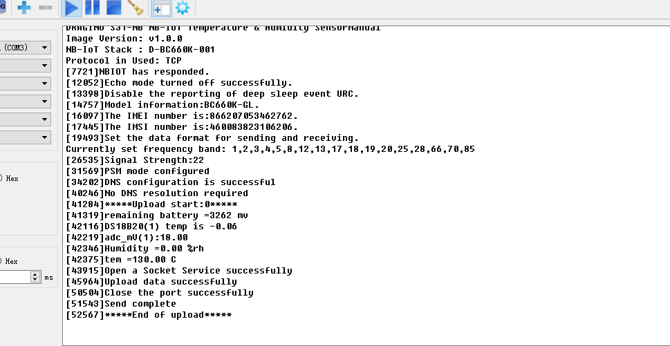
Sensor Console Output when Uplink:
See result in TCP Server:
3.10 AWS Connection
Users can refer to Dragino NB device connection to AWS platform instructions
3.11 ThingsEye (via MQTT)
3.11.1 Configure ThingsEye
3.11.1.1 Create MQTT integration
Go to the Integrations center -> Integrations page and click “plus” icon to add a new integration. Name it “MQTT Integration_NB”, select type MQTT;

Next, directly select to create a new Uplink data converter and downlink data converter.


Add a topic filter:
Consistent with the theme of the node setting.
Note: Recommended MQTT broker: lns1.thingseye.io 8883, fixed use. Topic can be changed on their own, but it need to be consistent with the node's publish and subscribe topic.
You can also select an MQTT QoS level. We use MQTT QoS level 0 (At most once) by default;

3.11.1.2 Add credentials to the MQTT integration
Click on the MQTT integration you just created.

Click the edit icon in the upper right corner to enter the edit mode.

Add credential files.
Click this link to download the certificates.

When the addition is complete, save the Settings.


3.11.1.3 Setup uplink and downlink converters
First, you need to download the MQTT uplink/downlink JS code.
- Uplink Converter
The purpose of the decoder function is to parse the incoming data and metadata to a format that ThingsBoard can consume.
Go to the Integrations center -> Data converters page, and find that MQTT uplink converter that was newly created when the integration was created.

Enter edit mode and apply MQTT uplink JS code to this uplink converter.

- Downlink Converter
Go to the Integrations center -> Data converters page, and find that MQTT downlink converter that was newly created when the integration was created.

Enter edit mode and apply MQTT downlink JS code to this downlink converter.

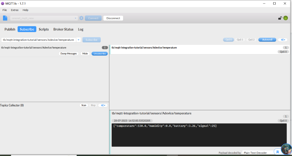
3.11.2 Simulate with MQTT.fx


3.11.3 Configure -NB node
First you need to configure the certificate to the -NB node. Follow the instructions in this link to configure the certificate.
Screenshot of successful certificate configuration:
- Configuring the CA Certificate


- Configure client certificate


- Configure client private key

When the certificate is configured, burn the boot program, burn the working firmware, and then restart the device.
Then configure the -NB node to connect to the ThingsEye platform:
AT Commands
- AT+PRO=3,5 // Use MQTT Connection & Json Payload
- AT+SERVADDR=lns1.thingseye.io,8883
- AT+SUBTOPIC=8899 // Consistent with the Topic of MQTT integration created by ThingsEye
- AT+PUBTOPIC=8899 // Consistent with the Topic of MQTT integration created by ThingsEye
- AT+CLIENT=NULL
- AT+UNAME=NULL
- AT+PWD=NULL
- AT+TLSMOD=1,2
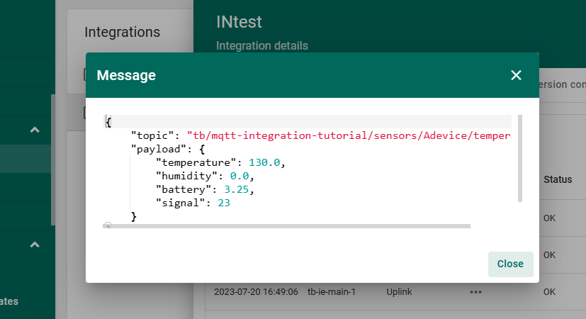
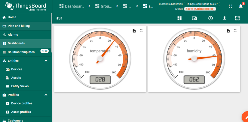
Test Uplink by click the button for 1~3 seconds, the MQTT integration in ThingsEye allows you to view the data upstream from the device:


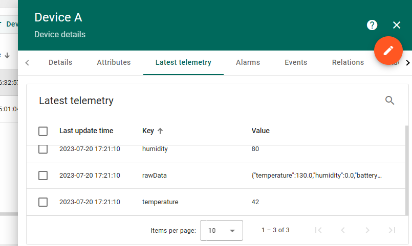
Go to "Device" -> "Search Device", enter the IMEI of the device to find the device.

You can view the data that has just been uplink on the device:

4. MQTT/UDP/TCP downlink
4.1 MQTT (via MQTT.fx)
Configure MQTT connections properly and send downlink commands to configure nodes through the Publish function of MQTT.fx.
1. Configure node MQTT connection (via MQTT.fx):
AT command:
- AT+PRO=3,0 or 3,5 // hex format or json format
- AT+SUBTOPIC=User Defined
- AT+PUBTOPIC=User Defined
- AT+UNAME=<device name> or User Defined
- AT+PWD=<device name> or User Defined
- AT+SERVADDR=8.217.91.207,1883 // to set MQTT server address and port
Note: To uplink and downlink via MQTT.fx, we need set the publish topic and subscribe topic different, for example: AT+SUBTOPIC=SE01_SUB & AT+PUBTOPIC=SE01_PUB.
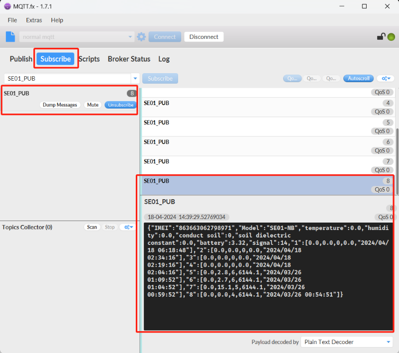
2. When the node uplink packets, we can observe the data in MQTT.fx.
3. The downlink command can be successfully sent only when the downlink port is open.
The downlink port is opened for about 3 seconds after uplink packets are sent.
Therefore, when we see the node uplink packets in the Subscribe window, we need to immediately switch to the publish window to publish the hex format command.
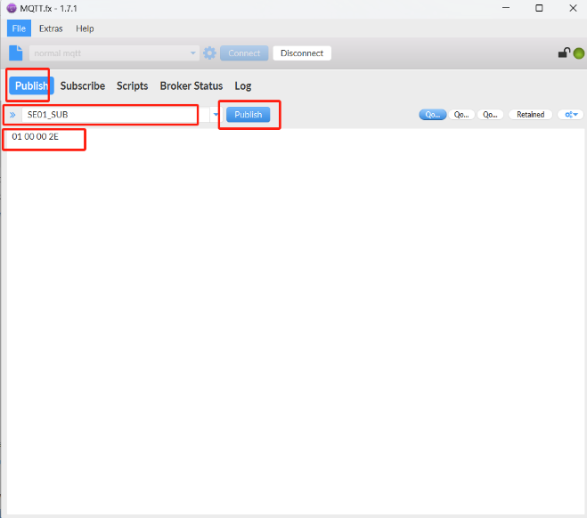
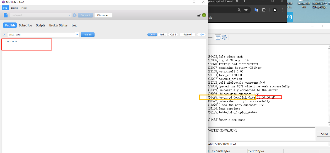
Note: Users can edit the hex command in advance. When the node uplink, directly click the publish button several times to increase the success rate of command configuration.
5. FAQ
5.1 What is the usage of Multi Sampling and One Uplink?
The NB series has the feature for Multi Sampling and one uplink. See one of them
User can use this feature for below purpose:
- Reduce power consumption. The NB-IoT transmit power is much more higher than the sensor sampling power. To save battery life, we can sampling often and send in one uplink.
- Give more sampling data points.
- Increase reliable in transmission. For example. If user set
- AT+TR=1800 // The unit is seconds, and the default is to record data once every 1800 seconds (30 minutes, the minimum can be set to 180 seconds)
- AT+NOUD=24 // The device uploads 24 sets of recorded data by default. Up to 32 sets of record data can be uploaded.
- AT+TDC=7200 // Uplink every 2 hours.
- this will mean each uplink will actually include the 6 uplink data (24 set data which cover 12 hours). So if device doesn't lost 6 continue data. There will not data lost.
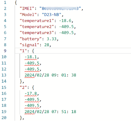
5.2 Why the uplink JSON format is not standard?
The json format in uplink packet is not standard Json format. Below is the example. This is to make the payload as short as possible, due to NB-IoT transmit limition, a standard Json is not able to include 32 sets of sensors data with timestamp.
The firmware version released after 2024, Mar will use change back to use Json format. Detail please check changelog.
5.3 What is the data consumption for different transfer mode?
For the data consumption of NB-IoT End node in different transfer mode, reference link:
https://wiki.dragino.com/xwiki/bin/view/Main/Traffic%20Statistics%20--%20NBCB/
6. Trouble Shooting:
6.1 Checklist for debuging Network Connection issue. Signal Strenght:99 issue.
There are many different providers provide NB-IoT service in the world. They might use different band, different APN & different operator configuration. Which makes connection to NB-IoT network is complicate.
If end device successfully attached NB-IoT Network, User can normally see the signal strengh as below (between 0~31)
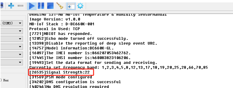
If fail to attach network, it will shows signal 99. as below:
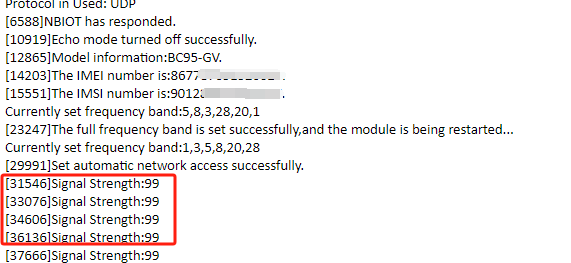
When see this issue, below are the checklist:
- Does your SIM card support NB-IoT network? If SIM card doesn't not specify support NB-IoT clearly, normally it doesn't support. You need to confirm with your operator.
- Do you configure the correct APN? Check here for APN settings.
- Do you lock the frequency band? This is the most case we see. Explain and Instruction.
- Check if the device is attached to Carrier network but reject. (need to check with operator).
- Check if the antenna is connected firmly.
If you have check all above and still fail. please send console log files (as many as possible) to support@dragino.com so we can check.
6.2 Issue: "NBIOT did not respond"
This issue might due to initiate issue for NB-IoT module. In this case, please try:
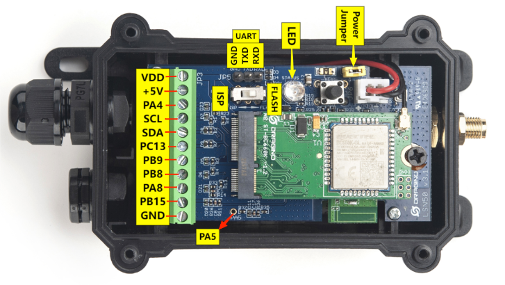
1) Open Enclosure
2) Power off device by pull out the power on Jumper
3) Power on device by connect back the power jumper.
4) push reset button.
6.3 Issue: "Failed to readI MSI number"
Make sure that the SIM card is insert in correct direction and device is power off/on during insert. Here is reference link: Insert SIM Card.
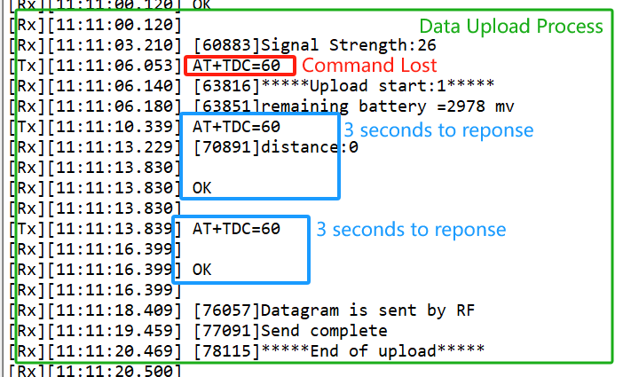
6.4 Why sometime the AT Command is slow in reponse?
When the MCU is communicating with the NB-IoT module, the MCU response of AT Command will become slower, it might takes several seconds to response.
6.5 What is the Downlink Command Format for NB Devices?
Firstly, it is recommended that users upgrade the firmware of the -NB node to the latest version, as the processing method for downlink commands varies depending on the firmware version. Below, we will introduce the latest downlink command format.
UDP Protocol:
Only supports valid HEX-format downlink commands corresponding to AT command.
Take the AT+TDC command of S31-NB as an example, that is, only the valid HEX format downstream command corresponding to the AT+TDC command can be used:
Downward format: 01000384 // There are no Spaces. 0x0384(H)=900(D), that is, modify TDC to 900 seconds.

MQTT Protocol:
1. HEX-format
Supports HEX-format downlink commands (corresponding to AT commands).
Example: For the S31-NB's uplink interval modification (AT+TDC=900):
Downlink command: 01000384 // There are no Spaces. 0x0384(H)=900(D), that is, modify TDC to 900 seconds.

2. JSON-format
2. 1 JSON format template.
All -NB nodes support downlink configuration modification using JSON format templates.
We can use templates to configure multiple commands AT once. Users only need to modify the parameters of the required AT commands in the correct template for each device.
Template.
Take the template of D2x-NB as an example:
{
"AT+SERVADDR":"119.91.62.30,1882",
"AT+CLIENT":"JwcXKjQBNhQ2JykDDAA5Ahs",
"AT+UNAME":"usenamedragino",
"AT+PWD":"passworddragino",
"AT+PUBTOPIC":"123",
"AT+SUBTOPIC":"321",
"AT+TDC":"7200",
"AT+INTMOD":"0",
"AT+APN":"NULL",
"AT+5VT":"0",
"AT+PRO":"3,5",
"AT+TR":"900",
"AT+NOUD":"0",
"AT+CSQTIME":"5",
"AT+DNSTIMER":"0",
"AT+TLSMOD":"0,0",
"AT+MQOS":"0",
"AT+TEMPALARM1":"0",
"AT+TEMPALARM2":"10",
"AT+TEMPALARM3":"0"
}
Explanations of two special commands in the template: AT+TR (set the detection interval: 0 ~ 255 minutes) and AT+NOUD (set the number of groups) correspond to parameters in AT+CLOCKLOG.

Instructions for Using the Template:
- Modify the parameters for each AT command in the template as needed.
- Send the entire template in one downlink command.
Note:
- The template may vary depending on the device model.
- Currently, each specific template is being updated and tested. If you need a template for your specific device, please contact Dragino Technical Support at support@dragino.com to request the latest downlink template.
2.2 Support sending json format commands separately
Some models of nodes support sending json format commands separately:RS485-NB, LDS25-NB, CS01-NB, SDI-12-NB, SW3L-NB, WL03A-NB, PS-NB, LTC2-NB.
Example: For the PS-NB's uplink interval modification (AT+TDC=900):
Downlink command: {AT+TDC=900} // The correct format is {AT Command}. No extra characters other than valid AT commands can be added within {}.
Note:
1. Only when the correct and valid download command is used and the format is correct can the device be configured through the download command. Invalid download content cannot be processed by the device and will be automatically restarted.
2. Devices designed with downlink commands can utilize different downlink formats (e.g., JSON or HEX) for configuration. However, regardless of the format, the functionality is strictly limited to the downlink command specifications described in the user manual's AT command explanation.
For example, the HEX-format downlink command corresponding to AT+TDC can only be used to configure TDC and cannot be used for queries. There is no HEX-format downlink command equivalent to AT+TDC=? , so querying TDC via downlink is not supported.
6.6 How to get the debug log for further analyze?
If user is not able to solve the connection issue, user can use below method and get the device log and send to Dragino (Support@dragino.cc) for further analyze.
Step1: Use Mobile Phone to connect device
See this link: how to connect via Mobile Phone:
Step2: Get Log by different commands.
Use below three method to generate logs.
- AT+CFG --> Command to show the current configuration
- AT +GETLOG --> Command to get the previous upstream log
- press the toggle button for 1 ~2 seconds --> Trigger a uplink
Above are the output example for about three action:

Step3: Export Log

select the log you want to export, then click the share icon on the far right to enter the document that comes with your phone and choose to export it.

6.7 How to find the AT Command Password if lost?
Why can't the password access AT command after upgrade(-NB)?
Because the new version of -NB firmware has updated the factory reset function, users can choose to restore all parameters to factory Settings, or keep the password to restore the rest of the parameters to factory Settings.
This update changes the password address of the firmware, so the password will be invalid after the customer upgrades from the old version of firmware (without FDR1 function) to the new version of firmware (with FDR1 function).
Two different restore factory Settings configurations.
AT command:
- AT+FDR // Reset Parameters to Factory Default.
- AT+FDR1 // Reset parameters to factory default values except for passwords.(new)
Version Confirmation
We are now dividing the old firmware(without FDR1 function) with the new firmware(with FDR1 function) by whether it contains FDR1 functionality. Please refer to the table:
| General Model | Firmware version (without FDR1 function) | Firmware version (with FDR1 function) |
CPL03-NB, S31-NB, SN50V3-NB, TS01-NB, D20-NB, DS03A-NB, DDS04-NB, DDS45-NB, DDS20-NB, DDS75-NB, LDS12-NB, LDS40-NB, LMS01-NB, MDS120-NB, MDS200-NB, SE01-NB, SPH01-NB; | Before V1.2.1 | After V1.2.1 (including V1.2.1) |
WL03A-NB, SDI-12-NB; | Before V1.0.2 | After V1.0.8 (including V1.0.2) |
SW3L-NB, PS-NB; | Before V1.0.5 | After V1.0.5 (including V1.0.5) |
| RS485-NB | Before V1.0.8 | After V1.0.8 (including V1.0.8) |
UART connection and firmware update methods
Users can query passwords only using the UART interface via the STM32CubeProgrammer.
See UART Connection.
update firmware through UART TTL interface : Instruction.
query the password via STM32CubeProgrammer
Users can use the password address to query the password through STM32CubeProgrammer.
- The password address for old firmware(without FDR1 function) : 0x08019000
- The password address for new firmware(with FDR1 function) : 0x08025D00
Notice: The password can only be queried after the firmware is run once.
Procedure for querying the password(old firmware):
- After the firmware upgrade is complete, switch back to the FLASH and reset the node to run the firmware once.
- Then place the switch at the ISP and connect to the STM32CubeProgrammer (same as when burning the firmware).
- Click "Device memory", enter 0x08019000 in "Address", and click "Read"
- Find the 0x08019000 address field and then read the current password as shown in the screenshot below.

Procedure for querying the password(new firmware):
Refer to the old and new firmware division above, and run the firmware first after updating the firmware.
- After the firmware upgrade is complete, switch back to the FLASH and reset the node to run the new firmware once.
- Then place the switch at the ISP and connect to the STM32CubeProgrammer (same as when burning the firmware).
- Click "Device memory", enter 0x08025D00 in "Address", and click "Read"
- Find the 0x08025D00 address field and then read the current password as shown in the screenshot below.

Special case
If the user has never changed the password manually, the user cannot find the valid password through the above two password addresses. In this case, the valid password is still the original password on the node box label (AT+PIN).
Invalid query screenshot example:


6.8