UART Access for NB ST-BC660K-GL base model (for AT Commands, firmware upgrade)
Table of Contents:
- 1. NB ST-BC660K-GL base Hardware
- 2. Hardware Wiring for UART
- 3. UART for AT Commands
- 4. Firmware Upgrade
- 5. FAQ
1. NB ST-BC660K-GL base Hardware
Below hardware use NB ST -BC660K-GL module. They support UART Access for AT Command and Firmware Upgrade.
| Models | Mother Board | UART Wiring | UART for Upgrade Firmware |
|---|---|---|---|
| PS-NB, PS-NB-NA, SDI12-NB | SIB | Instruction | Instruction |
SN50v3-NB, S31-NB, S31B-NB, D20-NB. D20S-NB, D21-NB, D22-NB, DS03A-NB, | SN50v3 | Instruction | Instruction |
RS485-NB, SE01-NB, SPH01-NB, LMS01-NB, LDS12-NB, LDS40-NB, DDS75-NB, DDS45-NB, DDS04-NB, DDS20-NB, MDS120-NB, MDS200-NB, WSC2-NB | RS485-BL | Instruction | Instruction |
2. Hardware Wiring for UART
Connection Structure:
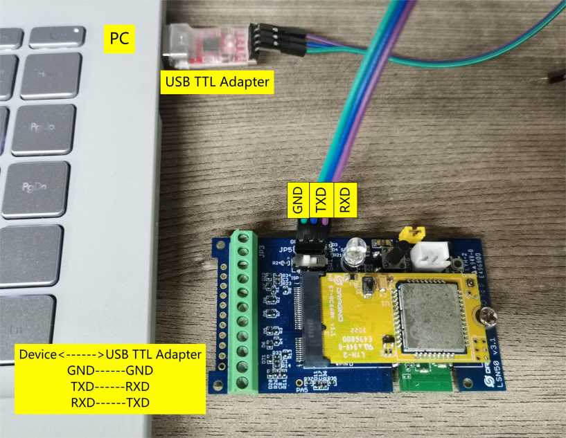
2.1 SN50v3 base mother board
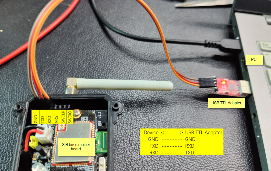
2.2 SIB mother board
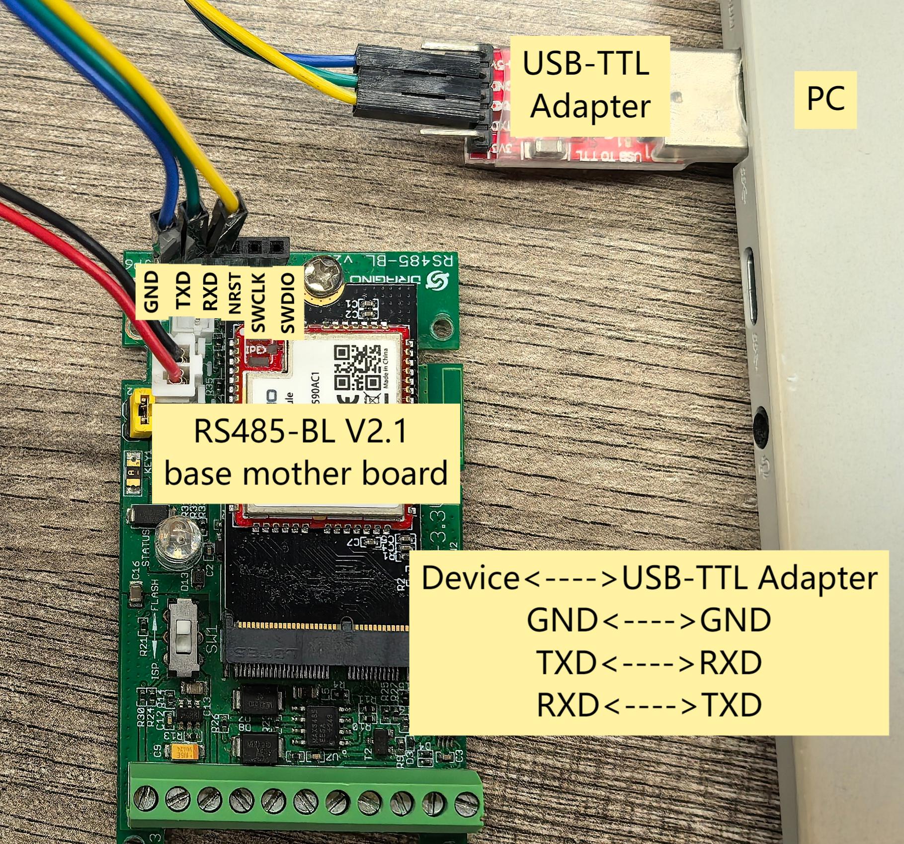
2.3 UART Connection for RS485-BL V2.1 base mother board
3. UART for AT Commands
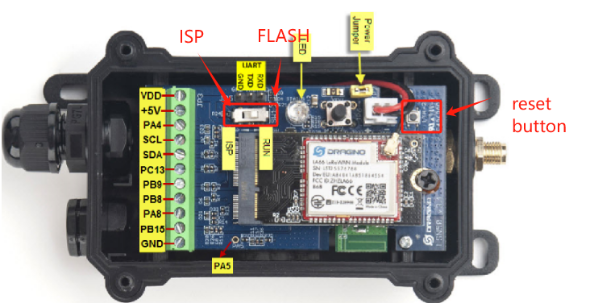
Step1: Connect UART Interface & Set to Flash Mode
Step2: Use Serial Utility to connect
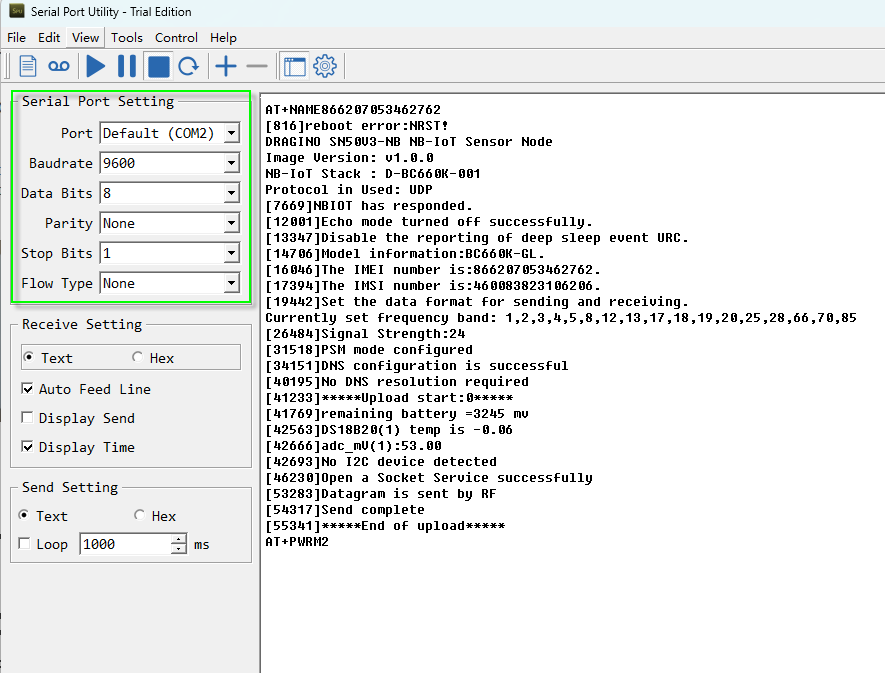
- 1. Use a general serial tool. Download Serial Port Utility
- 2. Set up serial tool with : BaudRate: 9600, databit:8, No parity, No flow control.
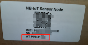
- 3. The AT Command Password is printed as AT PIN in the sticker on the giftbox.
Example:
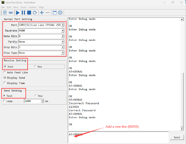
Notice: When Input AT Command. Please add a new line:
4. Firmware Upgrade
4.1 Check Your device already has bootloader
4.1.1 Firmware Structure
The -NB/-NS firmware structure is as below:
4.1.2 What is Dragino Bootloader for NB-IoT Model?
Dragino NB Bootloader is a bootloader which support below features:
- OTA Update via BLE
- OTA Batch update configure via BLE (Not Finished)
All Dragino End Devices which support BLE module are shipped with the NB Bootloader.
4.1.3 How can i know if my device already have bootloader?
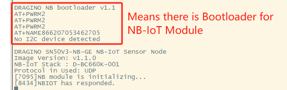
If a device has a bootloader. it will output bootloader info to UART when boot. As below:
4.1.4 How to upload bootloader to device?
If your is NB ST -BC660K-GL base hardware but doesn't have bootloader or The bootloader is erased by mistake. You can upload a bootloader to it. ( This instruction works no matter the device has bootloader or not)
Downlink Link for NB-IoT BLE bootloader.
Step1: download STM32 Cubeprogramer
Step2: Connect wires to Device's UART interface & Set Device to ISP mode
See UART Connection method for each device.
Step3: Use STM32 Cube to Connect Device
Note: Before clicking the "Connect", users need to press the reset button to reset the node, otherwise the connection may be incorrect, for example:

Successful connection:

Step4: Choose NB Bootloader and Start Programming


Step5: Verify Programming

Step6: Switch Jumper from ISP to Flash mode
4.2 Update Firmware (Assume the device already have a bootloader)
Step1: Download STM32 Cubeprogramer
Step2: Connect wires to Device's UART interface & Set Device to ISP mode
See UART Connection method for each device.
Step3: Use STM32 Cube to Connect Device
Note: Before clicking the "Connect", users need to press the reset button to reset the node, otherwise the connection may be incorrect, for example:

Successful connection:

Step4: Choose NB firmware and Start Programming
NB Firmware download address: NB-IoT - Dropbox. .hex &.binfiles can be burned directly.


Step5: Verify Programming

Step6: Switch Jumper from ISP to Flash mode
5. FAQ
5.1 What is the difference between .hex and .bin file?
When compile the firmware, there will be two files .hex and .bin. they are different:
- .bin : original firmware file. When use .bin file and update in STM32Cube, you need to specify the start address.
- .hex : file with control / meta info. When use .hex file and update in STM32Cube, you don't need to specify the start address. They are included in the file so hex file is bigger in size but actually firmware are the same.
Example:
- For the .hex firmware, the STM32CubeProgrammer will automatically recognize the burning address as 0x8007800.

- For the.bin firmware, STM32CubeProgrammer will automatically identify the burning address as 0x08000000.

- In addition, our boot loader should use the burning address 0x08000000. When burning the boot loader, the STM32CubeProgrammer will also automatically recognize the burning address as 0x08000000.

Therefore, when using the.bin firmware, users should manually configure the burning address to 0x8007800.
Otherwise, the working firmware will overwrite the boot loader, and the node will be unusable (the LED indicator light will not respond, and there will be no content when viewing the node startup information).
For the opened firmware file, modify the address at the place shown in the screenshot below:

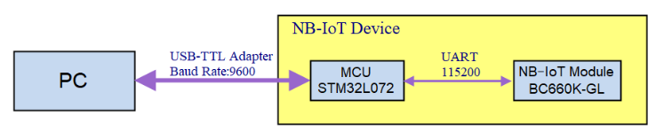
5.2 How to use PC to send UART command to NB-IoT Module directly?
The default UART Connection as per above instruction is as below. PC is communicating with the MCU instead of NB-IoT Module.
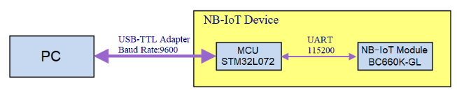
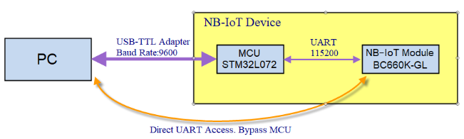
User can use MCU to pass AT Commands to NB-IoT modules. But in some case, we want the PC to communicate with NB-IoT module directly for advance debugging.
Structure like below:
To do above, below are the step:
- Upload a none-working firmware in the MCU STM32L072. So the STM32L072 will not send any AT Command to NB-IoT module to avoid conflict when you use PC to communicate with NB-Iot Module.
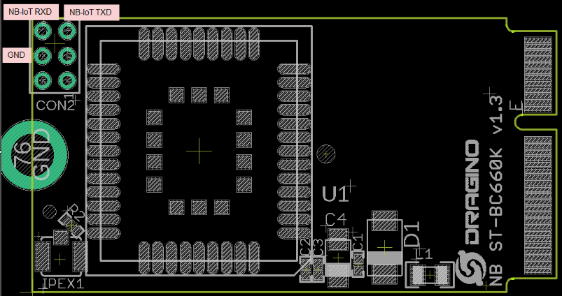
- Connect PC to the TXD/RXD/GND pins of NB-IoT module BC660K-GL directly via USB to TTL adapter. Below is the location for the pins:
Reference: BC660K-GL Module AT Commands & Software Document.