PS-NB-NA -- NB-IoT Analog Sensor User Manual
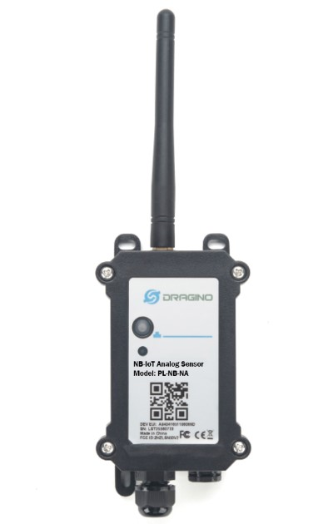
Table of Contents:
- 1. Introduction
- 2. Use PS-NB-NA to communicate with IoT Server
- 2.1 Send data to IoT server via NB-IoT network
- 2.2 Payload Types
- 2.3 Test Uplink and Change Update Interval
- 2.4 Multi-Samplings and One uplink(It is replaced by AT+CLOCKLOG)
- 2.5 Trggier an uplink by external interrupt
- 2.6 Set Power Output Duration
- 2.7 Set the Probe Model
- 2.8 Clock logging (Since firmware version v1.0.5)
- 2.9 Example Query saved historical records
- 2.10 Uplink log query
- 2.11 Scheduled domain name resolution
- 2.12 Set the QoS level
- 2.13 Set the downlink debugging mode(Since firmware v1.2.0)
- 2.14 Domain name resolution settings(Since firmware v1.2.0)
- 2.15 Print last few data entries
- 2.16 Print data entries base on page
- 2.17 Clear Flash Record
- 2.18 Set CoAP option
- 2.19 Set device auto-reset time (Since firmware v1.2.4)
- 2.20 Set failure-triggered reset (Since firmware v1.2.4)
- 3. Configure PS-NB-NA
- 4. Battery & Power Consumption
- 5. Firmware update
- 6. FAQ
- 7. Order Info
- 8. Packing Info
- 9. Support
1. Introduction
1.1 What is NB-IoT Analog Sensor
The Dragino PS-NB-NA is a NB-IoT Analog Sensor for Internet of Things solution. PS-NB-NA has 5v and 12v output, 4~20mA, 0~30v input interface to power and get value from Analog Sensor. PS-NB-NA will convert the Analog Value to NB-IoT wireless data and send to IoT platform via NB-IoT network.
PS-NB-NA supports different uplink methods including MQTT, MQTTs, UDP ,TCP&CoAP for different application requirement, and support uplinks to various IoT Servers.
PS-NB-NA supports BLE configure and OTA update which make user easy to use.
PS-NB-NA is powered by 8500mAh Li-SOCI2 battery, it is designed for long-term use up to several years.
PS-NB-NA has optional built-in SIM card and default IoT server connection version. Which makes it works with simple configuration.
1.2 Features
- NB-IoT Bands: B1/B2/B3/B4/B5/B8/B12/B13/B17/B18/B19/B20/B25/B28/B66/B70/B85 @H-FDD
- Ultra-low power consumption
- 1 x 0~20mA input , 1 x 0~30v input
- 5v and 12v output to power external sensor
- Multiply Sampling and one uplink
- Support Bluetooth v5.1 remote configure and update firmware
- Uplink on periodically
- Downlink to change configure
- 8500mAh Battery for long term use
- IP66 Waterproof Enclosure
- Uplink via MQTT, MQTTs, TCP, or UDP
- Nano SIM card slot for NB-IoT SIM
1.3 Specification
Common DC Characteristics:
- Supply Voltage: 2.5v ~ 3.6v
- Operating Temperature: -40 ~ 85°C
Current Input (DC) Measuring :
- Range: 0 ~ 20mA
- Accuracy: 0.02mA
- Resolution: 0.001mA
Voltage Input Measuring:
- Range: 0 ~ 30v
- Accuracy: 0.02v
- Resolution: 0.001v
NB-IoT Spec:
NB-IoT Module: BC660K-GL
Support Bands:
- B1 @H-FDD: 2100MHz
- B2 @H-FDD: 1900MHz
- B3 @H-FDD: 1800MHz
- B4 @H-FDD: 2100MHz
- B5 @H-FDD: 860MHz
- B8 @H-FDD: 900MHz
- B12 @H-FDD: 720MHz
- B13 @H-FDD: 740MHz
- B17 @H-FDD: 730MHz
- B18 @H-FDD: 870MHz
- B19 @H-FDD: 870MHz
- B20 @H-FDD: 790MHz
- B25 @H-FDD: 1900MHz
- B28 @H-FDD: 750MHz
- B66 @H-FDD: 2000MHz
- B70 @H-FDD: 2000MHz
- B85 @H-FDD: 700MHz
Battery:
- Li/SOCI2 un-chargeable battery
- Capacity: 8500mAh
- Self Discharge: <1% / Year @ 25°C
- Max continuously current: 130mA
- Max boost current: 2A, 1 second
Power Consumption
- STOP Mode: 10uA @ 3.3v
- Max transmit power: 350mA@3.3v
1.4 Applications
- Smart Buildings & Home Automation
- Logistics and Supply Chain Management
- Smart Metering
- Smart Agriculture
- Smart Cities
- Smart Factory
1.5 Sleep mode and working mode
Deep Sleep Mode: Sensor doesn't have any NB-IoT activate. This mode is used for storage and shipping to save battery life.
Working Mode: In this mode, Sensor will work as NB-IoT Sensor to Join NB-IoT network and send out sensor data to server. Between each sampling/tx/rx periodically, sensor will be in IDLE mode), in IDLE mode, sensor has the same power consumption as Deep Sleep mode.
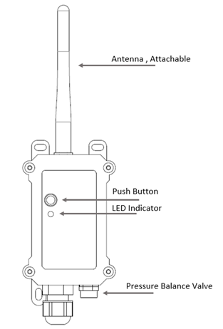
1.6 Button & LEDs
| Behavior on ACT | Function | Action |
|---|---|---|
 1~3s 1~3s | Send an uplink | If sensor has already attached to NB-IoT network, sensor will send an uplink packet, blue led will blink once. |
 >3s >3s | Active Device | Green led will fast blink 5 times, device will enter OTA mode for 3 seconds. And then start to attach NB-IoT network. |
 x5 x5 | Deactivate Device | Red led will solid on for 5 seconds. Means device is in Deep Sleep Mode. |
Note: When the device is executing a program, the buttons may become invalid. It is best to press the buttons after the device has completed the program execution.
1.7 BLE connection
PS-NB-NA support BLE remote configure and firmware update.
BLE can be used to configure the parameter of sensor or see the console output from sensor. BLE will be only activate on below case:
- Press button to send an uplink
- Press button to active device.
- Device Power on or reset.
If there is no activity connection on BLE in 60 seconds, sensor will shut down BLE module to enter low power mode.
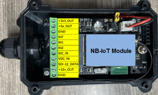
1.8 Pin Definitions , Switch & SIM Direction
PS-NB-NA use the mother board which as below.
1.8.1 Jumper JP2
Power on Device when put this jumper.
1.8.2 BOOT MODE / SW1
1) ISP: upgrade mode, device won't have any signal in this mode. but ready for upgrade firmware. LED won't work. Firmware won't run.
2) Flash: work mode, device starts to work and send out console output for further debug
1.8.3 Reset Button
Press to reboot the device.
1.8.4 SIM Card Direction
See this link. How to insert SIM Card.
1.9 Mechanical

2. Use PS-NB-NA to communicate with IoT Server
2.1 Send data to IoT server via NB-IoT network
The PS-NB-NA is equipped with a NB-IoT module, the pre-loaded firmware in PS-NB-NA will get environment data from sensors and send the value to local NB-IoT network via the NB-IoT module. The NB-IoT network will forward this value to IoT server via the protocol defined by PS-NB-NA.
Below shows the network structure:

There are two version: -GE and -1T version of PS-NB-NA.
GE Version: This version doesn't include SIM card or point to any IoT server. User needs to use AT Commands to configure below two steps to set PS-NB-NA send data to IoT server.
- Install NB-IoT SIM card and configure APN. See instruction of Attach Network.
- Set up sensor to point to IoT Server. See instruction of Configure to Connect Different Servers.
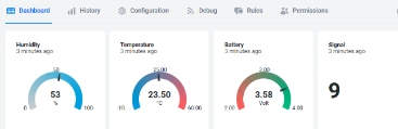
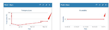
Below shows result of different server as a glance.
| Servers | Dash Board | Comments |
| Node-Red |
| |
| DataCake |
| |
| Tago.IO | ||
| General UDP | Raw Payload. Need Developer to design Dash Board | |
| General MQTT | Raw Payload. Need Developer to design Dash Board | |
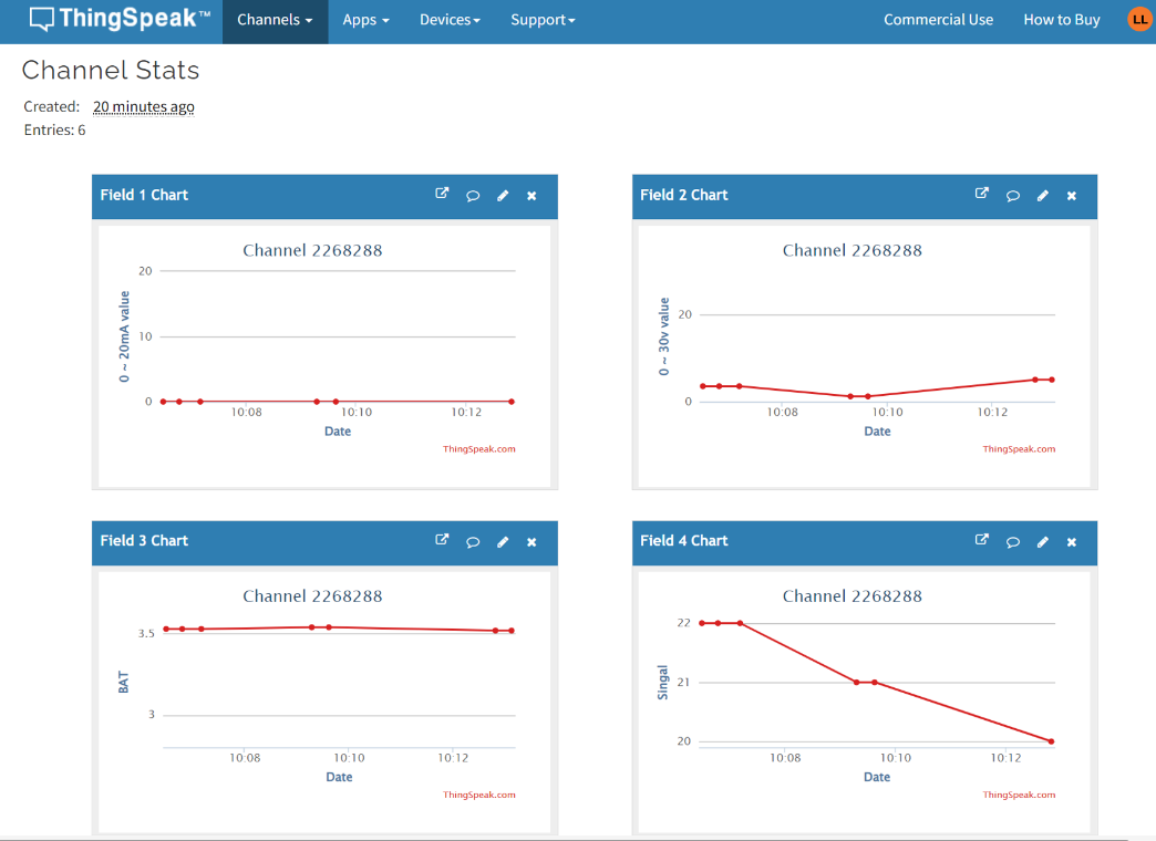
| ThingSpeak |
| |
| ThingsBoard |
|
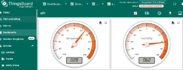
1T Version: This version has 1NCE SIM card pre-installed and configure to send value to ThingsEye. User Just need to select the sensor type in ThingsEyeand Activate PS-NB-NA and user will be able to see data in ThingsEye. See here for ThingsEye Config Instruction.
2.2 Payload Types
To meet different server requirement, PS-NB-NA supports different payload type.
Includes:
- General JSON format payload. (Type=5)
- HEX format Payload. (Type=0)
- ThingSpeak Format. (Type=1)
- ThingsBoard Format. (Type=3)
User can specify the payload type when choose the connection protocol. Example:
AT+PRO=1,0 // Use Coap Connection & hex Payload
AT+PRO=1,5 // Use Coap Connection & Json Payload
AT+PRO=2,0 // Use UDP Connection & hex Payload
AT+PRO=2,5 // Use UDP Connection & Json Payload
AT+PRO=3,0 // Use MQTT Connection & hex Payload
AT+PRO=3,1 // Use MQTT Connection & ThingSpeak
AT+PRO=3,3 // Use MQTT Connection & ThingsBoard
AT+PRO=3,5 // Use MQTT Connection & Json Payload
AT+PRO=4,0 // Use TCP Connection & hex Payload
AT+PRO=4,5 // Use TCP Connection & Json Payload
2.2.1 General Json Format(Type=5)
This is the General Json Format. As below:
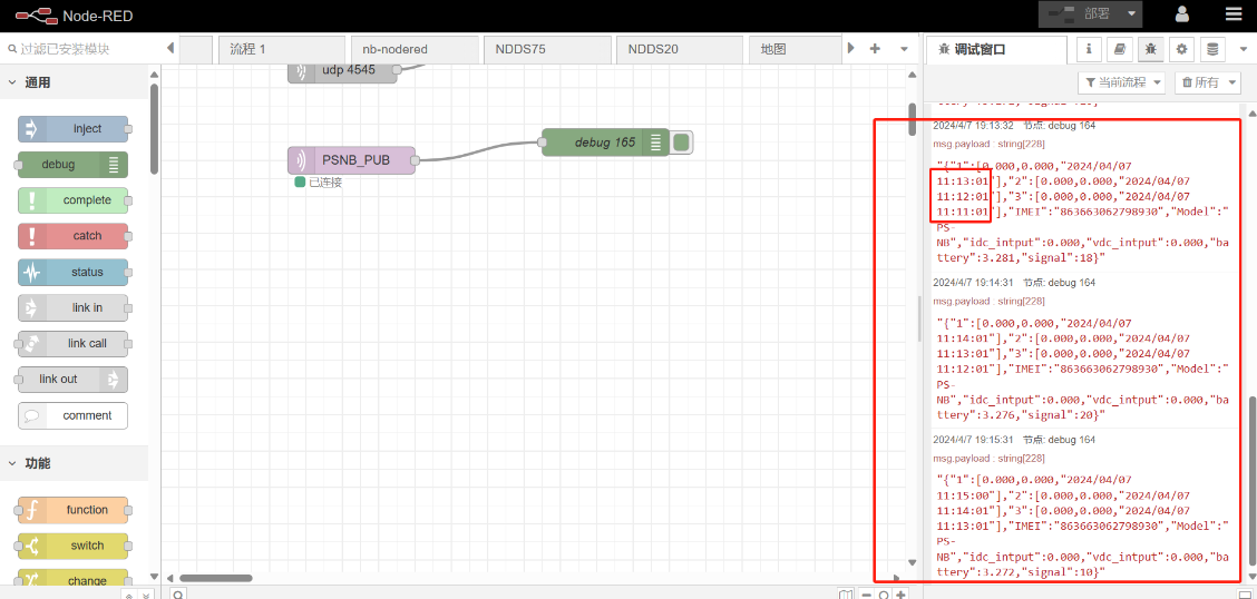
{"IMEI":"863663062798815","IMSI":"460083513507309","Model":"PS-NB","idc_intput":0.000,"vdc_intput":9.934,"battery":3.587,"signal":25,"time":"2024/12/20 02:51:05","1":[0.000,0.000,"2024/12/18 01:14:56"],"2":[0.000,0.000,"2024/12/18 00:59:56"],"3":[0.000,0.000,"2024/12/18 00:44:56"],"4":[0.000,0.000,"2024/12/18 00:29:56"],"5":[0.000,0.000,"2024/12/18 00:14:56"],"6":[0.000,0.000,"2024/12/17 23:59:56"],"7":[0.000,0.000,"2024/12/17 23:44:56"],"8":[0.000,0.000,"2024/12/17 23:29:56"]}

Notice, from above payload:
- Idc_input , Vdc_input , Battery, Signal & time are the value at uplink time.
- Json entry 1 ~ 8 are the last 1 ~ 8 sampling data as specify by AT+CLOCKLOG=1,65535,15,8 Command. Each entry includes (from left to right): Idc_input , Vdc_input, Sampling time.
2.2.2 HEX format Payload(Type=0)
This is the HEX Format. As below:
f863663062798815f46008351350730901790e0317000000000000000026d06764dcab00000000676222100000000067621e8c0000000067621b0800000000676217840000000067621400000000006762107c0000000067620cf80000000067620974


Device ID(f+IMEI): f863663062798815 =863663062798815
SIM Card ID(f+IMSI): f460083513507309 =460083513507309
Version:
These bytes include the hardware and software version.
Higher byte: Specify Sensor Model: 0x01 for PS-NB-NA
Lower byte: Specify the software version: 0x79=1.2.1, means firmware version 1.2.1
BAT (Battery Info):
Check the battery voltage for PS-NB-NA.
Ex1: 0x0dde = 3550mV
Ex2: 0x0B49 = 2889mV
Signal Strength:
NB-IoT Network signal Strength.
Ex1: 0x13 = 19
0 -113dBm or less
1 -111dBm
2...30 -109dBm... -53dBm
31 -51dBm or greater
99 Not known or not detectable
Probe Model:
PS-NB-NA might connect to different kind of probes, 4~20mA represent the full scale of the measuring range. So a 12mA output means different meaning for different probe.
For example.
| Probe Type | 4~20mA scale for this probe | Example: 12mA actually meaning for this probe |
| PH Combination Electrodes | 0 ~ 14 pH | PH Value: 7 |
| Water Pressure Sensor | 0~5 meters | 2.5 meters pure water |
| Pressure transmitter probe | 0~1MPa | 0.5MPa air / gas or water pressure |
User can set different probe model for above probes. So IoT server is able to se identical how it should parse the 4~20mA or 0~30v sensor value and get the correct value.
IN1 & IN2:
IN1 and IN2 are used as Digital input pins.
Example:
01 (H): IN1 or IN2 pin is high level.
00 (L): IN1 or IN2 pin is low level.
GPIO_EXTI Level:
GPIO_EXTI is used as Interrupt Pin.
Example:
01 (H): GPIO_EXTI pin is high level.
00 (L): GPIO_EXTI pin is low level.
GPIO_EXTI Flag:
This data field shows if this packet is generated by Interrupt Pin or not.
Note: The Interrupt Pin is a separate pin in the screw terminal.
Example:
0x00: Normal uplink packet.
0x01: Interrupt Uplink Packet.
0~20mA:
Example:
27AE(H) = 10158 (D)/1000 = 10.158mA.
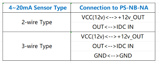
Connect to a 2 wire 4~20mA sensor.

0~30V:
Measure the voltage value. The range is 0 to 30V.
Example:
138E(H) = 5006(D)/1000= 5.006V
TimeStamp:
Unit TimeStamp Example: 64e2d74f(H) = 1692587855(D)
Put the decimal value into this link(https://www.epochconverter.com))to get the time.
2.2.3 ThingsBoard Payload(Type=3)
Type3 payload special design for ThingsBoard, it will also configure other default server to ThingsBoard.
{
"topic": "004_NB",
"payload": {
"IMEI": "863663062798815",
"IMSI": "460083513507309",
"Model": "PS-NB",
"idc_intput": 0.0,
"vdc_intput": 0.0,
"battery": 3.584,
"signal": 23,
"time": "2024/12/17 03:37:25",
"1": [0.273, 0.443, "2024/08/26 09:40:35"],
"2": [0.275, 0.442, "2024/08/26 07:39:55"],
"3": [0.281, 0.554, "2024/08/23 09:49:04"],
"4": [0.276, 0.554, "2024/08/23 09:13:40"],
"5": [0.256, 0.0, "2024/08/23 08:58:40"],
"6": [0.0, 0.003, "2024/08/23 08:43:40"],
"7": [0.278, 0.528, "2024/08/23 08:28:40"],
"8": [1.3, 0.0, "2024/08/23 07:48:31"]
}
}

2.2.4 ThingSpeak Payload(Type=1)
This payload meets ThingSpeak platform requirement. It includes only four fields. Form 1~4 are:
Idc_input , Vdc_input , Battery & Signal. This payload type only valid for ThingsSpeak Platform
As below:
field1=idc_intput value&field2=vdc_intput value&field3=battery value&field4=signal value
2.3 Test Uplink and Change Update Interval
By default, Sensor will send uplinks every 2 hours
User can use below commands to change the uplink interval.
AT Command: AT+TDC
Example: AT+TDC=7200 // Set Update Interval to 7200 seconds
Downlink Command: 0x01
Format: Command Code (0x01) followed by 3 bytes.
Example: 12 hours= 43200 seconds 43200(D)=0xA8C0(H)
Downlink Payload: 01 00 A8 C0 // AT+TDC=43200, Set Update Interval to 12 hours.
Note: User can also push the button for more than 1 second to activate an uplink.
2.4 Multi-Samplings and One uplink(It is replaced by AT+CLOCKLOG)
Notice: The AT+NOUD feature is upgraded to Clock Logging, please refer Clock Logging Feature.
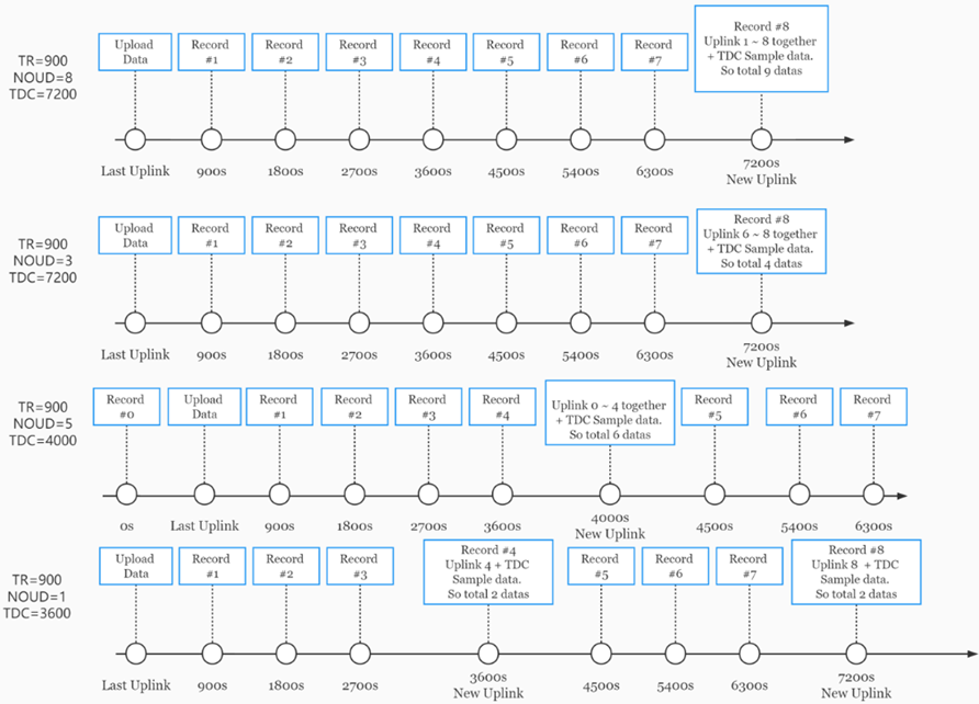
To save battery life, PS-NB-NA will sample Idc_input & Vdc_input data every 15 minutes and send one uplink every 2 hours. So each uplink it will include 8 stored data + 1 real-time data. They are defined by:
- AT+TR=900 // The unit is seconds, and the default is to record data once every 900 seconds (15 minutes, the minimum can be set to 180 seconds)
- AT+NOUD=8 // The device uploads 8 sets of recorded data by default. Up to 32 sets of record data can be uploaded.
The diagram below explains the relationship between TR, NOUD, and TDC more clearly:
2.5 Trggier an uplink by external interrupt
PS-NB-NA has an external trigger interrupt function. Users can use the GPIO_EXTI pin to trigger the upload of data packets.
AT command:
- AT+INTMOD // Set the trigger interrupt mode
- AT+INTMOD=0 // Disable Interrupt,as a digital input pin
- AT+INTMOD=1 // Trigger by rising and falling edge
- AT+INTMOD=2 // Trigger by falling edge
- AT+INTMOD=3 // Trigger by rising edge
2.6 Set Power Output Duration
Control the output duration 3V3 , 5V or 12V. Before each sampling, device will
1. first enable the power output to external sensor,
2. keep it on as per duration, read sensor value and construct uplink payload
3. final, close the power output.
- Set extend the time of 3V3 power:
AT Command: AT+3V3T
| Command Example | Function | Response |
|---|---|---|
| AT+3V3T=? | Show 3V3 open time. | 0 |
| AT+3V3T=0 | Normally open 3V3 power supply. | OK |
| AT+3V3T=1000 | Close after a delay of 1000 milliseconds. | OK |
| AT+3V3T=65535 | Normally closed 3V3 power supply. | OK |
Downlink Command: 0x0701
Example 1: Downlink Payload: 070101F4 ---> AT+3V3T=500
Example 2: Downlink Payload: 0701FFFF ---> AT+3V3T=65535
- Set extend the time of 5V power:
AT Command: AT+5VT
| Command Example | Function | Response |
|---|---|---|
| AT+5VT=? | Show 5V open time. | 0 |
| AT+5VT=0 | Normally closed 5V power supply. | OK |
| AT+5VT=1000 | Close after a delay of 1000 milliseconds. | OK |
| AT+5VT=65535 | Normally open 5V power supply. | OK |
Downlink Command: 0x0702
Example 3: Downlink Payload: 070203E8 ---> AT+5VT=1000
Example 4: Downlink Payload: 07020000 ---> AT+5VT=0
- Set extend the time of 12V power:
AT Command: AT+12VT
| Command Example | Function | Response |
|---|---|---|
| AT+12VT=? | Show 12V open time. | 0 |
| AT+12VT=0 | Normally closed 12V power supply. | OK |
| AT+12VT=500 | Close after a delay of 500 milliseconds. | OK |
| AT+12VT=65535 | Normally open 5V power supply. | OK |
Downlink Command: 0x0703
Example 5: Downlink Payload: 070301F4 ---> AT+12VT=500
Example 6: Downlink Payload: 07030000 ---> AT+12VT=0
2.7 Set the Probe Model
Users need to configure this parameter according to the type of external probe. In this way, the server can decode according to this value, and convert the current value output by the sensor into water depth or pressure value.
AT Command: AT +PROBE
AT+PROBE=aabb
When aa=00, it is the water depth mode, and the current is converted into the water depth value; bb is the probe at a depth of several meters.
When aa=01, it is the pressure mode, which converts the current into a pressure value;
bb represents which type of pressure sensor it is.
| Command Example | Function | Response |
| AT +PROBE =? | Get or Set the probe model. | 0 OK |
| AT +PROBE =0003 | Set water depth sensor mode, 3m type. | OK |
AT +PROBE =000A
| Set water depth sensor mode, 10m type. | OK |
| AT +PROBE =0101 | Set pressure transmitters mode, first type. | OK |
| AT +PROBE =0000 | Initial state, no settings. | OK |
- Downlink command: 0x0A
Format: Command Code (0x08) followed by 2 bytes.
- Example 1: Downlink Payload: 080003 ---> AT+PROBE=0003
- Example 2: Downlink Payload: 080101 ---> AT+PROBE=0101
Note: When entering the downlink payload, there must be no Spaces between bytes.
2.8 Clock logging (Since firmware version v1.0.5)
Sometimes when we deploy lots of end nodes in field. We want all sensors sample data at the same time, and upload these data together for analyze. In such case, we can use clock loging feature.
We can use this command to set the start time of data recording and the time interval to meet the requirements of the specific collection time of data.
- AT Command: AT +CLOCKLOG=a,b,c,d
a: 0: Disable Clock logging. 1: Enable Clock Logging
b: Specify First sampling start second: range (0 ~ 3599, 65535) // Note: If parameter b is set to 65535, the log period starts after the node accesses the network and sends packets.
c: Specify the sampling interval: range (0 ~ 255 minutes)
d: How many entries should be uplink on every TDC (max 32)
Note: To disable clock recording, set the following parameters: AT+CLOCKLOG=1,65535,0,0
Example:
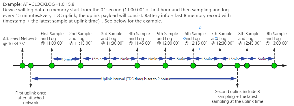
AT+CLOCKLOG=1,65535,1,3
After the node sends the first packet, data is recorded to the memory at intervals of 1 minute. For each TDC uplink, the uplink load will include: battery information + the last 3 memory records (payload + timestamp).
Note: Users need to synchronize the server time before configuring this command. If the server time is not synchronized before this command is configured, the command takes effect only after the node is reset.
- Downlink command: 0x0A
Format: Command Code (0x03) followed by 5 bytes.
- Example 1: Downlink Payload: 0301FFFF0F08 // Set SHT record time: AT+CLOCKLOG=1,65535,15,8
- Example 1: Downlink Payload: 030104B00F08 // Set SHT record time: AT+CLOCKLOG=1,1200,15,8
Note: When entering the downlink payload, there must be no Spaces between bytes.
Unix TimeStamp
PS-NB uses Unix TimeStamp format based on

User can get this time from link: https://www.epochconverter.com/ :
Below is the converter example

So, 1735012365 means that the current time is Tuesday, December 24, 2024 at 11:52 AM.
Poll sensor value
User can poll sensor value based on timestamps from the server. Below is the downlink command.
| 1 byte | 4 bytes | 4 bytes |
|---|---|---|
| 31 | Timestamp start | Timestamp end |
Timestamp start and Timestamp end use Unix TimeStamp format as mentioned above. Devices will reply with all data log during this time period.
For example, downlink command 31 676A 300D 676A 48A9
Is to check 2024/12/24 03:52:45 to 2024/12/24 05:37:45's data
Datalog Uplink payload
The Datalog poll reply uplink will use below payload format.
Retrieval data payload:
| Size(bytes) | 2 | 2 | 4 |
|---|---|---|---|
| value | 0~20mA | 0~30V | Timestamp |
Function Description: This feature is only used when the clock logging feature is turned on. one uplink packet can send 64 groups of stored data totaling 512 bytes.
Example(For MQTT.fx):
If user sends below downlink command:
Where : Start time: 676A300D = time 24/12/24 03:52:45
Stop time: 676A48A9 = time 24/12/24 05:37:45
PS-NB will uplink this payload.

0x00003caf676a300d 0000795d676a3391 00003caf676a3715 0000795d676a3a99 00003caf676a3e1d 00003caf676a41a1 00003caf676a4525 00003caf676a48a9

0~20mA = 0x0000/1000 = 0 mA
0~30V = 0x3caf/1000 = 15.535 V
Unix time is 0x676A300D = 1735012365s = 24/12/24 03:52:45
2.9 Example Query saved historical records
- AT command: AT+CDP
This command can be used to search the saved history, recording up to 32 groups of data, each group of historical data contains a maximum of 100 bytes.

2.10 Uplink log query
- AT command: AT+GETLOG
This command can be used to query upstream logs of data packets.

2.11 Scheduled domain name resolution
This command is used to set up scheduled domain name resolution.
AT command:
- AT+DNSTIMER // Unit: hour
After setting this command, domain name resolution will be performed regularly.
2.12 Set the QoS level
This command is used to set the QoS level of MQTT.
AT command:
- AT+MQOS // 0~2
Downlink command: 0x07
Format: Command Code (0x07) followed by 1 byte.
Ex1: Downlink payload: 0x0200 // AT+MQOS=0
Ex2: Downlink payload: 0x0201 // AT+MQOS=1
2.13 Set the downlink debugging mode(Since firmware v1.2.0)
Feature: Set the conversion between the standard version and 1T version downlinks.
AT command: AT+DOWNTE
| Command Example | Function/Parameters | Response/Explanation |
|---|---|---|
| AT+DOWNTE=? | Get current Settings | 0,0 (default) |
AT+DOWNTE=a,b | a: Set the conversion between the downlink of the standard version and 1T version | 0: Set the downlink of the standard version. |
| b: Enable/Disable downlink debugging | 0: Disable downlink debugging mode. |
Example:
- AT+DOWNTE=0,1 // Set to standard version downlink, and enable downlink debugging.
- AT+DOWNTE=1,1 // Set to 1T version downlink, and enable downlink debugging.
Downlink Command:
No downlink command for this feature
2.14 Domain name resolution settings(Since firmware v1.2.0)
Feature: Set dynamic domain name resolution IP.
AT command: AT+BKDNS
| Command Example | Function/Parameters | Response/Explanation |
|---|---|---|
AT+BKDNS=? | Get current Settings | 0,0,NULL (default) |
AT+BKDNS=a,b,c | a: Enable/Disable dynamic domain name resolution. | 1: Disable dynamic domain name update. The ip address will be saved after the domain name is resolved, if the next domain name resolution fails, the last saved ip address will be used. 2: Enable dynamic domain name update. The ip address will be saved after domain name resolution, if the next domain name resolution fails, the last saved ip address will be used, and the domain name resolution will be updated regularly according to the time set by the customer. |
| b: Set the time to update the domain name resolution at regular intervals. | Unit: hour | |
c: Set the IP address manually. | The format is the same as AT+SERVADDR. |
Example:
- AT+BKDNS=1,0 // Dynamic domain name resolution is disabled.
- AT+BKDNS=2,1 // The dynamic domain name resolution function is enabled and the automatic update time is set to 1 hour.
- AT+BKDNS=2,4,3.69.98.183,1883 // The dynamic domain name resolution function is enabled and the automatic update time is set to 4 hour, and manually set the ip address, if the domain name failed to resolve, it will directly use this ip to communicate. When the next domain name resolution is successful, it will be updated to the ip address of the successful resolution.
Downlink Command:
No downlink command for this feature
2.15 Print last few data entries
Feature: Print the last few data entries
AT command: AT+PLDTA
| Command Example | 4 bytes |
|---|---|
| AT+PLDTA=5 Print last 5 entries | Stop Tx events when read sensor data 1 24/12/24 04:37:45 idc_input=0.000 vdc_input=31.069 2 24/12/24 04:52:45 idc_input=0.000 vdc_input=15.535 3 24/12/24 05:07:45 idc_input=0.000 vdc_input=15.535 4 24/12/24 05:22:45 idc_input=0.000 vdc_input=15.535 5 24/12/24 05:37:45 idc_input=0.000 vdc_input=15.535 OK |
Downlink Command:
No downlink command for this feature
2.16 Print data entries base on page
Feature: Print the sector data from start page to stop page.
AT command: AT+PDTA
| Command Example | 4 bytes |
|---|---|
| AT+PDTA=1,1 Print page 1 to 1 | Stop Tx events when read sensor data 8028A00 24/11/13 07:01:06 idc_input=0.251 vdc_input=0.660 8028A08 24/11/13 07:27:11 idc_input=0.263 vdc_input=0.660 8028A10 24/11/13 07:30:03 idc_input=0.257 vdc_input=0.639 8028A18 24/11/13 07:31:03 idc_input=0.256 vdc_input=0.624 8028A20 24/11/13 07:32:03 idc_input=0.255 vdc_input=0.621 8028A28 24/11/13 07:33:03 idc_input=0.254 vdc_input=0.620 8028A30 24/11/13 07:34:03 idc_input=0.252 vdc_input=0.618 8028A38 24/11/13 07:35:03 idc_input=0.252 vdc_input=0.621 8028A40 24/11/13 07:36:03 idc_input=0.250 vdc_input=0.619 8028A48 24/11/13 07:37:03 idc_input=0.251 vdc_input=0.616 8028A50 24/11/13 07:38:03 idc_input=0.251 vdc_input=0.619 8028A58 24/11/13 07:39:03 idc_input=0.252 vdc_input=0.614 8028A60 24/11/13 07:40:03 idc_input=0.251 vdc_input=0.609 8028A68 24/11/13 07:41:03 idc_input=0.250 vdc_input=0.611 8028A70 24/11/13 07:42:03 idc_input=0.249 vdc_input=0.599 8028A78 24/11/13 07:43:03 idc_input=0.248 vdc_input=0.599 OK |
Downlink Command:
No downlink command for this feature
2.17 Clear Flash Record
Feature: Clear flash storage for data log feature.
AT command: AT+CLRDTA
| Command Example | Function | Response |
|---|---|---|
| AT+CLRDTA | Clear date record | Stop Tx events,Please wait for the erase to complete Clear all stored sensor data... Start Tx events OK |
Downlink Command: 0x32
- Example: 0x32 00 // Same as AT+CLRDTA
2.18 Set CoAP option
This command sets the connection parameters of the COAP.
AT command:
- AT+URI1 // CoAP option name, CoAP option length, "CoAP option value"
- AT+URI2 // CoAP option name, CoAP option length, "CoAP option value"
- AT+URI3 // CoAP option name, CoAP option length, "CoAP option value"
- AT+URI4 // CoAP option name, CoAP option length, "CoAP option value"
Example:
- AT+URI1=11,38,"i/faaa241f-af4a-b780-4468-c671bb574858"
2.19 Set device auto-reset time (Since firmware v1.2.4)
Feature: Configure the device to automatically reset after a specified number of hours(Range: 0~255).
AT command: AT+RESETTIME
| Command Example | Function/Parameters | Response |
|---|---|---|
| AT+RESETTIME=? | Get current settings | 0 OK |
| AT+RESETTIME=<hours> | Set auto-reset timer (in hours). 0: Disable auto-reset. >0: Reset after specified hours. | OK |
Example:
- AT+RESETTIME=24 // Device will reset every 24 hours.
- AT+RESETTIME=0 // Disable auto-reset (default).
Downlink Command:
No downlink command for this feature.
2.20 Set failure-triggered reset (Since firmware v1.2.4)
Feature: Configure the number of consecutive failed transmission cycles (TDC periods) required to trigger an automatic device reset. (Each TDC period includes up to 3 transmission attempts.)
AT command: AT+FAILNUMB
| Command Example | Function/Parameters | Response |
|---|---|---|
| AT+FAILNUMB=? | Get current settings | 2 (default) OK |
| AT+FAILNUMB=<value> | Set failure threshold: 0: Disable auto-reset function. 1-255: Number of consecutive failed TDC cycles to trigger reset. | OK |
Detailed Behavior:
- Each TDC period allows up to 3 transmission attempts for a single data packet.
- A "failed TDC cycle" means all 3 transmission attempts within that cycle failed.
- When the number of consecutive failed TDC cycles reaches the set threshold, the device will automatically reset.
Example:
- AT+FAILNUMB=0: Disables auto-reset (device will never reset due to transmission failures).
- AT+FAILNUMB=1: Device resets after 2 consecutive failed TDC cycles (total 6 failed attempts: 3 attempts × 2 cycles).
- AT+FAILNUMB=2: Device resets after 3 consecutive failed TDC cycles (total 9 failed attempts: 3 attempts × 3 cycles) - Default setting.
- AT+FAILNUMB=3: Device resets after 4 consecutive failed TDC cycles (total 12 failed attempts).

Note:
- The counter resets after any successful transmission.
- Maximum settable value is 255 (would require 256 consecutive failed TDC cycles to trigger reset).
Downlink Command:
No downlink command for this feature.
3. Configure PS-NB-NA
3.1 Configure Methods
PS-NB-NA supports below configure method:
- AT Command via Bluetooth Connection (Recommended): BLE Configure Instruction.
- AT Command via UART Connection : See UART Connection.
3.2 Serial Access Password
After the Bluetooth or UART connection is successful, use the Serial Access Password to enter the AT command window.
The label on the box of the node will print the initial password: AT+PIN=xxxxxx, and directly use the six-digit password to access the AT instruction window.
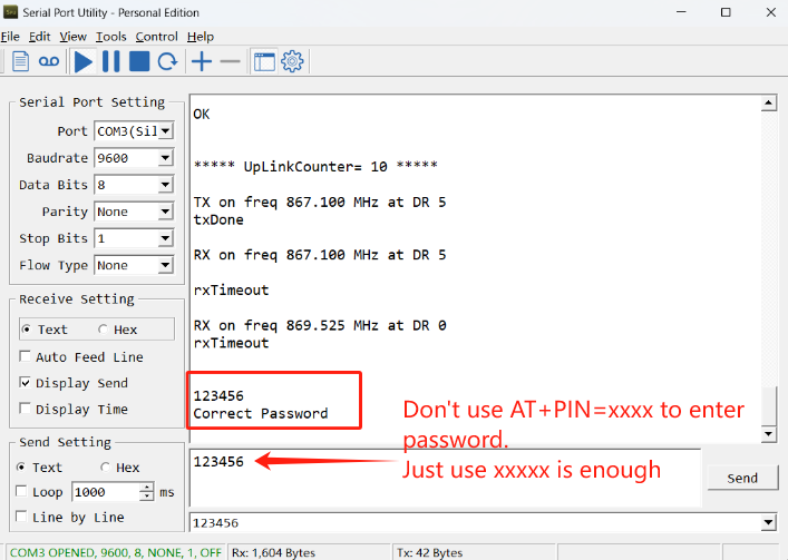
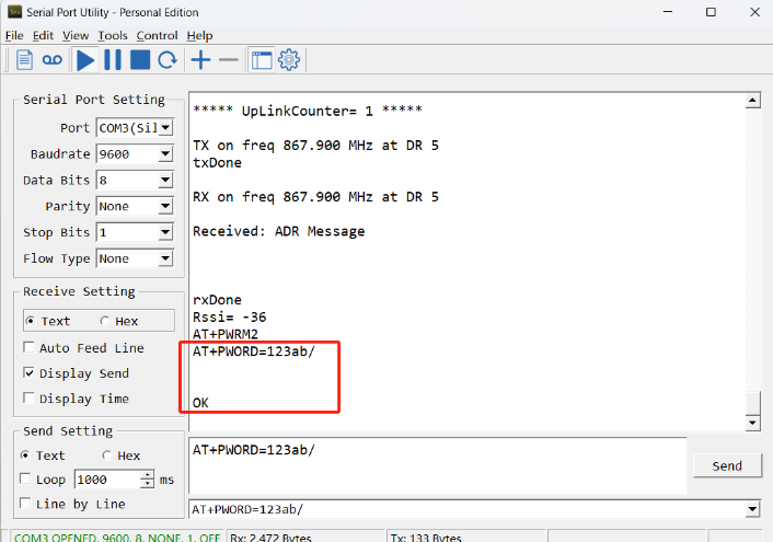
If you need to change the password, use AT+PWORD=xxxxxx (6 characters), NB nodes only support lowercase letters.
Note: After entering the command, you need to add a line break, and you can also set automatic line breaks in the Bluetooth tool or UART connection tool.

3.3 AT Commands Set
AT+<CMD>? : Help on <CMD>
AT+<CMD> : Run <CMD>
AT+<CMD>=<value> : Set the value
AT+<CMD>=? : Get the value
General Commands
AT : Attention
AT? : Short Help
ATZ : MCU Reset
AT+TDC : Application Data Transmission Interval
AT+CFG : Print all configurations
AT+MODEL :Get module information
AT+SLEEP :Get or set the sleep status
AT+DEUI : Get or set the Device ID
AT+INTMOD : Set the trigger interrupt mode
AT+APN : Get or set the APN
AT+3V3T : Set extend the time of 3V3 power
AT+5VT : Set extend the time of 5V power
AT+12VT : Set extend the time of 12V power
AT+PROBE : Get or Set the probe model
AT+PRO : Choose agreement
AT+RXDL : Extend the sending and receiving time
AT+TR : Get or set data record time
AT+CDP : Read or Clear cached data
AT+NOUD : Get or Set the number of data to be uploaded
AT+DNSCFG : Get or Set DNS Server
AT+CSQTIME : Get or Set the time to join the network
AT+DNSTIMER : Get or Set the NDS timer
AT+TLSMOD : Get or Set the TLS mode
AT+GETSENSORVALUE : Returns the current sensor measurement
AT+SERVADDR : Server Address
MQTT Management
AT+CLIENT : Get or Set MQTT client
AT+UNAME : Get or Set MQTT Username
AT+PWD : Get or Set MQTT password
AT+PUBTOPIC : Get or Set MQTT publish topic
AT+SUBTOPIC : Get or Set MQTT subscription topic
Information
AT+FDR : Factory Data Reset
AT+PWORD : Serial Access Password
AT+LDATA : Get the last upload data
AT+CDP : Read or Clear cached data
4. Battery & Power Consumption
PS-NB-NA use ER26500 + SPC1520 battery pack. See below link for detail information about the battery info and how to replace.
Battery Info & Power Consumption Analyze .
5. Firmware update
User can change device firmware to::
- Update with new features.
- Fix bugs.
Firmware and changelog can be downloaded from : Firmware download link
Methods to Update Firmware:
- (Recommended way) OTA firmware update via BLE: Instruction.
- Update through UART TTL interface : Instruction.
6. FAQ
6.1 How can I access t BC660K-GL AT Commands?
User can access to BC660K-GL directly and send AT Commands.
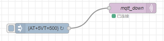
6.2 How to configure the device through the MQTT subscription function? (Since version v1.0.3)
Subscription content: {AT COMMAND}
Example:
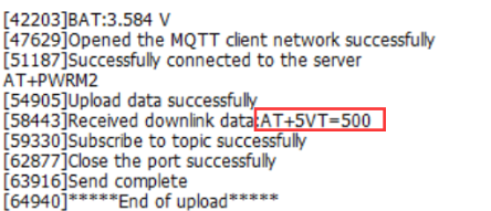
Setting AT+5VT=500 through Node-RED requires MQTT to send the content {AT+5VT=500}.
The serial port displays:
7. Order Info
Part Number: PS-NB-NA-XX-YY
XX:
- GE: General version ( Exclude SIM card)
- 1T: with 1NCE * 10 years 500MB SIM card and Pre-configure to ThingsEye server
YY: The grand connector hole size
- M12: M12 hole
- M16: M16 hole
- M20: M20 hole
8. Packing Info
Package Includes:
- PS-NB-NA NB-IoT Analog Sensor x 1
- External antenna x 1
Dimension and weight:
Package Size / pcs :
- For PS-NB-NA: 170*80*55 mm
- For PS-NS-NA: 160*105*45 mm
Weight / pcs :
- For PS-NB-NA: 250 g
- For PS-NS-NA: 285 g
9. Support
- Support is provided Monday to Friday, from 09:00 to 18:00 GMT+8. Due to different timezones we cannot offer live support. However, your questions will be answered as soon as possible in the before-mentioned schedule.
- Provide as much information as possible regarding your enquiry (product models, accurately describe your problem and steps to replicate it etc) and send a mail to Support@dragino.cc.