DDS04-LB/LS -- LoRaWAN 4-Channels Distance Detection Sensor User Manual
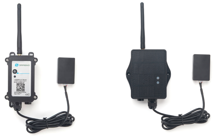
Table of Contents :
- 1. Introduction
- 2. Configure DDS04-LB/LS to connect to LoRaWAN network
- 3. Configure DDS04-LB/LS
- 4. Battery & Power Consumption
- 5. OTA Firmware update
- 6. FAQ
- 7. Trouble Shooting
- 8. Order Info
- 9. Packing Info
- 10. Support
1. Introduction
1.1 What is LoRaWAN 4-Channels Distance Sensor
The Dragino DDS04-LB/LS is a LoRaWAN 4-Channels Distance Sensor for Internet of Things solution. It is capable to add up to four Ultrasonic Sensors to measure four distances at the same time.
The DDS04-LB/LS can be applied to scenarios such as horizontal distance measurement, parking management system, object proximity and presence detection, intelligent trash can management system, robot obstacle avoidance, automatic control, sewer, etc.
It detects the distance between the measured object and the sensor, and uploads the value via wireless to LoRaWAN IoT Server.
The LoRa wireless technology used in DDS04-LB/LS allows device to send data and reach extremely long ranges at low data-rates. It provides ultra-long range spread spectrum communication and high interference immunity whilst minimizing current consumption.
DDS04-LB/LS supports BLE configure and wireless OTA update which make user easy to use.
DDS04-LB/LS is powered by 8500mAh Li-SOCI2 battery or solar powered + Li-ion battery, it is designed for long term use up to 5 years.
Each DDS04-LB/LS is pre-load with a set of unique keys for LoRaWAN registrations, register these keys to local LoRaWAN server and it will auto connect after power on.
1.2 Features
- LoRaWAN 1.0.3 Class A
- Bands: CN470/EU433/KR920/US915/EU868/AS923/AU915/IN865
- Ultra-low power consumption
- Detect Range: Base on External Probe
- Monitor Battery Level
- Support Bluetooth v5.1 and LoRaWAN remote configure
- Support wireless OTA update firmware
- AT Commands to change parameters
- Downlink to change configure
- 8500mAh Li/SOCl2 Battery (DDS04-LB)
- Solar panel + 3000mAh Li-ion battery (DDS04-LS)
1.3 Specification
Common DC Characteristics:
- Supply Voltage: Built-in Battery , 2.5v ~ 3.6v
- Operating Temperature: -40 ~ 85°C
LoRa Spec:
- Frequency Range, Band 1 (HF): 862 ~ 1020 Mhz
- Max +22 dBm constant RF output vs.
- RX sensitivity: down to -139 dBm.
- Excellent blocking immunity
Battery:
- Li/SOCI2 un-chargeable battery
- Capacity: 8500mAh
- Self-Discharge: <1% / Year @ 25°C
- Max continuously current: 130mA
- Max boost current: 2A, 1 second
Power Consumption
- Sleep Mode: 5uA @ 3.3v
- LoRa Transmit Mode: 125mA @ 20dBm, 82mA @ 14dBm
1.4 Probe Options
1.4.1 Probes Comparation
| Model | Photo | Description |
|---|---|---|
| A01A-15 |
| Detect Distance: 28 cm ~ 750 cm Blind Spot Distance: 0 ~ 28cm Accuracy: ±(1cm+S*0.3%) (S: Distance) Measure Angle: ~ 40° Cable Length: 1.5 meter Temperature Compensation Suitable for Flat Object Detect IP67 Water Proof |
| A02-15 |
| Detect Distance: 3cm ~ 450cm Blind Spot Distance: 0 ~ 3cm Accuracy: ±(1cm+S*0.3%) (S: Distance) Measure Angle: ~ 60° Cable Length: 1.5 meter Temperature Compensation Suitable for Flat Object Detect, Rubbish Bin IP67 Water Proof |
| A13-15 |
| Detect Distance: 25cm ~ 200cm Blind Spot Distance: 0 ~ 25cm Accuracy: ±(1cm+S*0.3%) (S: Distance) Measure Angle: ~ 20° Cable Length: 1.5 meter Temperature Compensation Suitable for Flat Object Detect, Rubbish Bin IP67 Water Proof |
| A16-15 |
| Detect Distance: 50cm ~ 1500cm Blind Spot Distance: 0 ~ 50cm Accuracy: ±(1cm+S*0.3%) (S: Distance) Measure Angle: ~ 40° Cable Length: 1.5 meter Temperature Compensation Suitable for Long Distance Detect IP67 Water Proof |


1.4.2 A01A-15 probe
A01A-15 is mainly used for plane distance measurement; it can carry out targeted measurement on plane objects and can measure long distances and high accuracy.
Beam Chart:
(1) The tested object is a white cylindrical tube made of PVC, with a height of 100cm and a diameter of 7.5cm.

(2) The object to be tested is a "corrugated cardboard box" perpendicular to the central axis of 0 °, and the length * width is 60cm * 50cm.

Mechanical:


Application:

1.4.3 A02-15 probe
Beam Chart:
(1) The tested object is a white cylindrical tube made of PVC, with a height of 100cm and a diameter of 7.5cm.

(2) The object to be tested is a "corrugated cardboard box" perpendicular to the central axis of 0 °, and the length * width is 60cm * 50cm.

Mechanical:

Application:

1.4.4 A13-15 probe
Beam Chart:
(1) The tested object is a white cylindrical tube made of PVC, with a height of 100cm and a diameter of 7.5cm.

(2) The object to be tested is a "corrugated cardboard box" perpendicular to the central axis of 0 °, and the length * width is 60cm * 50cm.
Mechanical:

Installation Requirement:

Application:

1.4.5 A13-16 probe
Beam Chart:
(1) The tested object is a white cylindrical tube made of PVC, with a height of 100cm and a diameter of 7.5cm.

(2) The object to be tested is a "corrugated cardboard box" perpendicular to the central axis of 0 °, and the length * width is 60cm * 50cm.

Mechanical:

Application:

1.5 Applications
- Horizontal distance measurement
- Parking management system
- Object proximity and presence detection
- Intelligent trash can management system
- Robot obstacle avoidance
- Automatic control
- Sewer
1.6 Sleep mode and working mode
Deep Sleep Mode: Sensor doesn't have any LoRaWAN activate. This mode is used for storage and shipping to save battery life.
Working Mode: In this mode, Sensor will work as LoRaWAN Sensor to Join LoRaWAN network and send out sensor data to server. Between each sampling/tx/rx periodically, sensor will be in IDLE mode), in IDLE mode, sensor has the same power consumption as Deep Sleep mode.
1.7 Button & LEDs

| Behavior on ACT | Function | Action |
|---|---|---|
 1~3s 1~3s | Send an uplink | If sensor is already Joined to LoRaWAN network, sensor will send an uplink packet, blue led will blink once. |
 >3s >3s | Active Device | Green led will fast blink 5 times, device will enter OTA mode for 3 seconds. And then start to JOIN LoRaWAN network. |
 x5 x5 | Deactivate Device | Red led will solid on for 5 seconds. Means device is in Deep Sleep Mode. |
1.8 BLE connection
DDS04-LB/LS support BLE remote configure.
BLE can be used to configure the parameter of sensor or see the console output from sensor. BLE will be only activate on below case:
- Press button to send an uplink
- Press button to active device.
- Device Power on or reset.
If there is no activity connection on BLE in 60 seconds, sensor will shut down BLE module to enter low power mode.
1.9 Pin Definitions

1.10 Mechanical
1.10.1 for LB version

1.10.2 for LS version

2. Configure DDS04-LB/LS to connect to LoRaWAN network
2.1 How it works
The DDS04-LB/LS is configured as LoRaWAN OTAA Class A mode by default. It has OTAA keys to join LoRaWAN network. To connect a local LoRaWAN network, you need to input the OTAA keys in the LoRaWAN IoT server and press the button to activate the DDS04-LB/LS. It will automatically join the network via OTAA and start to send the sensor value. The default uplink interval is 20 minutes.
2.2 Connect Probe
DDS04-LB/LS has a converter, User need to connect the Ultrasonic Probes to the convert as below. Different probes are supported, please see this link for the probe options.

Probe mapping as below.

2.3 Quick guide to connect to LoRaWAN server (OTAA)
Following is an example for how to join the TTN v3 LoRaWAN Network. Below is the network structure; we use the LPS8v2 as a LoRaWAN gateway in this example.
The LPS8v2 is already set to connected to TTN network , so what we need to now is configure the TTN server.

Step 1: Create a device in TTN with the OTAA keys from DDS04-LB/LS.
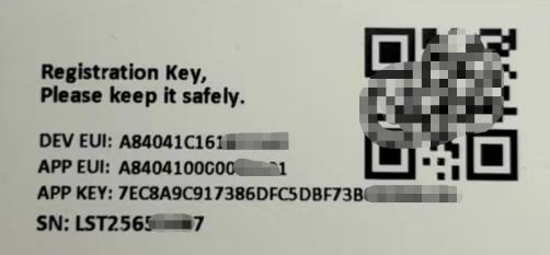
Each DDS04-LB/LS is shipped with a sticker with the default device EUI as below:
2.3.1 Creating an application
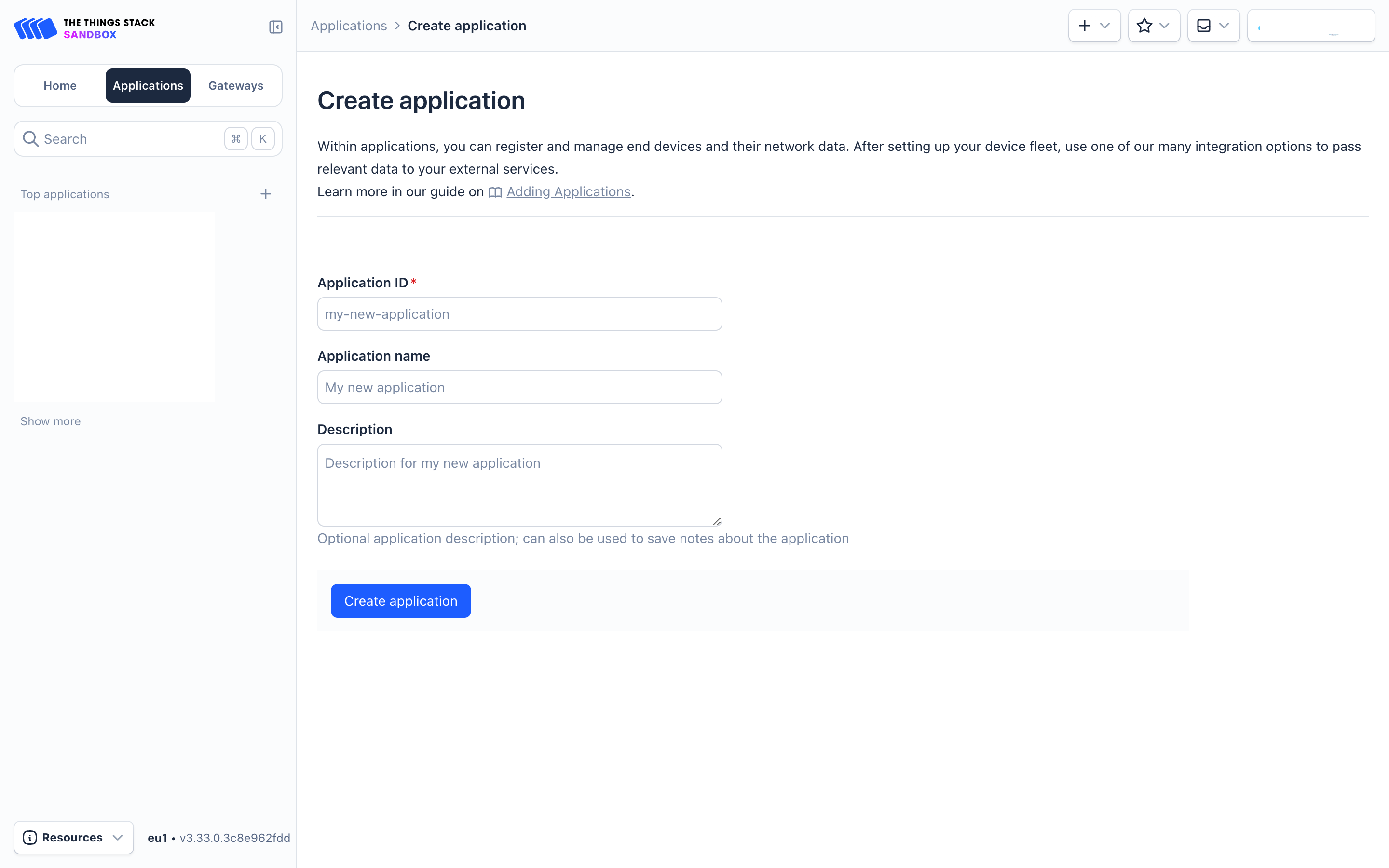
Sign up for a free account with The Things Stack Sandbox if you do not have one yet. Then, create an application as shown in the screenshots below.
Application ID: Provide a unique name to identify your application within The Things Stack, e.g., dragino-docs.
2.3.2 Adding manually
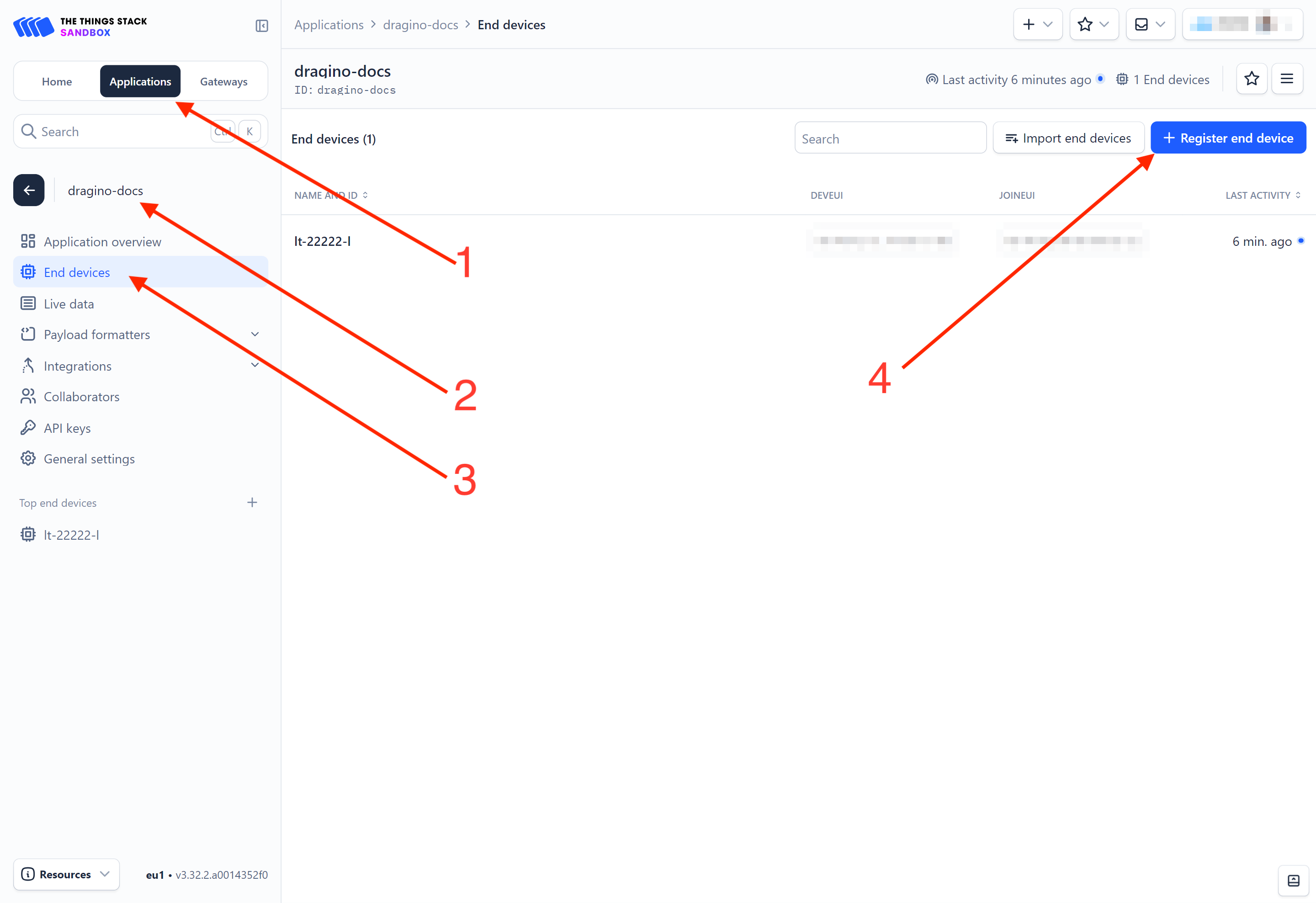
You can refer to the screenshots below to register your WQS-LB using The Things Stack's manual option.
On The Things Stack console:
1. Click Applications.
2. Click <your application>. E.g. dragino-docs
3 Click End devices.
4. Click + Register end device button.
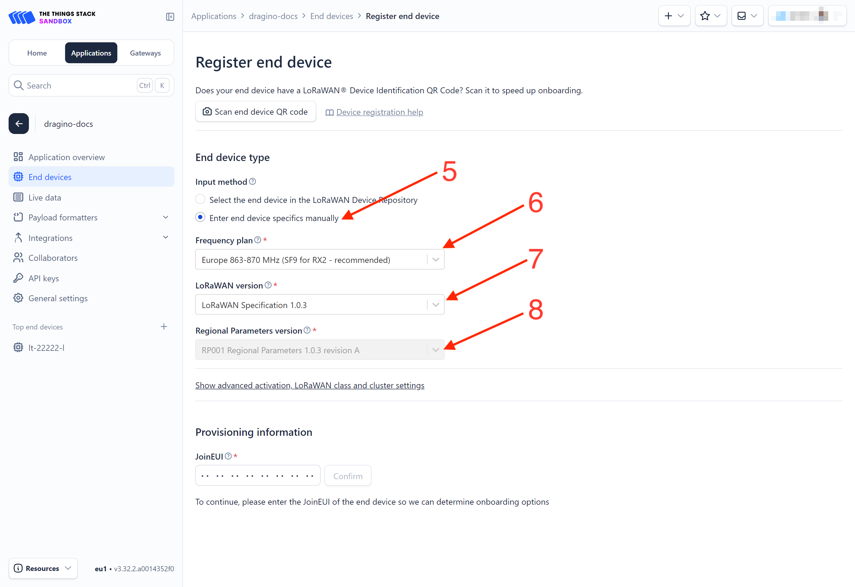
5. Select Enter end device specifies manually option.
6. Frequency plan: Select the frequency plan that matches your device. E.g.: Europe 863-870 MHz (SF9 for RX2 - recommended).
7. LoRaWAN version: LoRaWAN Specification 1.0.3
8. Regional Parameters version: You can't change it and it will select automatically.
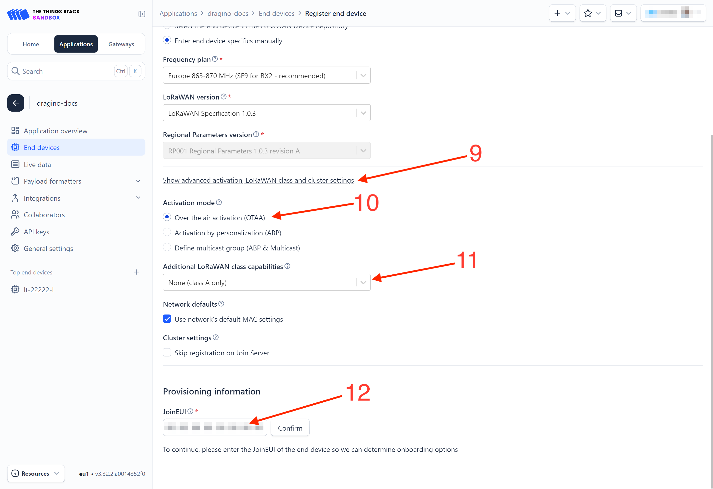
9. Click on the Show advanced activation, LoRaWAN class and cluster settings to expand the section.
10. Select Over the air activation (OTAA) option.
11. Select None (class A only).
12. JoinEUI: Enter the AppEUI of the device (see the registration information sticker) and Click the Confirm button.
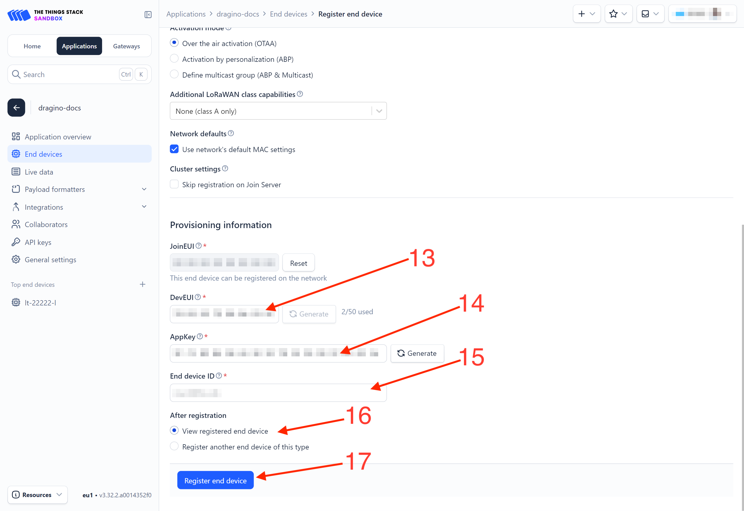
13. DevEUI: Enter the DevEUI of the device (see the registration information sticker).
14. AppKey: Enter the AppKey of the device (see the registration information sticker).
15. End device ID: Enter a name for your end device to uniquely identify it within this application.
16. Click View registered end device option.
17. Click Register end device button.
You will be navigated to the Device overview page.
Step 2: Activate on DDS04-LB/LS
Press the button for 5 seconds to activate the DDS04-LB/LS.
Green led will fast blink 5 times, device will enter OTA mode for 3 seconds. And then start to JOIN LoRaWAN network. Green led will solidly turn on for 5 seconds after joined in network.
After join success, it will start to upload messages to TTN and you can see the messages in the panel.
2.3.3 Uplink Decoder in The Things Stack
When the uplink payload arrives in The Things Stack, it is displayed in HEX format, which is not easy to read. You can add the WQS-LB decoder in The Things Stack for easier readability of each sensor reading.
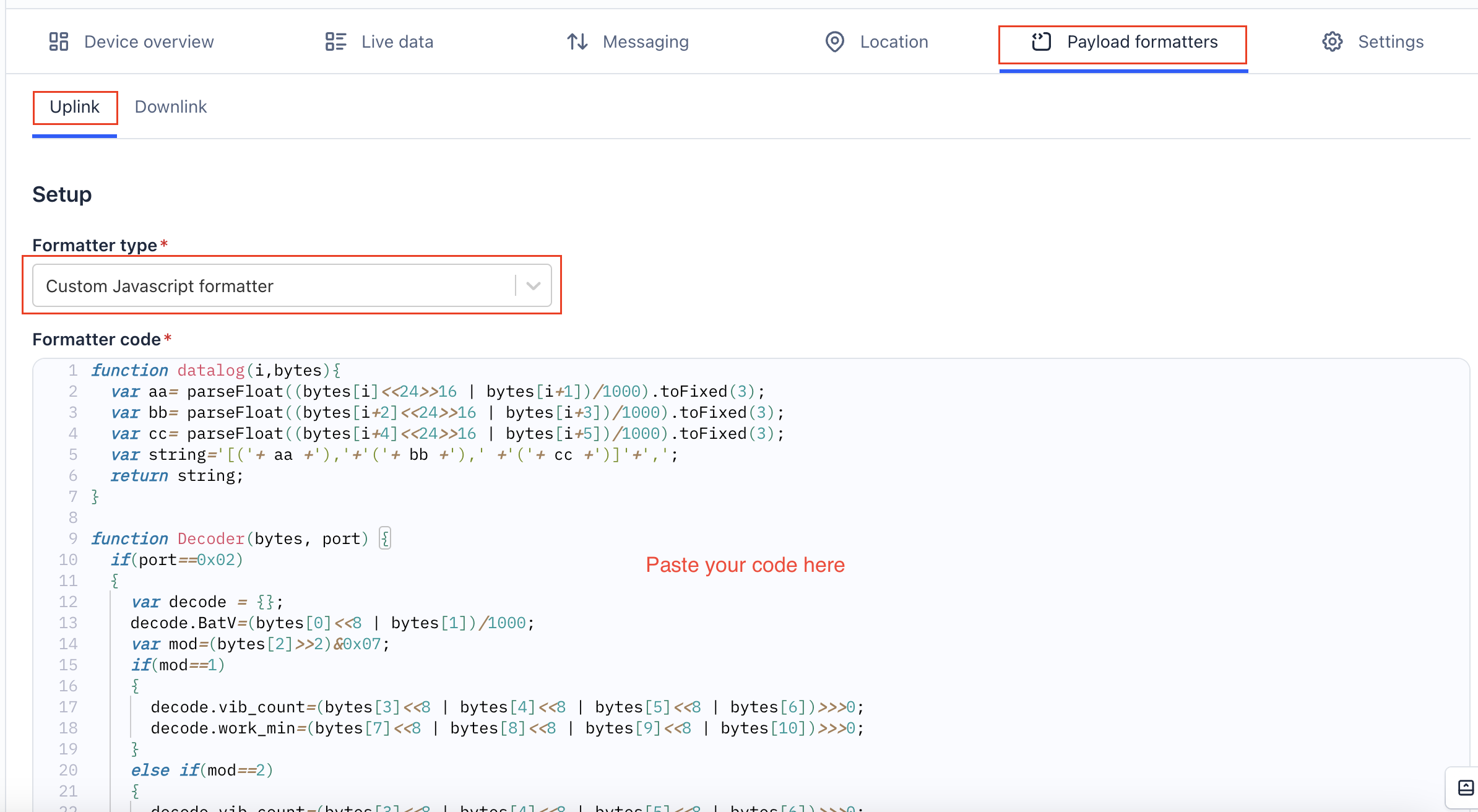
The uplink decoder can be added to the Payload Formatters of your device in The Things Stack. Refer to the screenshot below.
1. Click Uplink tab.
2. Formatter type: Select Custom Javascript formatter.
3. Formatter code: Copy the uplink payload formatter code from our dragino-end-node-decoder GitHub repository and paste it here.
4. Finally, click on the Save changes button.
2.4 Uplink Payload
2.4.1 Device Status, FPORT=5
Users can use the downlink command(0x26 01) to ask DDS04-LB/LS to send device configure detail, include device configure status. DDS04-LB/LS will uplink a payload via FPort=5 to server.
The Payload format is as below.
Size(bytes) | 1 | 2 | 1 | 1 | 2 |
|---|---|---|---|---|---|
| Value | Sensor Model | Firmware Version | Frequency Band | Sub-band | BAT |
Example parse in TTNv3
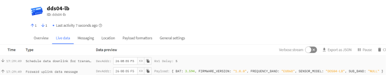
Sensor Model: For DDS04-LB/LS, this value is 0x23
Firmware Version: 0x0100, Means: v1.0.0 version
Frequency Band:
0x01: EU868
0x02: US915
0x03: IN865
0x04: AU915
0x05: KZ865
0x06: RU864
0x07: AS923
0x08: AS923-1
0x09: AS923-2
0x0a: AS923-3
0x0b: CN470
0x0c: EU433
0x0d: KR920
0x0e: MA869
Sub-Band:
AU915 and US915:value 0x00 ~ 0x08
CN470: value 0x0B ~ 0x0C
Other Bands: Always 0x00
Battery Info:
Check the battery voltage.
Ex1: 0x0B45 = 2885mV
Ex2: 0x0B49 = 2889mV
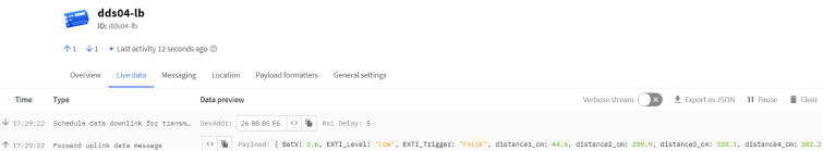
2.4.2 Uplink Payload, FPORT=2
DDS04-LB/LS will send this uplink after Device Status once join the LoRaWAN network successfully. And DDS04-LB/LS will:
periodically send this uplink every 20 minutes, this interval can be changed.
Uplink payload includes in total 11 bytes.
Size(bytes) | 2 | 2 | 2 | 2 | 2 | 1 |
|---|---|---|---|---|---|---|
| Value |
Battery Info
Check the battery voltage for DDS04-LB/LS.
Ex1: 0x0B45 & 0x3FFF = 2885mV
Ex2: 0x0B49 & 0x3FFF = 2889mV
Interrupt flag & Interrupt level
This data field shows if this packet is generated by interrupt or not. Click here for the hardware and software set up.
Note: The Internet Pin is a separate pin in the screw terminal. See pin mapping of GPIO_EXTI.
Example:
(0x0D4A & 0x4000) >>14 = 0: Normal uplink packet.
(0x4D41 & 0x4000) >>14 = 1: Interrupt Uplink Packet.
(0x0D4A & 0x8000) >>15 = 0: Pin of GPIO_EXTI is low level.
(0x8D41 & 0x8000) >>15 = 1: Pin of GPIO_EXTI is high level.
Distance
The measuring distance of the four distance measuring modules, the default unit is cm.
Example:
Uplink Payload: 0D 4A 03 16 03 18 03 1A 03 15 01
Data analysis:
Distance of UT sensor1 : 0316(H) = 790 (D)/10 = 79cm.
Distance of UT sensor2 : 0318(H) = 792 (D)/10 = 79.2cm.
Distance of UT sensor3 : 031A(H) = 794 (D)/10 = 79.4cm.
Distance of UT sensor4 : 0315(H) = 789 (D)/10 = 78.9cm.
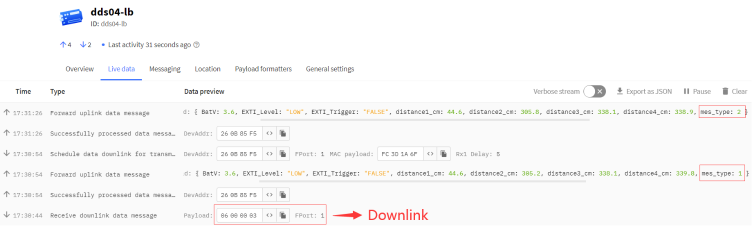
Message Type
For a normal uplink payload, the message type is always 0x01.
Valid Message Type:
| Message Type Code | Description | Payload |
|---|---|---|
| 0x01 | Normal Uplink | Normal Uplink Payload |
| 0x02 | Reply configures info | Configure Info Payload |
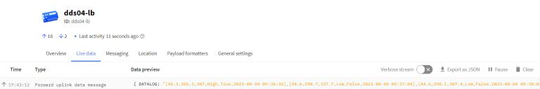
2.4.3 Historical measuring distance, FPORT=3
DDS04-LB/LS stores sensor values and users can retrieve these history values via the downlink command.
The historical payload includes one or multiplies entries and every entry has the same payload as Real-Time measuring distance.
Note: Due to the byte limit, the history record can only save the data of the first, second, third measurement distance channels.
Size(bytes) | 1 | 2 | 2 | 2 | 4 |
|---|---|---|---|---|---|
| Value | Interrupt flag & Interrupt_level | Distance1 | Distance2 | Distance3 | Unix TimeStamp |
Interrupt flag & Interrupt level:
Size(bit) | bit7 | bit7 | [bit5:bit2] | bit1 | bit0 |
|---|---|---|---|---|---|
| Value | No ACK message | Poll Message Flag | Reserve | Interrupt level | Interrupt flag |
Each data entry is 11 bytes and has the same structure as Uplink Payload, to save airtime and battery, DDS04-LB/LS will send max bytes according to the current DR and Frequency bands.
For example, in the US915 band, the max payload for different DR is:
a) DR0: max is 11 bytes so one entry of data
b) DR1: max is 53 bytes so devices will upload 4 entries of data (total 44 bytes)
c) DR2: total payload includes 11 entries of data
d) DR3: total payload includes 22 entries of data.
If DDS04-LB/LS doesn't have any data in the polling time. It will uplink 11 bytes of 0
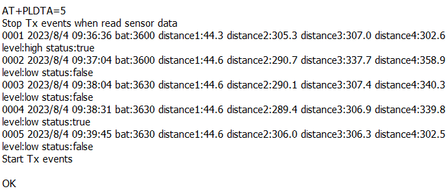
Downlink:
0x31 64 CC C6 9E 64 CC C7 70 05
Uplink:
43 01 BB 0B ED 0B FE 64 CC C6 A4 40 01 BE 0B 5B 0D 31 64 CC C6 C0 40 01 BE 0B 55 0C 02 64 CC C6 FC 41 01 BE 0B 4E 0B FD 64 CC C7 17 40 01 BE 0B F4 0B F7 64 CC C7 61
Parsed Value:
[DISTANCE1 , DISTANCE2,DISTANCE3,EXTI_STATUS , EXTI_FLAG , TIME]
[44.3,305.3,307,High,True,2023-08-04 09:36:36],
[44.6,290.7,337.7,Low,False,2023-08-04 09:37:04],
[44.6,290.1,307.4,Low,False,2023-08-04 09:38:04],
[44.6,289.4,306.9,Low,True,2023-08-04 09:38:31],
[44.6,306,306.3,Low,False,2023-08-04 09:39:45],
History read from serial port:
2.4.4 Decode payload in The Things Network
While using TTN network, you can add the payload format to decode the payload.

The payload decoder function for TTN is here:
DDS04-LB/LS TTN Payload Decoder: ttps://github.com/dragino/dragino-end-node-decoder
2.5 Show Data in DataCake IoT Server
DATACAKE provides a human friendly interface to show the sensor data, once we have data in TTN, we can use DATACAKE to connect to TTN and see the data in DATACAKE. Below are the steps:
Step 1: Be sure that your device is programmed and properly connected to the network at this time.
Step 2: To configure the Application to forward data to DATACAKE you will need to add integration. To add the DATACAKE integration, perform the following steps:


Step 3: Create an account or log in Datacake.
Step 4: Search the DDS04-LB/LS and add DevEUI.


Step 5: Add payload decode


After added, the sensor data arrive TTN, it will also arrive and show in Datacake.


2.6 Datalog Feature
Datalog Feature is to ensure IoT Server can get all sampling data from Sensor even if the LoRaWAN network is down. For each sampling, DDS04-LB/LS will store the reading for future retrieving purposes.
2.6.1 Ways to get datalog via LoRaWAN
Set PNACKMD=1, DDS04-LB/LS will wait for ACK for every uplink, when there is no LoRaWAN network, DDS04-LB/LS will mark these records with non-ack messages and store the sensor data, and it will send all messages (10s interval) after the network recovery.
a) DDS04-LB/LS will do an ACK check for data records sending to make sure every data arrive server.
b) DDS04-LB/LS will send data in CONFIRMED Mode when PNACKMD=1, but DDS04-LB/LS won't re-transmit the packet if it doesn't get ACK, it will just mark it as a NONE-ACK message. In a future uplink if DDS04-LB/LS gets a ACK, DDS04-LB/LS will consider there is a network connection and resend all NONE-ACK messages.
2.6.2 Unix TimeStamp
DDS04-LB/LS uses Unix TimeStamp format based on

User can get this time from link: https://www.epochconverter.com/ :
Below is the converter example

So, we can use AT+TIMESTAMP=1611889405 or downlink 3060137afd00 to set the current time 2021 – Jan -- 29 Friday 03:03:25
2.6.3 Set Device Time
User need to set SYNCMOD=1 to enable sync time via MAC command.
Once DDS04-LB/LS Joined LoRaWAN network, it will send the MAC command (DeviceTimeReq) and the server will reply with (DeviceTimeAns) to send the current time to DDS04-LB/LS. If DDS04-LB/LS fails to get the time from the server, DDS04-LB/LS will use the internal time and wait for next time request (AT+SYNCTDC to set the time request period, default is 10 days).
Note: LoRaWAN Server need to support LoRaWAN v1.0.3(MAC v1.0.3) or higher to support this MAC command feature, Chirpstack,TTN V3 v3 and loriot support but TTN V3 v2 doesn't support. If server doesn't support this command, it will through away uplink packet with this command, so user will lose the packet with time request for TTN V3 v2 if SYNCMOD=1.
2.6.4 Poll sensor value
Users can poll sensor values based on timestamps. Below is the downlink command.
| Downlink Command to poll Open/Close status (0x31) | |||
| 1byte | 4bytes | 4bytes | 1byte |
| 31 | Timestamp start | Timestamp end | Uplink Interval |
Timestamp start and Timestamp end-use Unix TimeStamp format as mentioned above. Devices will reply with all data logs during this period, using the uplink interval.
For example, downlink command 
Is to check 2021/11/12 12:00:00 to 2021/11/12 15:00:00's data
Uplink Internal =5s,means DDS04-LB/LS will send one packet every 5s. range 5~255s.
2.7 Frequency Plans
The DDS04-LB/LS uses OTAA mode and below frequency plans by default. Each frequency band use different firmware, user update the firmware to the corresponding band for their country.
http://wiki.dragino.com/xwiki/bin/view/Main/End%20Device%20Frequency%20Band/
3. Configure DDS04-LB/LS
3.1 Configure Methods
DDS04-LB/LS supports below configure method:
- AT Command via Bluetooth Connection (Recommended): BLE Configure Instruction.
- AT Command via UART Connection : See UART Connection.
- LoRaWAN Downlink. Instruction for different platforms: See IoT LoRaWAN Server section.
3.2 General Commands
These commands are to configure:
- General system settings like: uplink interval.
- LoRaWAN protocol & radio related command.
They are same for all Dragino Devices which support DLWS-005 LoRaWAN Stack. These commands can be found on the wiki:
http://wiki.dragino.com/xwiki/bin/view/Main/End%20Device%20AT%20Commands%20and%20Downlink%20Command/
3.3 Commands special design for DDS04-LB/LS
These commands only valid for DDS04-LB/LS, as below:
3.3.1 Set Transmit Interval Time
Feature: Change LoRaWAN End Node Transmit Interval.
AT Command: AT+TDC
| Command Example | Function | Response |
|---|---|---|
| AT+TDC=? | Show current transmit Interval | 30000 |
| AT+TDC=60000 | Set Transmit Interval | OK |
Downlink Command: 0x01
Format: Command Code (0x01) followed by 3 bytes time value.
If the downlink payload=0100003C, it means set the END Node's Transmit Interval to 0x00003C=60(S), while type code is 01.
Example 1: Downlink Payload: 0100001E // Set Transmit Interval (TDC) = 30 seconds
Example 2: Downlink Payload: 0100003C // Set Transmit Interval (TDC) = 60 seconds
3.3.2 Set Interrupt Mode
Feature, Set Interrupt mode for pin of GPIO_EXTI.
When AT+INTMOD=0 is set, GPIO_EXTI is used as a digital input port.
AT Command: AT+INTMOD
| Command Example | Function | Response |
|---|---|---|
| AT+INTMOD=? | Show current interrupt mode | 0 |
AT+INTMOD=2 (default) | Set Transmit Interval | OK |
Downlink Command: 0x06
Format: Command Code (0x06) followed by 3 bytes.
This means that the interrupt mode of the end node is set to 0x000003=3 (rising edge trigger), and the type code is 06.
- Example 1: Downlink Payload: 06000000 // Turn off interrupt mode
- Example 2: Downlink Payload: 06000003 // Set the interrupt mode to rising edge trigger
3.3.3 Set Power Output Duration
Control the output duration 3V3 (pin of VBAT_OUT). Before each sampling, device will
1. first enable the power output to external sensor,
2. keep it on as per duration, read sensor value and construct uplink payload
3. final, close the power output.
AT Command: AT+3V3T
| Command Example | Function | Response |
|---|---|---|
| AT+3V3T=? | Show 3V3 open time. | 0 (default) OK |
| AT+3V3T=1000 | Close after a delay of 1000 milliseconds. | OK |
| AT+3V3T=0 | Always turn on the power supply of 3V3 pin. | OK |
| AT+3V3T=65535 | Always turn off the power supply of 3V3 pin. | OK |
Downlink Command: 0x07
Format: Command Code (0x07) followed by 3 bytes.
The first byte is 01,the second and third bytes are the time to turn on.
- Example 1: Downlink Payload: 07 01 00 00 ---> AT+3V3T=0
- Example 2: Downlink Payload: 07 01 01 F4 ---> AT+3V3T=500
- Example 3: Downlink Payload: 07 01 FF FF ---> AT+3V3T=65535
3.3.4 Set enable or disable of the measurement channel
This command can be used when user connects less than four distance sensors. This command can turn off unused measurement channels to save battery life.
AT Command: AT+ENCHANNEL
| Command Example | Function | Response |
|---|---|---|
| AT+ENCHANNEL=? | Get enabled channels. | 1,1,1,1 (default) OK |
| AT+ENCHANNEL=1,1,1,0 | Channel 4 disabled. | OK |
| AT+ENCHANNEL=1,1,0,0 | Channel 3 and 4 disabled. | OK |
Downlink Command: 0x08
Format: Command Code (0x08) followed by 4 bytes.
The first byte means the first channel, the second byte means the second channel, the third byte means the third channel, and the fourth byte means the fourth channel.And 1 means enable channel, 0 means disable channel.
- Example 1: Downlink Payload: 08 01 01 01 01 ---> AT+ENCHANNEL=1,1,1,1 //All channels are enabled
- Example 2: Downlink Payload: 08 01 01 01 00 ---> AT+ENCHANNEL=1,1,1,0 //Channel 4 disabled
- Example 3: Downlink Payload: 08 01 01 00 00 ---> AT+ENCHANNEL=1,1,0,0 //Channel 3 and 4 disabled
4. Battery & Power Consumption
DDS04-LB use ER26500 + SPC1520 battery pack and DDS04-LS use 3000mAh Recharable Battery with Solar Panel. See below link for detail information about the battery info and how to replace.
Battery Info & Power Consumption Analyze .
5. OTA Firmware update
User can change firmware DDS04-LB/LS to:
- Change Frequency band/ region.
- Update with new features.
- Fix bugs.
Firmware and changelog can be downloaded from : Firmware download link
Methods to Update Firmware:
- (Recommanded way) OTA firmware update via wireless: http://wiki.dragino.com/xwiki/bin/view/Main/Firmware%20OTA%20Update%20for%20Sensors/
- Update through UART TTL interface: Instruction.
6. FAQ
6.1 What is the frequency plan for DDS04-LB/LS?
DDS04-LB/LS use the same frequency as other Dragino products. User can see the detail from this link: Introduction
7. Trouble Shooting
7.1 Why I can't join TTN V3 in US915 / AU915 bands?
It is due to channel mapping. Please see below link: Frequency band
7.2 AT Command input doesn't work
In the case if user can see the console output but can't type input to the device. Please check if you already include the ENTER while sending out the command. Some serial tool doesn't send ENTER while press the send key, user need to add ENTER in their string.
7.3 Why does the sensor reading show 0 or "No sensor"
1. The measurement object is very close to the sensor, but in the blind spot of the sensor.
2. Sensor wiring is disconnected
3. Not using the correct decoder
8. Order Info
8.1 Main Device DDS04-LB/LS
Part Number : DDS04-LB-XX or DDS04-LS-XX
XX: The default frequency band
- AS923 : LoRaWAN AS923 band
- AU915 : LoRaWAN AU915 band
- EU433 : LoRaWAN EU433 band
- EU868 : LoRaWAN EU868 band
- KR920 : LoRaWAN KR920 band
- US915 : LoRaWAN US915 band
- IN865 : LoRaWAN IN865 band
- CN470 : LoRaWAN CN470 band
8.2 Probe Model
Detail See Probe Option Section
- A01A-15
- A02-15
- A13-15
- A16-15
9. Packing Info
Package Includes:
- DDS04-LB or DDS04-LS LoRaWAN 4-Channels Distance Detection Sensor x 1
Dimension and weight:
- Device Size: cm
- Device Weight: g
- Package Size / pcs : cm
- Weight / pcs : g
10. Support
- Support is provided Monday to Friday, from 09:00 to 18:00 GMT+8. Due to different timezones we cannot offer live support. However, your questions will be answered as soon as possible in the before-mentioned schedule.
- Provide as much information as possible regarding your enquiry (product models, accurately describe your problem and steps to replicate it etc) and send a mail to Support@dragino.cc.