WQS-NB/NS--NB-IoT Water Quality Sensor Transmitter User Manual

Table of Contents:
- 1. Introduction
- 2. How to use
- 3. Configure WQS-NB/NS
- 4. Water Qualit Sensors
- 5. Battery & Power Consumption
- 6. Firmware update
- 7. Packing Info
- 8. Sensors
- 9. Support
1. Introduction
1.1 Overview
WQS-NB/NS is a Main Unit is advanced instruments designed for comprehensive water quality monitoring across various applications. They are ideal for monitoring tap water, industrial water, environmental water, and wastewater,etc,which ofer precise and reliable measurements to ensure water quality standards are met.
WQS-NB/NS is a Main Unit supports 1-3 probes. supports connecting 1 to 3 water quality probes, including EC, pH, DO, ORP, and TS probes.
The Dragino WQS-NB/NS is a NB-IoT Analog Sensor for Internet of Things solution.
WQS-NB/NS will convert the Analog Value to NB-IoT wireless data and send to IoT platform via NB-IoT network.
WQS-NB/NS supports different uplink methods including MQTT, MQTTs, UDP, TCP or CoAP for different application requirement, and support uplinks to various IoT Servers.
WQS-NB/NS supports BLE configure and wireless OTA update which makes user easy to use.
WQS-NB/NS is powered by 8500mAh Li-SOCI2 battery or solar powered+Li-ion battery , it is designed for long-term use up to several years.
1.2 Specifications
Common DC Characteristics:
- Supply Voltage: 2.5v ~ 3.6v
- Operating Temperature: -40 ~ 85°C
I/O Interface:
- Battery controllable output (2.6v ~ 3.6v depends on battery)
- +5v controllable output
- 1 x RS485 Interface
- 1 x UART Interface , 3.3v or 5v
- 1 x Interrupt or Digital IN/OUT pins
- 1 x I2C Interface
- 1 x one wire interface
NB-IoT Spec:
NB-IoT Module: BC660K-GL
Support Bands:
- B1 @H-FDD: 2100MHz
- B2 @H-FDD: 1900MHz
- B3 @H-FDD: 1800MHz
- B4 @H-FDD: 2100MHz
- B5 @H-FDD: 860MHz
- B8 @H-FDD: 900MHz
- B12 @H-FDD: 720MHz
- B13 @H-FDD: 740MHz
- B17 @H-FDD: 730MHz
- B18 @H-FDD: 870MHz
- B19 @H-FDD: 870MHz
- B20 @H-FDD: 790MHz
- B25 @H-FDD: 1900MHz
- B28 @H-FDD: 750MHz
- B66 @H-FDD: 2000MHz
- B70 @H-FDD: 2000MHz
- B85 @H-FDD: 700MHz
Battery:
- Li/SOCI2 un-chargeable battery
- Capacity: 8500mAh
- Self Discharge: <1% / Year @ 25°C
- Max continuously current: 130mA
- Max boost current: 2A, 1 second
Power Consumption
- STOP Mode: 10uA @ 3.3v
- Max transmit power: 350mA@3.3v
1.3 Features
- NB-IoT Bands: B1/B2/B3/B4/B5/B8/B12/B13/B17/B18/B19/B20/B25/B28/B66/B70/B85 @H-FDD
- Ultra-low power consumption
- Measure water quality and provide information for water quality conditions
- Support EC / PH / DO / ORP/ TS Type Water Quality Probe
- Support 1 ~ 3 probes
- Multiply Sampling and one uplink
- Support Bluetooth v5.1 remote configure and update firmware
- Uplink via MQTT, MQTTs, TCP, UDP or CoAP
- AT Commands to change parameters
- Uplink on periodically
- Downlink to change configure
- 8500mAh Li/SOCl2 Battery (WQS-NB)
- Solar panel + 3000mAh Li-ion battery (WQS-NS)
1.4 Applications
- Smart Buildings & Home Automation
- Logistics and Supply Chain Management
- Smart Metering
- Smart Agriculture
- Smart Cities
- Smart Factory
1.5 Sleep mode and working mode
Deep Sleep Mode: Sensor doesn't have any NB-IoT activate. This mode is used for storage and shipping to save battery life.
Working Mode: In this mode, Sensor will work as NB-IoT Sensor to Join NB-IoT network and send out sensor data to server. Between each sampling/tx/rx periodically, sensor will be in IDLE mode), in IDLE mode, sensor has the same power consumption as Deep Sleep mode.
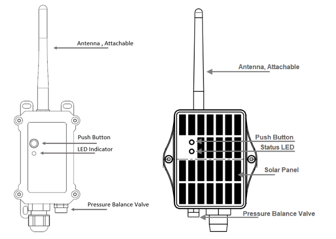
1.6 Button & LEDs
| Behavior on ACT | Function | Action |
|---|---|---|
| Pressing ACT between 1s < time < 3s | Send an uplink |
If sensor is already Joined to LoRaWAN network, sensor will send an uplink packet, blue led will blink once. |
| Pressing ACT for more than 3s | Active Device |
Green led will fast blink 5 times, device will enter OTA mode for 3 seconds. And then start to JOIN LoRaWAN network. |
| Fast press ACT 5 times. | Deactivate Device | Red led will solid on for 5 seconds. Means device is in Deep Sleep Mode. |
1.7 BLE connection
WQS-NB/NS supports BLE remote configure.
BLE can be used to configure the parameter of sensor or see the console output from sensor. BLE will be only activate on below case:
- Press button to send an uplink
- Press button to active device.
- Device Power on or reset.
If there is no activity connection on BLE in 60 seconds, sensor will shut down BLE module to enter low power mode.
1.8 Pin Definitions , Switch & SIM Direction

1.8.1 Jumper JP2
Power on Device when put this jumper.
1.8.2 BOOT MODE / SW1
1) ISP: upgrade mode, device won't have any signal in this mode. but ready for upgrade firmware. LED won't work. Firmware won't run.
2) Flash: work mode, device starts to work and send out console output for further debug
1.8.3 Reset Button
Press to reboot the device.
1.8.4 SIM Card Direction
See this link. How to insert SIM Card.
1.8.5 SW2 Jumper (Define UART level to external Sensor)
SW2 defines the voltage level of BOARD_RX and BOARD_TX pins. It should match the external sensor voltage level
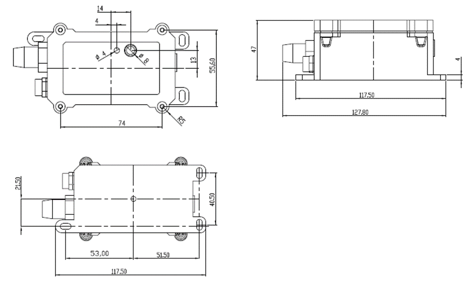
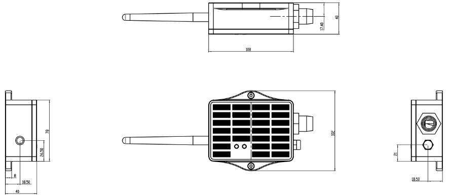
1.9 Mechanical
1.9.1 for NB version
1.9.2 for NS version
2. How to use
2.1 Example to use for IoT network
The WQS-NB/NS is equipped with a NB-IoT module, the pre-loaded firmware in WQS-NB/NS will get environment data from sensors and send the value to local NB-IoT network via the NB-IoT module. The NB-IoT network will forward this value to IoT server via the protocol defined by WQS-NB/NS.
Below shows the network structure:

There are two version: -GE and -1T version of WQS-NB/NS.
GE Version: This version doesn't include SIM card or point to any IoT server. User needs to use AT Commands to configure below two steps to set WQS-NB/NS send data to IoT server.
- Install NB-IoT SIM card and configure APN. See instruction of Attach Network.
- Set up sensor to point to IoT Server. See instruction of Configure to Connect Different Servers.
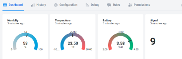
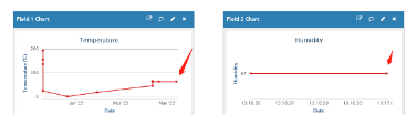
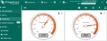
Below shows result of different server as a glance.
| Servers | Dash Board | Comments |
| Node-Red |
| |
| DataCake |
| |
| Tago.IO |  | |
| General UDP | Raw Payload. Need Developer to design Dash Board | |
| General MQTT | Raw Payload. Need Developer to design Dash Board | |
| ThingSpeak |
| |
| ThingsBoard |
|
1T Version: This version has 1NCE SIM card pre-installed and configure to send value to ThingsEye. User Just need to select the sensor type in ThingsEyeand Activate WQS-NB/NS and user will be able to see data in ThingsEye. See here for ThingsEye Config Instruction.
2.2 Uplink Payload
To meet different server requirement, WQS-NB/NS supports different payload type.
Includes:
- General JSON format payload. (Type=5)
- HEX format Payload. (Type=0)
- ThingSpeak Format. (Type=1)
- ThingsBoard Format. (Type=3)
User can specify the payload type when choose the connection protocol. Example:
AT+PRO=2,0 // Use UDP Connection & hex Payload
AT+PRO=2,5 // Use UDP Connection & Json Payload
AT+PRO=3,0 // Use MQTT Connection & hex Payload
AT+PRO=3,1 // Use MQTT Connection & ThingSpeak
AT+PRO=3,3 // Use MQTT Connection & ThingsBoard
AT+PRO=3,5 // Use MQTT Connection & Json Payload
AT+PRO=4,0 // Use TCP Connection & hex Payload
AT+PRO=4,5 // Use TCP Connection & Json Payload
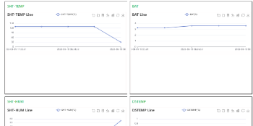
2.2.1 General Json Format(Type=5)
This is the General Json Format. As below:
{"IMEI":"863663062798971","Model":"WQS01-NB","DO":8.17,"EC_K1":572,"interrupt":0,"interrupt_level":0,"battery":3.56,"signal":21,"1":[8.17,573,"2024/09/24 06:07:57"],"2":[8.17,573,"2024/09/24 05:52:57"],"3":[8.17,573,"2024/09/24 05:37:57"],"4":[8.16,573,"2024/09/24 05:22:57"],"5":[8.16,573,"2024/09/24 05:07:57"],"6":[8.15,574,"2024/09/24 04:52:57"],"7":[8.14,575,"2024/09/24 04:37:57"],"8":[8.13,575,"2024/09/24 04:22:57"]}

Notice, from above payload:
- Idc_input , Vdc_input , Battery & Signal are the value at uplink time.
- Json entry 1 ~ 8 are the last 1 ~ 8 sampling data as specify by AT+CLOCKLOG=1,65535,15,8 Command. Each entry includes (from left to right): Idc_input , Vdc_input, Sampling time.
2.2.2 HEX format Payload(Type=0)
f866207058378443f46008351350732036660dd71701000003059202916749394d059202916749375d058f0291674933e80589029167492dec0589029167492ac7057f0291674926e4059d029167492360059b029067491fdc05920290674832ad


Version:
These bytes include the hardware and software version.
Higher byte: Specify Sensor Model: 0x68 for WQS-NB
Lower byte: Specify the software version: 0x66=102, means firmware version 1.0.2
BAT (Battery Info):
Ex1: 0x0dd7 = 3543mV
Signal :
NB-IoT Network signal Strength.
Ex1: 0x1f = 31
0 -113dBm or less
1 -111dBm
2...30 -109dBm... -53dBm
31 -51dBm or greater
99 Not known or not detectable
Interrupt:
This data field shows if this packet is generated by interrupt or not.
Example:
If byte[0]&0x01=0x00 : Normal uplink packet.
If byte[0]&0x01=0x01 : Interrupt Uplink Packet.
Interrupt_level:
This byte shows whether the interrupt is triggered by a high or low level.
Ex1: 0x00 Interrupt triggered by falling edge (low level)
Ex2: 0x01 Interrupt triggered by rising edge (high level)
Sensor flag:
There are six types of water quality sensors, each of which is assigned a position in the memory
000000, in order: TS1\DO1\ORP\ECK1\ECK10\PH01
In the example, PH01 and ECK1 are used, so 0x03 = 00000011
Sensor DATA:
The sensor data is uploaded in order from left to right.
As mentioned above, the sensors I connected are ECK1 and PH01, and the flag is 000011.
so the first one is the data of the ECK1 sensor, and the second one is the data of PH01.
Example:
ECK1=0x0592=1426
PH01=0x0291/100=6.57
2.2.3 ThingsBoard Payload(Type=3)
Type3 payload special design for ThingsBoard, it will also configure other default server to ThingsBoard.
{
"topic": "65CB_PUB",
"payload": {
"IMEI": "863663062798971",
"Model": "WQS01-NB",
"DO": 8.19,
"EC_K1": 572,
"interrupt": 0,
"interrupt_level": 0,
"battery": 3.54,
"signal": 17,
"1": [8.19, 572, "2024/09/24 07:22:59"],
"2": [8.19, 572, "2024/09/24 07:07:57"],
"3": [8.19, 572, "2024/09/24 06:52:57"],
"4": [8.19, 572, "2024/09/24 06:37:57"],
"5": [8.18, 572, "2024/09/24 06:22:57"],
"6": [8.17, 573, "2024/09/24 06:07:57"],
"7": [8.17, 573, "2024/09/24 05:52:57"],
"8": [8.17, 573, "2024/09/24 05:37:57"]
}
}

2.2.4 ThingSpeak Payload(Type=1)
This payload meets ThingSpeak platform requirement. It includes only four fields. Form 1~4 are:
Temperature, Humidity, Battery & Signal. This payload type only valid for ThingsSpeak Platform
As below:
field1=Tem&field2=Hum&field3=BatV&field4=Singal

3. Configure WQS-NB/NS
3.1 Configure Methods
WQS-NB/NS supports below configure method:
- AT Command via Bluetooth Connection (Recommended): BLE Configure Instruction.
- AT Command via UART Connection : See UART Connection.
3.2 Serial Access Password
After the Bluetooth or UART connection is successful, use the Serial Access Password to enter the AT command window.
The label on the box of the node will print the initial password: AT+PIN=xxxxxx, and directly use the six-digit password to access the AT instruction window.

If you need to change the password, use AT+PWORD=xxxxxx (6 characters), NB nodes only support lowercase letters.
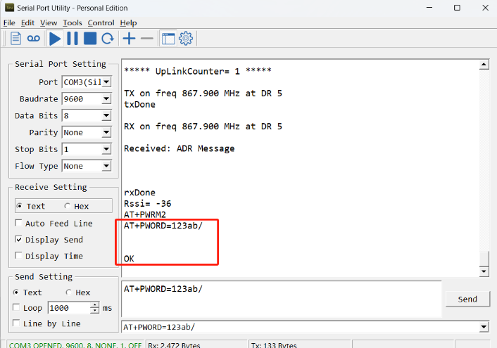
Note: After entering the command, you need to add a line break, and you can also set automatic line breaks in the Bluetooth tool or UART connection tool.

3.3 AT Commands Set
AT+<CMD>? : Help on <CMD>
AT+<CMD> : Run <CMD>
AT+<CMD>=<value> : Set the value
AT+<CMD>=? : Get the value
General Commands
AT : Attention
AT? : Short Help
ATZ : MCU Reset
AT+TDC : Application Data Transmission Interval
AT+CFG : Print all configurations
AT+CFGMOD : Working mode selection
AT+DEUI : Get or set the Device ID
AT+PRO : Choose agreement
AT+RXDL : Extend the sending and receiving time
AT+DNSCFG : Get or Set DNS Server
AT+GETSENSORVALUE : Returns the current sensor measurement
AT+SERVADDR : Server Address
AT+MOD: Get or Set work mode
AT+5VT : Get or Set extend the time of 5V power
AT+3V3T : Get or Set extend the time of 3V3 power
AT+INTMOD : Get or Set the trigger interrupt mode (0:input,1:falling or rising,2:falling,3:rising)
AT+BAUDR: Get or Set baudr of uart
AT+DATABIT: Get or Set databit(7:7 bit,8:8 bit) of uart
AT+PARITY: Get or Set parity(0:none,1:odd,2:even) of uart
AT+STOPBIT: Get or Set stopbit(0:1 bit,1:1.5 bit,2:2 bit) of uart
AT+CMDEAR: Erase command(number of begin to number of ending)
AT+PAYVER: Get or Set payload version
AT+MBFUN: Get or Set Modbus Funtion code(0:none,1:01 or 02,2:03 or 04)for automatic cut
AT+SEARCH: Retrieve the hexadecimal character that appears in command 1-15
AT+DATACUT: Cut receive data after use command1-15
AT+DNSTIMER: Regularly resolve domain names
MQTT Management
AT+CLIENT : Get or Set MQTT client
AT+UNAME : Get or Set MQTT Username
AT+PWD : Get or Set MQTT password
AT+PUBTOPIC : Get or Set MQTT publish topic
AT+SUBTOPIC : Get or Set MQTT subscription topic
Information
AT+FDR : Factory Data Reset
AT+PWORD : Serial Access Password
AT+LDATA : Get the last upload data
4. Water Qualit Sensors
4.1 PH Sensor
PH01 is a device for measuring the pH value (hydrogen ion concentration index, acidity and alkalinity) of a solution.
It adopts an integrated design, is lighter and simpler in structure, and is more convenient to use. The waterproof grade is IP68.
The reference electrode adopts a double salt bridge design, which has stronger anti-pollution ability.
This product is suitable for industrial sewage, domestic sewage, agriculture, aquaculture and other scenes in non-corrosive weak acid and weak alkali environments.
4.1.1 Feature
- pH measurement range 0~14pH, resolution 0.01pH.
- One-piece design, light and simple structure, easy to use.
- The reference adopts a double salt bridge design, which has stronger anti-pollution ability and waterproof grade IP68.
- The equipment adopts a wide voltage power supply DC 7~30V.
4.1.2 Specification
- Power supply: DC7~30V
- Power consumption: ≤0.5W
- Communication interface: RS485; standard MODBUS-RTU protocol; communication baud rate: default 9600
- pH measurement range: 0~14.00pH; resolution: 0.01pH
- pH measurement error: ±0.15pH
- Repeatability error: ±0.02pH
- Equipment working conditions: Ambient temperature: 0-60℃
- Waterproof grade: IP68
- Pressure resistance: 0.6MPa
4.1.3 Dimension

4.1.4 Installation Notice
Do not power on while connect the cables. Double check the wiring before power on.
Installation Photo as reference:
Submerged installation:
The lead wire of the equipment passes through the waterproof pipe, and the 3/4 thread on the top of the equipment is connected to the 3/4 thread of the waterproof pipe with raw tape. Ensure that the top of the equipment and the equipment wire are not flooded.

Pipeline installation:
Connect the equipment to the pipeline through the 3/4 thread.

Sampling:
Take representative water samples according to sampling requirements. If it is inconvenient to take samples, you can also put the electrode into the solution to be tested and read the output data. After a period of time, take out the electrode and clean it.
Measure the pH of the water sample:
First rinse the electrode with distilled water, then rinse it with the water sample, then immerse the electrode in the sample, carefully shake the test cup or stir it to accelerate the electrode balance, let it stand, and record the pH value when the reading is stable.
4.1.5 Maintenance
- The equipment itself generally does not require daily maintenance. When an obvious fault occurs, please do not open it and repair it yourself. Contact us as soon as possible!
- There is an appropriate amount of soaking solution in the protective bottle at the front end of the electrode. The electrode head is soaked in it to keep the glass bulb and the liquid junction activated. When measuring, loosen the bottle cap, pull out the electrode, and rinse it with pure water before use.
- Preparation of electrode soaking solution: Take a packet of PH4.00 buffer, dissolve it in 250 ml of pure water, and soak it in 3M potassium chloride solution. The preparation is as follows: Take 25 grams of analytical pure potassium chloride and dissolve it in 100 ml of pure water.
- The glass bulb at the front end of the electrode cannot come into contact with hard objects. Any damage and scratches will make the electrode ineffective.
- Before measurement, the bubbles in the electrode glass bulb should be shaken off, otherwise it will affect the measurement. When measuring, the electrode should be stirred in the measured solution and then placed still to accelerate the response.
- The electrode should be cleaned with deionized water before and after measurement to ensure accuracy.
- After long-term use, the pH electrode will become passivated, which is characterized by a decrease in sensitivity gradient, slow response, and inaccurate readings. At this time, the bulb at the bottom of the electrode can be soaked in 0.1M dilute hydrochloric acid for 24 hours (0.1M dilute hydrochloric acid preparation: 9 ml of hydrochloric acid is diluted to 1000 ml with distilled water), and then soaked in 3.3M potassium chloride solution for 24 hours. If the pH electrode is seriously passivated and soaking in 0.1M hydrochloric acid has no effect, the pH electrode bulb can be soaked in 4% HF (hydrofluoric acid) for 3-5 seconds, washed with pure water, and then soaked in 3.3M potassium chloride solution for 24 hours to restore its performance.
- Glass bulb contamination or liquid junction blockage can also cause electrode passivation. At this time, it should be cleaned with an appropriate solution according to the nature of the contaminant.
The equipment should be calibrated before each use. For long-term use, it is recommended to calibrate once every 3 months. The calibration frequency should be adjusted appropriately according to different application conditions (degree of dirt in the application, deposition of chemical substances, etc.). After aging, the electrodes should be replaced in time.
4.1.6 Calibration
This device uses three-point calibration, and three known PH standard solutions need to be prepared.
The steps are as follows:
(1) Wash the electrode in distilled water, and put it in 9.18 standard buffer solution. After the data stabilizes, enter the following calibration command, that is, 9.18 calibration is completed. "AT+CALPH=9" downlink:0xFB 09
(2) Wash the electrode in distilled water, and put it in 6.86 standard buffer solution. After the data stabilizes, enter the following calibration command, that is, 6.86 calibration is completed; "AT+CALPH=6" downlink:0xFB 06
(3) Wash the electrode in distilled water, and put it in 4.01 standard buffer solution. After the data stabilizes, enter the following calibration command, that is, 4.00 calibration is completed. "AT+CALPH=4" downlink:0xFB 04
4.2 EC Sensor
EC K1/K10 is a device for measuring the conductivity of solutions. EC K1/K10 adopts an integrated design, which is lighter and simpler in structure and more convenient to use.
The waterproof grade is IP68. It can be widely used in continuous monitoring of the conductivity of aqueous solutions such as cross-section water quality, aquaculture, sewage treatment, environmental protection, pharmaceuticals, food and tap water.
4.2.1 Feature
- Conductivity measurement range is 0-2000us/cm; 10~20000us/cm.
- Integrated design, light and simple structure, easy to use.
- Waterproof grade IP68.
- With salinity and TDS conversion function.
- RS485 communication interface: MDDBUS RTU communication protocol can be easily connected to the computer for monitoring and communication.
- ModBus communication address can be set and baud rate can be modified.
- The device adopts wide voltage power supply, DC 7~30V is available.
4.2.2 Specification
- Power supply: DC7~30V
- Power consumption: ≤0.5W
- Communication interface: RS485; standard MODBUS-RTU protocol; communication baud rate: default 9600
- Conductivity measurement range: K=1: 0~2000μs/cm; resolution: 1μs/cm K=10: 10~20000μs/cm; resolution: 10μs/cm
- Conductivity measurement error: ±1%FS
- Equipment working conditions: Ambient temperature: 0-60℃
- Waterproof grade: IP68
- Pressure resistance: 0.6MPa
4.2.3 Dimension
4.2.4 Installation Notice
Selection of matching electrode constant

Electrode installation form
A:Side wall installation
B:Top flange installation
C:Pipeline bend installation
D:Pipeline bend installation
E:Flow-through installation
F:Submerged installation

Several common installation methods of electrodes
When installing the sensor on site, you should strictly follow the correct installation method shown in the following picture. Incorrect installation method will cause data deviation.
A. Several common incorrect installation methods

Error cause: The electrode joint is too long, the extension part is too short, the sensor is easy to form a dead cavity, resulting in measurement error.

Error cause: Measurement error or instability may occur due to water flow not being able to fill the pipe or air accumulation at high altitudes.
B. Correct installation method

4.2.5 Maintenance
- The equipment itself generally does not require daily maintenance. When an obvious fault occurs, please do not open it and repair it yourself, and contact us as soon as possible.
- If the electrode is not used for a long time, it can generally be stored in a dry place, but it must be placed (stored) in distilled water for several hours before use to activate the electrode. Electrodes that are frequently used can be placed (stored) in distilled water.
- Cleaning of conductivity electrodes: Organic stains on the electrode can be cleaned with warm water containing detergent, or with alcohol. Calcium and magnesium precipitates are best cleaned with 10% citric acid. The electrode plate or pole can only be cleaned by chemical methods or by shaking in water. Wiping the electrode plate will damage the coating (platinum black) on the electrode surface.
- The equipment should be calibrated before each use. It is recommended to calibrate it every 3 months for long-term use. The calibration frequency should be adjusted appropriately according to different application conditions (degree of dirt in the application, deposition of chemical substances, etc.).
4.2.6 Calibration
This device uses one-point calibration, and you need to prepare a known E standard solution. When the mileage K=1, 1~2000 uses 1413uS/cm standard solution, and when the mileage K=10, 10~20000 uses 12.88mS/cm standard solution.
The steps are as follows:
(1) Put the electrode in distilled water to clean it. When the mileage is 1~2000, use 1413HS/cm standard solution.After the data is stable, enter the following calibration command
"AT+CALEC=1" downlink:0xFD 01
(2) Put the electrode in distilled water to clean it. When the range is 10~20000, use 12.88mS/cm standard solution.After the data is stable, enter the following calibration command
"AT+CALEC=10" downlink:0xFD 10
4.3 ORP Sensor
ORP01 is a device for measuring the redox potential of a solution. It uses high-purity platinum to make an ORP composite electrode, which has strong acid and alkali resistance and antioxidant capacity, and has high measurement accuracy, fast response, and good stability.
The electrode can automatically compensate according to temperature. It is suitable for online monitoring of the redox potential of cyanide-containing and chromium-containing wastewater.
4.3.1 Feature
- ORP measurement range -1999~1999mV, resolution 1mV.
- Applicable electrode temperature 0~80℃.
- The electrode is made of high-purity platinum, which has strong acid and alkali resistance and antioxidant capacity, high measurement accuracy, fast response and good stability.
- RS485 communication interface: ModBus-RTU communication protocol can be easily connected to the computer for monitoring and communication.
- ModBus communication address can be set and baud rate can be modified.
- The equipment adopts wide voltage power supply, DC 7~30V
4.3.2 Specification
- Measuring range: -1999~1999mV
- Resolution: 1mV
- Output signal: RS485
- Measurement error: ±3mV
- Stability: ≤2mv/24 hours
- Equipment working conditions: Ambient temperature: 0-60℃ Relative humidity: <85%RH
- Waterproof grade: IP68
- Pressure resistance: 0.6MP
4.3.3 Dimension
4.3.4 Installation Notice
Do not power on while connect the cables. Double check the wiring before power on.
Installation Photo as reference:
Submerged installation:
The lead wire of the equipment passes through the waterproof pipe, and the 3/4 thread on the top of the equipment is connected to the 3/4 thread of the waterproof pipe with raw tape. Ensure that the top of the equipment and the equipment wire are not flooded.
Pipeline installation:
Connect the equipment to the pipeline through the 3/4 thread.
4.3.5 Maintenance
(1) The equipment itself generally does not require daily maintenance. When an obvious fault occurs, please do not open it and repair it yourself, and contact us as soon as possible.
(2) In general, ORP electrodes do not need to be calibrated and can be used directly. When there is doubt about the quality and test results of the ORP electrode, the electrode potential can be checked with an ORP standard solution to determine whether the ORP electrode meets the measurement requirements, and the electrode can be recalibrated or replaced with a new ORP electrode. The frequency of calibration or inspection of the measuring electrode depends on different application conditions (the degree of dirt in the application, the deposition of chemical substances, etc.).
(3) There is an appropriate soaking solution in the protective bottle at the front end of the electrode, and the electrode head is soaked in it to ensure the activation of the platinum sheet and the liquid junction. When measuring, loosen the bottle cap, pull out the electrode, and rinse it with pure water before use.
(4) Preparation of electrode soaking solution: Take 25 grams of analytical pure potassium chloride and dissolve it in 100 ml of pure water to prepare a 3.3M potassium chloride solution.
(5) Before measuring, the bubbles in the electrode glass bulb should be shaken off, otherwise it will affect the measurement. When measuring, the electrode should be stirred in the measured solution and then placed still to accelerate the response.
(6) The electrode should be cleaned with deionized water before and after the measurement to ensure the measurement accuracy.
(7) After long-term use, the ORP electrode will be passivated, which is manifested as a decrease in sensitivity gradient, slow response, and inaccurate readings. At this time, the platinum sheet at the bottom of the electrode can be soaked in 0.1M dilute hydrochloric acid for 24 hours (0.1M dilute hydrochloric acid preparation: 9 ml of hydrochloric acid is diluted to 1000 ml with distilled water), and then soaked in 3.3M potassium chloride solution for 24 hours to restore its performance.
(8) Electrode contamination or liquid junction blockage can also cause electrode passivation. At this time, it should be cleaned with an appropriate solution according to the nature of the contaminant. If the platinum of the electrode is severely contaminated and an oxide film is formed, toothpaste can be applied to the platinum surface and then gently scrubbed to restore the platinum's luster.
(9) The equipment should be calibrated before each use. It is recommended to calibrate once every 3 months for long-term use. The calibration frequency should be adjusted appropriately according to different application conditions (degree of dirt in the application, deposition of chemical substances, etc.). After aging, the electrodes should be replaced in time.
4.3.6 Calibration
OPR01 uses two-point calibration. You need to prepare two known ORP standard solutions.
The steps are as follows:
(1) Put the electrode in distilled water to clean it, put it in 86mV standard buffer, wait for the data to stabilize, enter the following calibration command, and the 86mV point calibration is completed.
"AT+CALORP=86" downlink:0xFD 00 56
(2) Put the electrode in distilled water to clean it, put it in 256mV standard buffer, wait for the data to stabilize, enter the following calibration command, and the 256mV point calibration is completed.
"AT+CALORP=256" downlink:0xFD 01 00
4.4 Dissolved Oxygen Sensor
The fluorescence dissolved oxygen sensor is a newly developed online digital sensor, using imported components and advanced production technology and surface mounting technology.
It has an IP68 waterproof rating, and the cable is seawater-proof. It can be directly put into the water without a protective tube, ensuring the long-term stability, reliability and accuracy of the sensor.
The fluorescence dissolved oxygen sensor is based on the principle of quenching active fluorescence by specific substances in physics.
The blue light from a light-emitting diode (LED) shines on the fluorescent material on the inner surface of the fluorescent cap.
The fluorescent material on the inner surface is excited and emits red light.
By detecting the phase difference between the red light and the blue light and comparing it with the internal calibration value, the concentration of oxygen molecules is calculated, and the final value is automatically compensated for temperature and air pressure.
4.4.1 Feature
- Small size, low power consumption, easy to carry.
- Truly achieve low cost, low price, high performance.
- High integration, long life, high reliability.
- Up to four isolations, can resist complex interference conditions on site, waterproof level IP68.
- The electrode uses high-quality low-noise cable, which can make the signal output length reach more than 20 meters.
4.4.2 Specification
- Measuring range: 0-20mg/L, 0-50℃
- Accuracy: 3%, ±0.5℃
- Resolution: 0.01 mg/L, 0.01℃
- Maximum operating pressure: 6 bar
- Output signal: A: 4-20mA (current loop)
- B: RS485 (standard Modbus-RTU protocol, device default address: 01)
- Power supply voltage: 5-24V DC
- Working environment: temperature 0-60℃; humidity <95%RH
- Power consumption: ≤0.5W
4.4.3 Dimension

4.4.4 Instructions for use and maintenance
- Sampling: Take representative water samples according to the sampling requirements.
- Determine dissolved oxygen in water samples: First rinse the electrode three times with distilled water, then rinse it three times with the water sample, then immerse the electrode in the sample, carefully shake the test cup or stir it to accelerate the electrode balance, let it stand, and record the dissolved oxygen when the reading is stable.
- If it is inconvenient to take samples, you can also put the electrode in the measured solution, wait for the measured data to stabilize, read the output data, and take out the electrode after a period of time. Clean it.
- After the sample measurement is completed, rinse the electrode three times with distilled water and put the electrode back in the protective solution upright.
Note: When measuring multiple samples, the electrode should be cleaned before measuring the next sample to avoid affecting the experimental data.
If the water conditions are complex and you want accurate data, you need to wipe the sensor probe frequently.
4.4.5 Precautions
- To ensure that the electrode measures correctly on the pipeline, avoid bubbles between the measuring cells that may cause data inaccuracy.
- Please check whether the packaging is intact and whether the product model is consistent with the selected model.
- Do not connect the wires with power on. After the wiring is completed and checked, power can be turned on.
- Do not arbitrarily change the components or wires that have been welded at the factory when using the product.
- The sensor is a precision device. When using it, please do not disassemble it by yourself or contact the sensor surface with sharp objects or corrosive liquids to avoid damaging the product.
4.5 Turbidity Sensor
The turbidity sensor is a newly developed online digital turbidity sensor, using imported components and advanced production technology and surface mounting technology.
It has an IP68 waterproof rating, and the cable is seawater-proof.It can be directly put into the water without a protective tube, ensuring the long-term stability, reliability and accuracy of the sensor. This sensor probe uses a scattered light turbidity measurement method.
Since the turbidity in the water sample causes light to scatter, the intensity of the scattered light in the direction perpendicular to the incident light is measured and compared with the internal calibration value to calculate the turbidity in the water sample.
The ambient light interference is eliminated by infrared light and filters. After linearization processing, the output signal is stable and accurate.
4.5.1 Feature
- RS485 Temperature, Humidity, Illuminance, Pressure sensor
- Axial capacitor filtering is used internally, and 100MΩ resistor increases impedance and enhances stability.
- Small size, low power consumption, and easy to carry.
- Truly achieve low cost, low price, and high performance.
- High integration, long life, and high reliability.
- Up to four isolations can resist complex interference conditions on site, and the waterproof level is IP68.
- The electrode uses high-quality low-noise cable, which can make the signal output length reach more than 20 meters
4.5.2 Specification
- Measuring range: 0.1~1000.0NTU
- Accuracy: ±5%
- Resolution: 0.1NTU
- Stability: ≤3mV/24 hours
- Output signal: A: 4~20 mA (current loop)B: RS485 (standard Modbus-RTU protocol, device default address: 15)
- Power supply voltage: 5~24V DC (when the output signal is RS485)
- 12~24V DC (when the output signal is 4~20mA)
- Working environment: temperature 0~60℃; humidity ≤95%RH
- Power consumption: ≤0.5W
4.5.3 Dimension

4.5.4 Instructions for use and maintenance
- It can be directly put into water without adding a protective tube, ensuring the long-term stability, reliability and accuracy of the sensor.
- If the water conditions are complex and you want accurate data, you need to wipe the sensor probe frequently.
4.5.5 Calibration
For turbidity calibration, you only need to prepare a solution. You can choose 0NTU, 200NTU, 400NTU, 600NTU, 800NTU, 1000NTU, and then enter the corresponding calibration command.
"AT+CALNTU=0" downlink:0xFE 00 0NTU turbidity solution
"AT+CALNTU=2" downlink:0xFE 02 200NTU turbidity solution
"AT+CALNTU=4" downlink:0xFE 04 400NTU turbidity solution
"AT+CALNTU=6" downlink:0xFE 06 600NTU turbidity solution
"AT+CALNTU=8" downlink:0xFE 08 800NTU turbidity solution
"AT+CALNTU=10" downlink:0xFE 0A 1000NTU turbidity solution
4.5.6 Precautions
- To ensure that the electrode measures correctly on the pipeline, avoid bubbles between the measuring cells that may cause data inaccuracy.
- Please check whether the packaging is intact and whether the product model is consistent with the selected model.
- Do not connect the wires with power on. After the wiring is completed and checked, power can be turned on.
- Do not arbitrarily change the components or wires that have been welded at the factory when using the product.
- The sensor is a precision device. When using it, please do not disassemble it by yourself or contact the sensor surface with sharp objects or corrosive liquids to avoid damaging the product.
- Do not power on while connect the cables. Double check the wiring before power on.
5. Battery & Power Consumption
WQS-NB use ER26500 + SPC1520 battery pack and WQS-NS use 3000mAh Recharable Battery with Solar Panel. See below link for detail information about the battery info and how to replace.
Battery Info & Power Consumption Analyze .
6. Firmware update
User can change device firmware to:
- Update with new features.
- Fix bugs.
Firmware and changelog can be downloaded from : Firmware download link
Methods to Update Firmware:
- (Recommended way) OTA firmware update via BLE: Instruction.
- Update through UART TTL interface : Instruction.
7. Packing Info
Package Includes:
- WQS-NB/NS NB-IoT Sensor Node x 1
- External antenna x 1
Dimension and weight:
- Device Size: 13.0 x 5 x 4.5 cm
- Device Weight: 150g
- Package Size / pcs : 14.0 x 8x 5 cm
- Weight / pcs : 180g
8. Sensors
| Sensor Model | Part Number |
|---|---|
| PH Sensor | DR-PH01 |
| EC K1 Sensor | DR-ECK1.0 |
| EC K10 Sensor | DR-ECK10.0 |
| ORP Sensor | DR-ORP1 |
| Dissolved Oxygen Sensor | DR-DO1 |
| Turbidity Sensor | DR-TS1 |
9. Support
- Support is provided Monday to Friday, from 09:00 to 18:00 GMT+8. Due to different timezones we cannot offer live support. However, your questions will be answered as soon as possible in the before-mentioned schedule.
- Provide as much information as possible regarding your enquiry (product models, accurately describe your problem and steps to replicate it etc) and send a mail to support@dragino.com.