SN50v3-NB -- NB-IoT Sensor Node User Manual

Table of Contents:
- 1. Introduction
- 2. Use SN50v3-NB to communicate with IoT Server
- 2.1 Send data to IoT server via NB-IoT network
- 2.2 Working Mode & Uplink Payload
- 2.2.1 CFGMOD=1 (Default Mode)
- 2.2.2 CFGMOD=2 (Distance Mode)
- 2.2.3 CFGMOD=3 (3 ADC + I2C)
- 2.2.4 CFGMOD=4 (3 x DS18B20)
- 2.2.5 CFGMOD=5 (Weight Measurement by HX711)
- 2.2.6 CFGMOD=6 (Counting mode)
- 2.2.7 CFGMOD=7 (3xADC + 3xDS18B20 mode)
- 2.2.8 CFGMOD=8 (Three interrupts or three counting modes)
- 2.2.9 CFGMOD=9 (Count+SHT31 mode)
- 2.2.10 CFGMOD=10 (TMP117 Temperature Sensor Mode)
- 2.3 Payload Types
- 2.4 Test Uplink and Change Update Interval
- 2.5 Multi-Samplings and One uplink
- 2.6 Trggier an uplink by external interrupt
- 2.7 +5V Output
- 2.8 Analogue Digital Converter (ADC)
- 2.9 Clock logging (Since firmware version v1.2.1)
- 2.10 Example Query saved historical records
- 2.11 Uplink log query
- 2.12 Scheduled domain name resolution
- 2.13 Set the QoS level
- 2.14 Set CoAP option
- 2.15 Get or Set Count value
- 2.16 Set the downlink debugging mode(Since firmware v1.3.0)
- 2.17 Domain name resolution settings(Since firmware v1.3.0)
- 3. Configure SN50v3-NB
- 4. Battery & Power Consumption
- 5. Firmware update
- 6. Get and compile Software
- 7. FAQ
- 8. Order Info
- 9. Packing Info
- 10. Support
- 11. FCC Warning
1. Introduction
1.1 What is SN50v3-NB NB-IoT Sensor Node
SN50v3-NB is a Long Range NB-IoT Sensor Node. It is designed to facilitate developers to quickly deploy industrial level NB-IoT solutions. It helps users to turn the idea into a practical application and make the Internet of Things a reality. It is easy to program, create and connect your things everywhere.
SN50v3-NB wireless part is based on NB model allows the user to send data and reach extremely long ranges at low data-rates.It provides ultra-long range spread spectrum communication and high interference immunity whilst minimising current consumption.It targets professional wireless sensor network applications such as irrigation systems, smart metering, smart cities, building automation, and so on.
SN50v3-NB uses STM32l0x chip from ST, STML0x is the ultra-low-power STM32L072xxxx microcontrollers incorporate the connectivity power of the universal serial bus (USB 2.0 crystal-less) with the high-performance ARM® Cortex®-M0+ 32-bit RISC core operating at a 32 MHz frequency, a memory protection unit (MPU), high-speed embedded memories (192 Kbytes of Flash program memory, 6 Kbytes of data EEPROM and 20 Kbytes of RAM) plus an extensive range of enhanced I/Os and peripherals.
SN50v3-NB is an open source product, it is based on the STM32Cube HAL drivers and lots of libraries can be found in ST site for rapid development.
SN50v3-NB supports different uplink methods including COAP, MQTT, MQTTs, UDP, TCP or CoAP for different application requirement, and support uplinks to various IoT Servers.
SN50v3-NB supports BLE configure and OTA update which make user easy to use.
SN50v3-NB is powered by 8500mAh Li-SOCI2 battery, it is designed for long-term use up to several years.
SN50v3-NB has optional built-in SIM card and default IoT server connection version. Which makes it works with simple configuration.
1.2 Features
- NB-IoT Bands: B1/B2/B3/B4/B5/B8/B12/B13/B17/B18/B19/B20/B25/B28/B66/B70/B85 @H-FDD
- Ultra-low power consumption
- Open-source hardware / software
- Multiply Sampling and one uplink
- Support Bluetooth v5.1 remote configure and update firmware
- Uplink via COAP, MQTT, MQTTs, TCP, or UDP
- Uplink on periodically
- Downlink to change configure
- 8500mAh Battery for long term use
- Nano SIM card slot for NB-IoT SIM
1.3 Specification
Common DC Characteristics:
- Supply Voltage: 2.5v ~ 3.6v
- Operating Temperature: -40 ~ 85°C
I/O Interface:
- Battery output (2.6v ~ 3.6v depends on battery)
- +5v controllable output
- 3 x Interrupt or Digital IN/OUT pins
- 3 x one-wire interfaces
- 1 x UART Interface
- 1 x I2C Interface
NB-IoT Spec:
NB-IoT Module: BC660K-GL
Support Bands:
- B1 @H-FDD: 2100MHz
- B2 @H-FDD: 1900MHz
- B3 @H-FDD: 1800MHz
- B4 @H-FDD: 2100MHz
- B5 @H-FDD: 860MHz
- B8 @H-FDD: 900MHz
- B12 @H-FDD: 720MHz
- B13 @H-FDD: 740MHz
- B17 @H-FDD: 730MHz
- B18 @H-FDD: 870MHz
- B19 @H-FDD: 870MHz
- B20 @H-FDD: 790MHz
- B25 @H-FDD: 1900MHz
- B28 @H-FDD: 750MHz
- B66 @H-FDD: 2000MHz
- B70 @H-FDD: 2000MHz
- B85 @H-FDD: 700MHz
Battery:
- Li/SOCI2 un-chargeable battery
- Capacity: 8500mAh
- Self Discharge: <1% / Year @ 25°C
- Max continuously current: 130mA
- Max boost current: 2A, 1 second
Power Consumption
- STOP Mode: 10uA @ 3.3v
- Max transmit power: 350mA@3.3v
1.4 Applications
- Smart Buildings & Home Automation
- Logistics and Supply Chain Management
- Smart Metering
- Smart Agriculture
- Smart Cities
- Smart Factory
1.5 Sleep mode and working mode
Deep Sleep Mode: Sensor doesn't have any NB-IoT activate. This mode is used for storage and shipping to save battery life.
Working Mode: In this mode, Sensor will work as NB-IoT Sensor to Join NB-IoT network and send out sensor data to server. Between each sampling/tx/rx periodically, sensor will be in IDLE mode), in IDLE mode, sensor has the same power consumption as Deep Sleep mode.
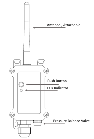
1.6 Button & LEDs
| Behavior on ACT | Function | Action |
|---|---|---|
 1~3s 1~3s | Send an uplink | If sensor has already attached to NB-IoT network, sensor will send an uplink packet, blue led will blink once. |
 >3s >3s | Active Device | Green led will fast blink 5 times, device will enter OTA mode for 3 seconds. And then start to attach NB-IoT network. |
 x5 x5 | Deactivate Device | Red led will solid on for 5 seconds. Means device is in Deep Sleep Mode. |
Note: When the device is executing a program, the buttons may become invalid. It is best to press the buttons after the device has completed the program execution.
1.7 BLE connection
SN50v3-NB support BLE remote configure and firmware update.
BLE can be used to configure the parameter of sensor or see the console output from sensor. BLE will be only activate on below case:
- Press button to send an uplink
- Press button to active device.
- Device Power on or reset.
If there is no activity connection on BLE in 60 seconds, sensor will shut down BLE module to enter low power mode.
1.8 Pin Definitions , Switch & SIM Direction
SN50v3-NB use the mother board which as below.

1.8.1 Jumper JP2
Power on Device when put this jumper.
1.8.2 BOOT MODE / SW1
1) ISP: upgrade mode, device won't have any signal in this mode. but ready for upgrade firmware. LED won't work. Firmware won't run.
2) Flash: work mode, device starts to work and send out console output for further debug
1.8.3 Reset Button
Press to reboot the device.
1.8.4 SIM Card Direction
See this link. How to insert SIM Card.
2. Use SN50v3-NB to communicate with IoT Server
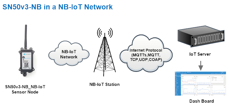
2.1 Send data to IoT server via NB-IoT network
The SN50v3-NB is equipped with a NB-IoT module, the pre-loaded firmware in SN50v3-NB will get environment data from sensors and send the value to local NB-IoT network via the NB-IoT module. The NB-IoT network will forward this value to IoT server via the protocol defined by SN50v3-NB.
Below shows the network structure:
There are two version: -GE and -1T version of SN50v3-NB.
GE Version: This version doesn't include SIM card or point to any IoT server. User needs to use AT Commands to configure below two steps to set SN50v3-NB send data to IoT server.
- Install NB-IoT SIM card and configure APN. See instruction of Attach Network.
- Set up sensor to point to IoT Server. See instruction of Configure to Connect Different Servers.
Below shows result of different server as a glance.
| Servers | Dash Board | Comments |
| Node-Red |
| |
| DataCake |
| |
| Tago.IO |  | |
| General UDP | Raw Payload. Need Developer to design Dash Board | |
| General MQTT | Raw Payload. Need Developer to design Dash Board | |
| ThingSpeak |
| |
| ThingsBoard |
|

1T Version: This version has 1NCE SIM card pre-installed and configure to send value to ThingsEye. User Just need to select the sensor type in ThingsEyeand Activate SN50v3-NB and user will be able to see data in ThingsEye. See here for ThingsEye Config Instruction.
2.2 Working Mode & Uplink Payload
SN50v3-NB has different working mode for the connections of different type of sensors. This section describes these modes. User can use the AT Command AT+CFGMOD to set SN50v3-NB to different working modes.
For example:
AT+CFGMOD=2 // will set the SN50v3-NB to work in MOD=2 distance mode which target to measure distance via Ultrasonic Sensor.
The uplink payloads are composed in ASCII String. For example:
89 30 04 7b 0c e9 17 02 ff ff 00 00 00 0b a4 00 00 66 4f f6 90 (total 24 ASCII Chars). Representative the actually payload:
0x 89 30 04 7b 0c e9 17 02 ff ff 00 00 00 0b a4 00 00 66 4f f6 90 Total 21 bytes
NOTE:
1. All modes share the same Payload Explanation from HERE.
2. By default, the device will send an uplink message every 1 hour.
2.2.1 CFGMOD=1 (Default Mode)
Here is the HEX format of the uplink payload for mode 1:
In this mode, the uplink payload usually contains 37 bytes. (Note: Time stamp field are added since firmware version v1.2.0)

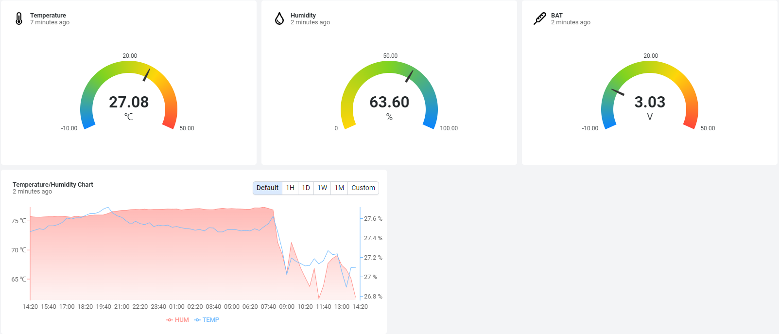
If we use the MQTT client to subscribe to this MQTT topic, we can see the following information when the NB sensor uplink data.
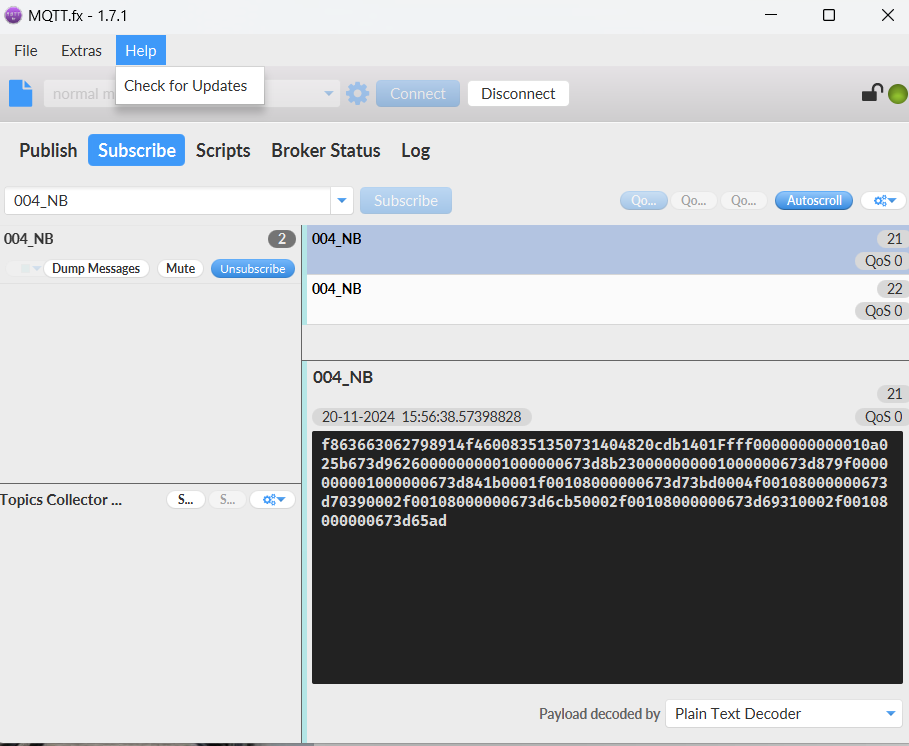
If the payload is: 0xf863663062798914 f460083513507314 0482 0cdb 14 01 00f7 00 00 00 0b94 010c 02db 673d9626
where:
Device ID(f+IMEI): f863663062798914 = 863663062798914
SIM Card ID(f+IMSI): f460083513507314 = 460083513507314
Version: 0x04:SN50v3-NB, 0x82=130=1.3.0
BAT: 0x0cdb = 3291 mV = 3.291V
Singal: 0x14 = 20
Model: 0x01 = 1
Temperature by DS18b20: 0x00f7 = 247/10=24.7
PA4_level: 0x00 =0
Interrupt: 0x00 = 0
Interrupt_level: 0x00 =0
ADC: 0x0b94 =2964= 2964.00mv
Temperature by SHT20/SHT31: 0x010c = 268 = 26.8 °C
Humidity by SHT20/SHT31: 0x02db= 731 = 73.1 %rh
Timestamp: 673D9626 =1732089382= 2024-11-20 15:56:22
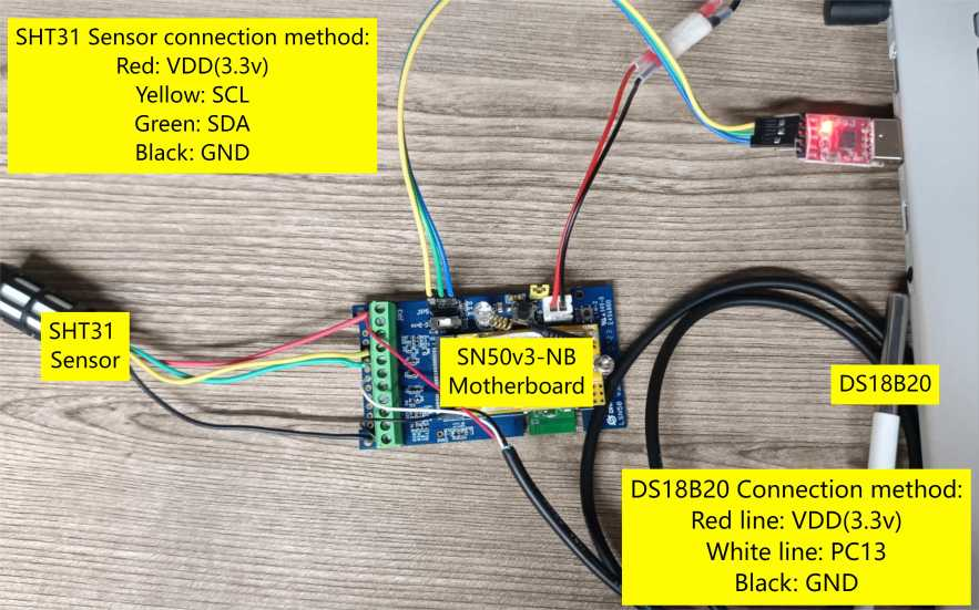
Connection mode of I2C sensor and DS18B20 temperature sensor:
Here is the JSON format of the uplink payload for mode 1:
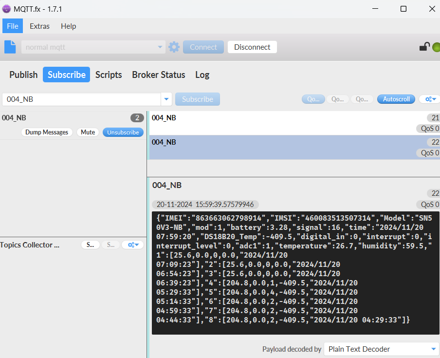
Notice, from above payload:
- Mode, Battery, Signal, time, DS18B20_Temp, Digital_In, Interrupt, Interrupt_Level, adc1, Temperature & Humidity are the value at uplink time.
- Json entry 1 ~ 8 are the last 1 ~ 8 sampling data as specify by AT+CLOCKLOG=1,65535,1,8 Command. Each entry includes (from left to right): Temperature, Humidity, ADC, DS18B20_Temp & Sampling time.
2.2.2 CFGMOD=2 (Distance Mode)
Here is the HEX format of the uplink payload for mode 2:
This mode is target to measure the distance. Total 27 bytes, (Note: Time stamp field are added since firmware version v1.2.0)

If we use the MQTT client to subscribe to this MQTT topic, we can see the following information when the NB sensor uplink data.
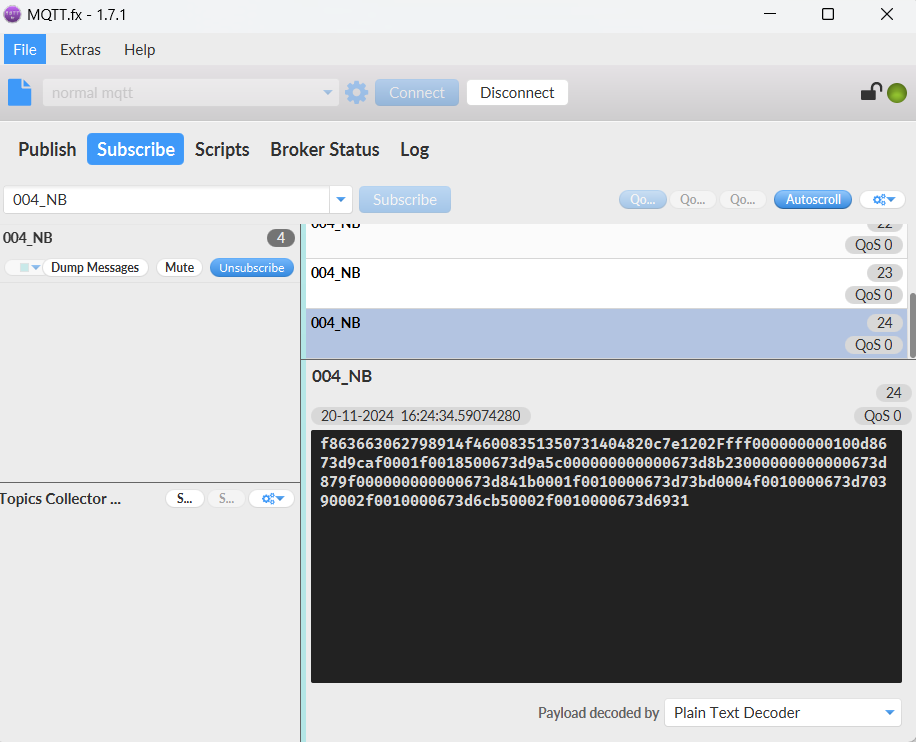
If the payload is 0xf863663062798914 f460083513507314 0482 0c7e 12 02 01b0 00 00 00 0ca8 00d8 673d9caf
where:
Device ID(f+IMEI): f863663062798914 = 863663062798914
SIM Card ID(f+IMSI): f460083513507314 = 460083513507314
Version: 0x04:SN50v3-NB, 0x82=130=1.3.0
BAT: 0x0c7e = 3198mV = 3.198 V
Singal: 0x12 = 18
Model: 0x02 = 2
Temperature by DS18b20: 0x010b= 267 = 26.7 °
PA4_level: 0x00 =0
Interrupt: 0x00 = 0
Interrupt_level: 0x00 =0
ADC: 0x0ca8 = 3240 mv
Distance by LIDAR-Lite V3HP/Ultrasonic Sensor: 0x00d8 = 216 cm
Timestamp: 0x673D9CAF = 1732091055 = 2024-11-20 16:24:15
Connection of LIDAR-Lite V3HP:
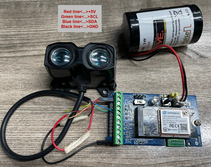
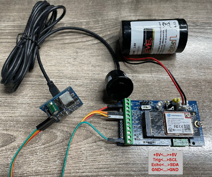
Connection to Ultrasonic Sensor:
Need to remove R1 and R2 resistors to get low power,otherwise there will be 240uA standby current.
Here is the JSON format of the uplink payload for mode 2:
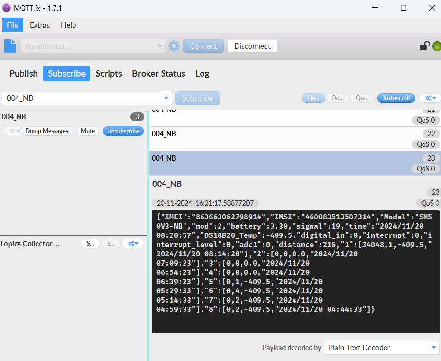
Notice, from above payload:
- Mode, Battery, Signal, time, DS18B20_Temp, Digital_In, Interrupt, Interrupt_Level, adc1, Distance are the value at uplink time.
- Json entry 1 ~ 8 are the last 1 ~ 8 sampling data as specify by AT+CLOCKLOG=1,65535,1,8 Command. Each entry includes (from left to right): Diatance , adc1, DS18B20_Temp& Sampling time.
2.2.3 CFGMOD=3 (3 ADC + I2C)
Here is the HEX format of the uplink payload for mode 3:
This mode has total 31 bytes. Include 3 x ADC + 1x I2C, (Note: Time stamp field are added since firmware version v1.2.0)

ADC1 uses pin PA4 to measure
ADC2 uses pin PA5 to measure
ADC3 uses pin PA8 to measure
(Suitable for motherboard version: LSN50 v3.3)
If we use the MQTT client to subscribe to this MQTT topic, we can see the following information when the NB sensor uplink data.
If the payload is : 0xf863663062798914 f460083513507314 0482 0cd8 0e 03 0b9b 00 00 00 0003 0115 0239 0000 673da2c4
Device ID(f+IMEI): f863663062798914 = 863663062798914
SIM Card ID(f+IMSI): f460083513507314 = 460083513507314
Version: 0x04:SN50v3-NB, 0x82=130=1.3.0
BAT: 0x0cd8 = 3288 mV = 3.288 V
Singal: 0x0e= 14
Model: 0x03 = 3
ADC1: 0x0b9b= 2971mV
PA4_level: 0x00 =0
Interrupt: 0x00 = 0
Interrupt_level: 0x00 =0
ADC2: 0x0003 =3 mv
Temperature by SHT20/SHT31: 0x0115 = 277 = 27.7 °C
Humidity by SHT20/SHT31: 0x0239 =569 = 56.9 %rh
ADC3: 0x0000 = 0 mv
Timestamp: 0x673DA2C4 = 1732092612= 2024-11-20 16:50:12
Here is the JSON format of the uplink payload for mode 3:
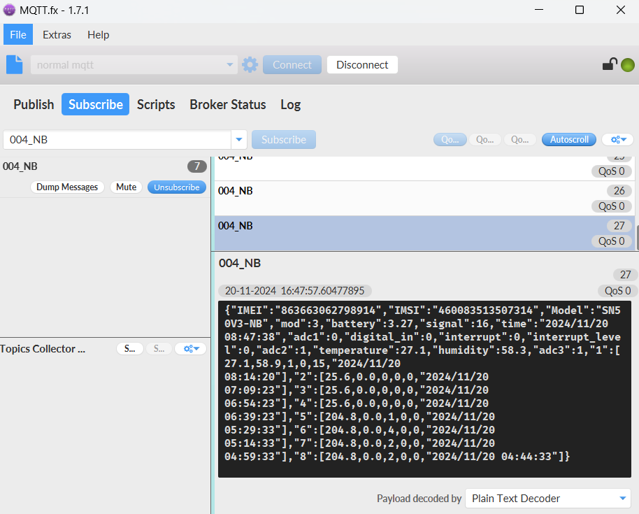
Notice, from above payload:
- Mode, Battery, Signal, time, adc1, Digital_In, Interrupt, Interrupt_Level, adc2, temperature, humidity, adc3 are the value at uplink time.
- Json entry 1 ~ 8 are the last 1 ~ 8 sampling data as specify by AT+CLOCKLOG=1,65535,1,8 Command. Each entry includes (from left to right): temperature, humidity,adc1, adc2, adc3 & Sampling time.
2.2.4 CFGMOD=4 (3 x DS18B20)
Here is the HEX format of the uplink payload for mode 4:
Hardware connection is as below.
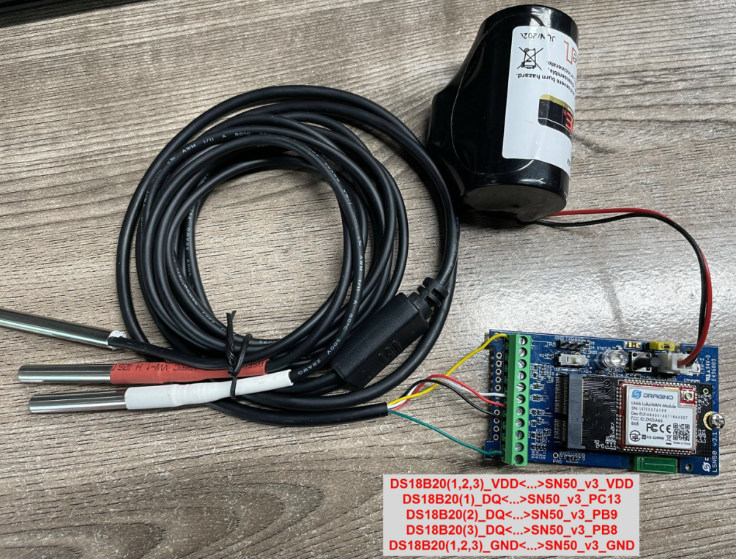
This mode has total 37 bytes As shown below: (Note: Time stamp field are added since firmware version v1.2.0)

Temperature1 uses pin PC13 to measure
Temperature2 uses pin PA9 to measure
Temperature3 uses pin PB8 to measure
(Suitable for motherboard version: LSN50 v3.3)
If we use the MQTT client to subscribe to this MQTT topic, we can see the following information when the NB sensor uplink data.
If the payload is 0x f863663062798914 f460083513507314 0482 0cd6 11 04 0102 0003 00 00 00 0100 0102 673dade5
where:
Device ID(f+IMEI): f863663062798914 = 863663062798914
SIM Card ID(f+IMSI): f460083513507314 = 460083513507314
Version: 0x04:SN50v3-NB, 0x82=130=1.3.0
BAT: 0x0cd6 = 3286 mV = 3.286 V
Singal: 0x11 = 17
Model: 0x04 = 4
Temperature1 by DS18b20: 0x0102 = 258 = 25.8 °C
ADC: 0x0003 = 3 mv
PA4_level: 0x00 =0
Interrupt: 0x00 = 0
Interrupt_level: 0x00 =0
Temperature2 by DS18b20: 0x0100 = 256 = 25.6°C
Temperature3 by DS18b20: 0x0102 = 258 = 25.8 °C
Timestamp: 0x673DADE5 = 1732095461= 2024-11-20 17:37:41
Here is the JSON format of the uplink payload for mode 4:

Notice, from above payload:
- Mode, Battery, Signal, time, DS18B20_Temp, adc1, Digital_In, Interrupt, Interrupt_Level, DS18B20_Temp2, DS18B20_Temp3 are the value at uplink time.
- Json entry 1 ~ 8 are the last 1 ~ 8 sampling data as specify by AT+CLOCKLOG=1,65535,1,8 Command. Each entry includes (from left to right): ADC, DS18B20_Temp, DS18B20_Temp2, DS18B20_Temp3 & Sampling time.
2.2.5 CFGMOD=5 (Weight Measurement by HX711)
Here is the HEX format of the uplink payload for mode 5:
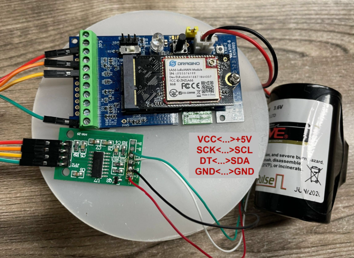
Notes about hardware connection:
- Don't connect the HX711 module VCC to SN50v3-NB 3.3v VCC, in this case, the SN50v3-NB will always power on HX711 and the battery will run out soon.
- HX711 support 5v VCC, but while connect the SN50v3-NB's +5V to HX711 VCC, the value from HX711 is not stable.
- Connect SN50v3-NB +5V to HX711 VCC via a LDO module is stable.
Each HX711 need to be calibrated before used. User need to do below two steps:
- Zero calibration. Don't put anything on load cell and run AT+WEIGRE to calibrate to Zero gram.
- Adjust calibration factor (default value 400): Put a known weight thing on load cell and run AT+WEIGAP to adjust the Calibration Factor.
For example:
AT+WEIGAP =403.0
Response: Weight is 401 g
Check the response of this command and adjust the value to match the real value for thing.
This mode has total 35 bytes As shown below: (Note: Time stamp field are added since firmware version v1.2.0).

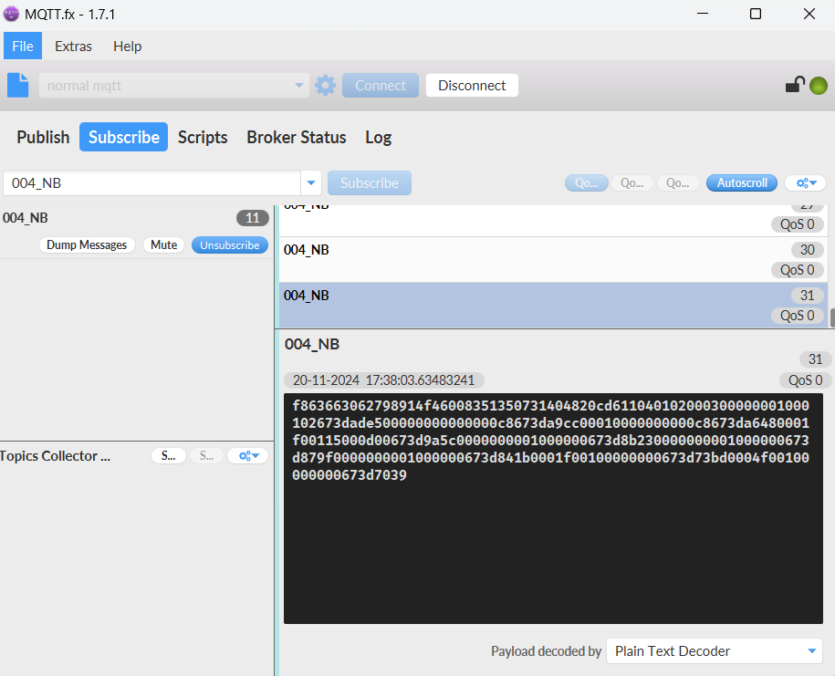
If we use the MQTT client to subscribe to this MQTT topic, we can see the following information when the NB sensor uplink data.
If the payload is 0x f863663062798914 f460083513507314 0482 0cce 15 05 0137 0b97 00 00 00 00f5 673e9440
where:
Device ID(f+IMEI): f863663062798914 = 863663062798914
SIM Card ID(f+IMSI): f460083513507314 = 460083513507314
Version: 0x04:SN50v3-NB, 0x82=130=1.3.0
BAT: 0x0cce = 3278mV = 3.278 V
Singal: 0x15 = 21
Model: 0x05 = 5
Temperature by DS18b20: 0x0137 = 311 = 31.1 °C
ADC: 0x0b97 = 2967 mv
PA4_level: 0x00 =0
Interrupt: 0x00 = 0
Interrupt_level: 0x00 =0
Weigt by HX711: 0x00f5 = 245 g
Timestamp: 0x673E9440 = 1732154432 = 2024-11-21 10:00:32
Here is the JSON format of the uplink payload for mode 5:
Notice, from above payload:
- Mode, Battery, Signal, time, DS18B20_Temp, adc1, Digital_In, Interrupt, Interrupt_Level, weight are the value at uplink time.
- Json entry 1 ~ 8 are the last 1 ~ 8 sampling data as specify by AT+CLOCKLOG=1,65535,1,8 Command. Each entry includes (from left to right): adc1, DS18B20_Temp, weight & Sampling time.
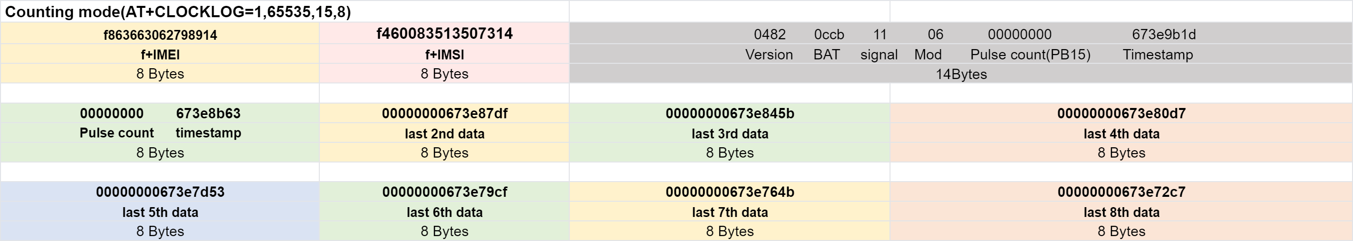
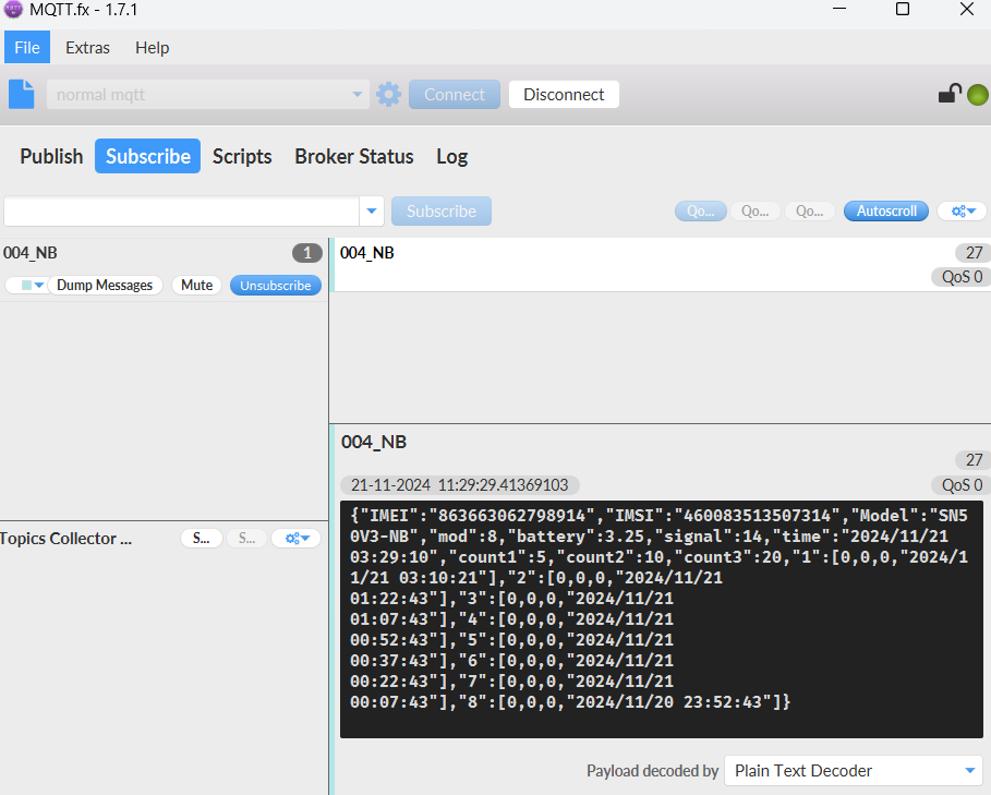
2.2.6 CFGMOD=6 (Counting mode)
Here is the HEX format of the uplink payload for mode 6:
In this mode, uplink payload includes in total 30 bytes, (Note: Time stamp field are added since firmware version v1.2.0)
If we use the MQTT client to subscribe to this MQTT topic, we can see the following information when the NB sensor uplink data.
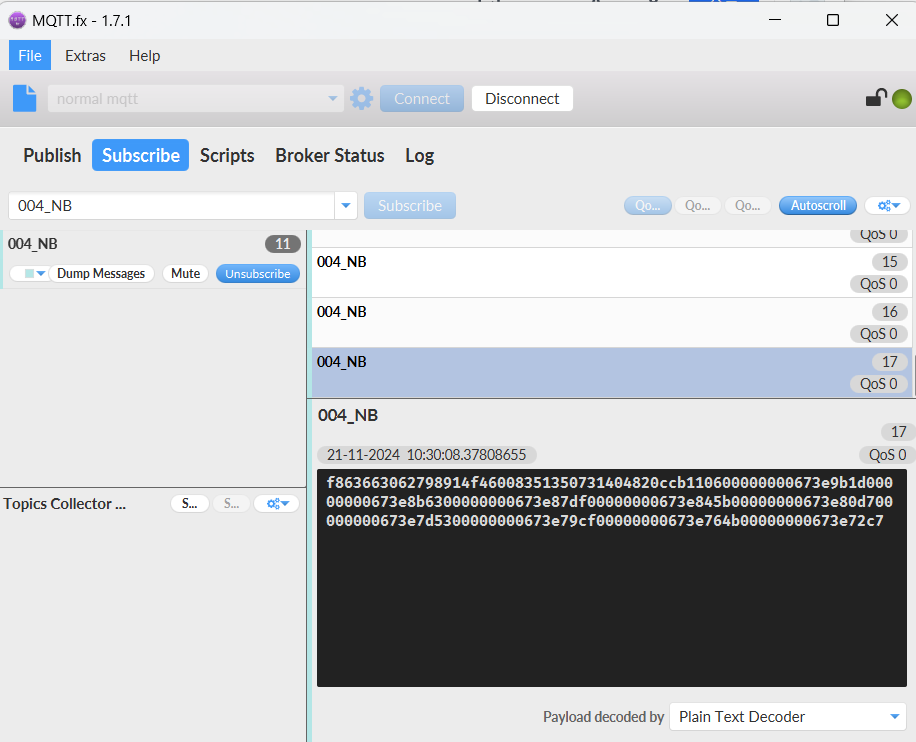
The payload is ASCII string, representative same HEX: 0x f863663062798914 f460083513507314 0482 0ccb 11 06 00000000 673e9b1d
where:
Device ID(f+IMEI): f863663062798914 = 863663062798914
SIM Card ID(f+IMSI): f460083513507314 = 460083513507314
Version: 0x04: SN50v3-NB, 0x82=130=1.3.0
BAT: 0x0ccb =3275mV =3.275V
Singal: 0x11 = 17
Model: 0x06 = 6
Pulse count: 0x00000000= 0
Timestamp: 0x673E9B1D = 1732156189= 2024-11-21 10:29:49
Here is the JSON format of the uplink payload for mode 6:
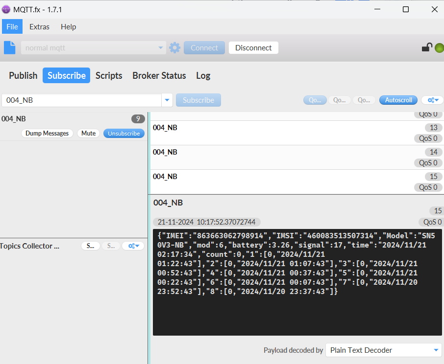
Notice, from above payload:
- Mode, Battery, Signal, time, count are the value at uplink time.
- Json entry 1 ~ 8 are the last 1 ~ 8 sampling data as specify by AT+CLOCKLOG=1,65535,1,8 Command. Each entry includes (from left to right): Count & Sampling time.
2.2.7 CFGMOD=7 (3xADC + 3xDS18B20 mode)
Here is the HEX format of the uplink payload for mode 7:
In this mode, the uplink payload totals 169 bytes, including 41 bytes of real-time data and 16 bytes of timed acquisition data (8 groups are stored by default) (Note: Added since firmware version v1.2.4)
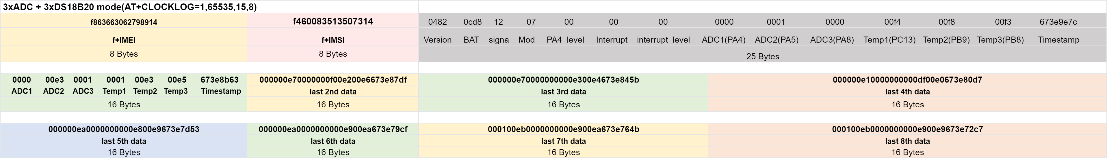
ADC1 uses pin PA4 to measure
ADC2 uses pin PA5 to measure
ADC3 uses pin PA8 to measure
(Suitable for motherboard version: LSN50 v3.3)
If we use the MQTT client to subscribe to this MQTT topic, we can see the following information when the NB sensor uplink data.
If payload is: 0x f863663062798914 f460083513507314 0482 0cd8 12 07 00 00 00 0000 00eb 023c 00f4 00f8 00f3 673e9e7c
Device ID(f+IMEI): f863663062798914 = 863663062798914
SIM Card ID(f+IMSI): f460083513507314 = 460083513507314
Version: 0x04: SN50v3-NB, 0x82=130=1.3.0
BAT: 0x0cd8 = 3288 mV = 3.288 V
Singal: 0x12 =18
Model: 0x07 = 7
PA4_level: 0x00 =0
Interrupt: 0x00 = 0
Interrupt_level: 0x00 =0
ADC1(PA4): 0x0000 = 0mV
ADC2(PA5): 0x00eb = 235mV
ADC3(PA8): 0x023c = 572mV
Temp1(PC13): 0x00f4 = 244/10 = 24.4℃
Temp2(PB9): 0x00f8 = 248/10 = 24.8℃
Temp3(PB8): 0x00f3 = 243/10 = 24.3℃
Timestamp: 0x673E9E7C = 1732157052 = 2024-11-21 10:44:12
Here is the JSON format of the uplink payload for mode 7:

Notice, from above payload:
- Mode, Battery, Signal, time, Digital_In, Interrupt, Interrupt_Level, adc1, adc2, adc3, DS18B20_Temp, DS18B20_Temp2, DS18B20_Temp3 are the value at uplink time.
- Json entry 1 ~ 8 are the last 1 ~ 8 sampling data as specify by AT+CLOCKLOG=1,65535,1,8 Command. Each entry includes (from left to right): adc2, adc3, DS18B20_Temp, DS18B20_Temp2, DS18B20_Temp3 & Sampling time.
2.2.8 CFGMOD=8 (Three interrupts or three counting modes)
Here is the HEX format of the uplink payload for mode 8(a):
2.2.8.a Three interrupts modes:
In this mode, the uplink payload totals 132 bytes, including 36 bytes of real-time data and 12 bytes of timed acquisition data (8 groups are stored by default). (Note: Added since firmware version v1.2.4)

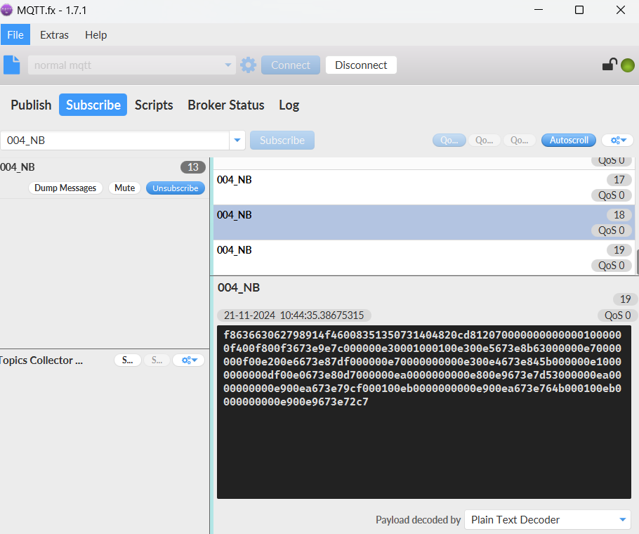
If we use the MQTT client to subscribe to this MQTT topic, we can see the following information when the NB sensor uplink data.

If payload is: 0x f863663062798914 f460083513507314 0482 0cc3 11 08 0b9d 0102 00 00 01 01 00 00 673ea638
Device ID(f+IMEI): f863663062798914 = 863663062798914
SIM Card ID(f+IMSI): f460083513507314 = 460083513507314
Version: 0x04: SN50v3-NB, 0x82=130=1.3.0
BAT: 0x0cc3 = 3267 mV = 3.267 V
Singal: 0x11 = 17
Model: 0x08 = 8
ADC2(PA5): 0x0b9d = 2973mv
DS18B20_temp(PC13): 0x0102 = 258/10 = 25.8℃
Interrupt(PB15): 0x00 = 0
Interrupt_level(PB15): 0x00 = 0
Interrupt_pa4(PA4): 0x01 = 1 ,The uplink is triggered by an interrupt of the PA4 pin.
Interrupt_level_pa4(PA4): 0x01 = 1 ,The PA4 pin is triggered by a high level.
Interrupt_pa8(PA8): 0x00 = 0
Interrupt_level_pa8(PA8): 0x00 = 0
Timestamp: 0x673EA638 = 1732159032 = 2024-11-21 11:17:12
Here is the JSON format of the uplink payload for mode 8(a):
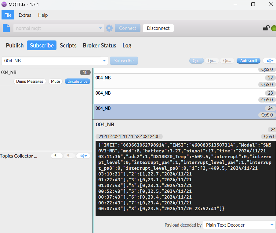
Notice, from above payload:
- Mode, Battery, Signal, Time, adc2(PA5), DS18B20_Temp, Interrupt(PB15), Interrupt_Level(PB15), interrupt_pa4, interrupt_level_pa4, interrupt_pa8, interrupt_level_pa8 are the value at uplink time.
- Json entry 1 ~ 8 are the last 1 ~ 8 sampling data as specify by AT+CLOCKLOG=1,65535,1,8 Command. Each entry includes (from left to right): adc2, DS18B20_Temp & Sampling time.
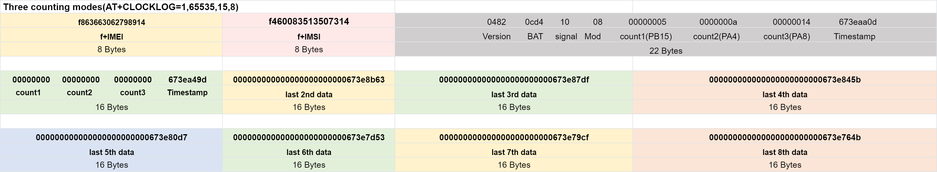
2.2.8.b Three counting modes:
Here is the HEX format of the uplink payload for mode 8(b):
In this mode, the uplink payload totals 166 bytes, including 38 bytes of real-time data and 16 bytes of timed acquisition data (8 groups are stored by default). (Note: Added since firmware version v1.2.4)
If we use the MQTT client to subscribe to this MQTT topic, we can see the following information when the NB sensor uplink data.
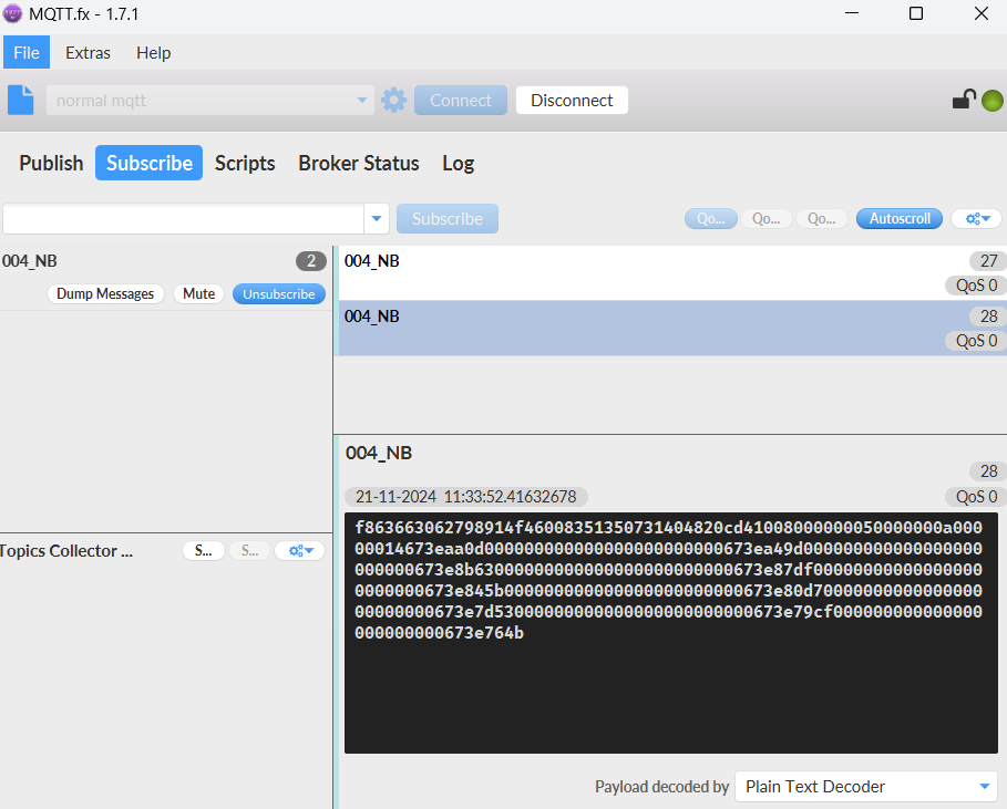
If payload is : 0x f863663062798914 f460083513507314 0482 0cd4 10 08 00000005 0000000a 00000014 673eaa0d
Device ID(f+IMEI): f863663062798914 = 863663062798914
SIM Card ID(f+IMSI): f460083513507314 = 460083513507314
Version: 0x04: SN50v3-NB, 0x82=130=1.3.0
BAT: 0x0cd4 = 3284 mV = 3.284 V
Singal: 0x10 = 16
Model: 0x08 = 8
count1(PB15): 0x00000005 = 5
count2(PA4): 0x0000000a = 10
count3(PA8): 0x00000014 = 20
Timestamp: 0x673EAA0D = 1732160013 = 2024-08-31 13:37:40
Here is the JSON format of the uplink payload for mode 8(b):
Notice, from above payload:
- Mode, Battery, Signal, time, count1, count2, count3 are the value at uplink time.
- Json entry 1 ~ 8 are the last 1 ~ 8 sampling data as specify by AT+CLOCKLOG=1,65535,1,8 Command. Each entry includes (from left to right): count1, count2, count3 & Sampling time.
2.2.9 CFGMOD=9 (Count+SHT31 mode)
Here is the HEX format of the uplink payload for mode 9:
In this mode, the uplink payload totals 131 bytes, including 35 bytes of real-time data and 12 bytes of timed acquisition data (8 groups are stored by default)(Note: Added since firmware version v1.2.4)

If we use the MQTT client to subscribe to this MQTT topic, we can see the following information when the NB sensor uplink data.

If payload is: 0x f863663062798914 f460083513507314 0482 0cc9 11 09 00 0000001b 010d 022c 673eacca
Device ID(f+IMEI): f863663062798914 = 863663062798914
SIM Card ID(f+IMSI): f460083513507314 = 460083513507314
Version: 0x04: SN50v3-NB, 0x82=130=1.3.0
BAT: 0x0cc9 = 3273 mV = 3.273 V
Singal: 0x11 = 17
Model: 0x09 = 9
digital in: 0x00 = 0( 0:low level; 1:high level)
count(PA8): 0x0000001b = 27
Temp(sht31): 0x010d = 269/10 = 26.9℃
Hum(sht31): 0x022c = 556/10 = 55.6%rh
Timestamp: 0x673EACCA = 1732160714 = 2024-11-21 11:45:14

Here is the JSON format of the uplink payload for mode 9:
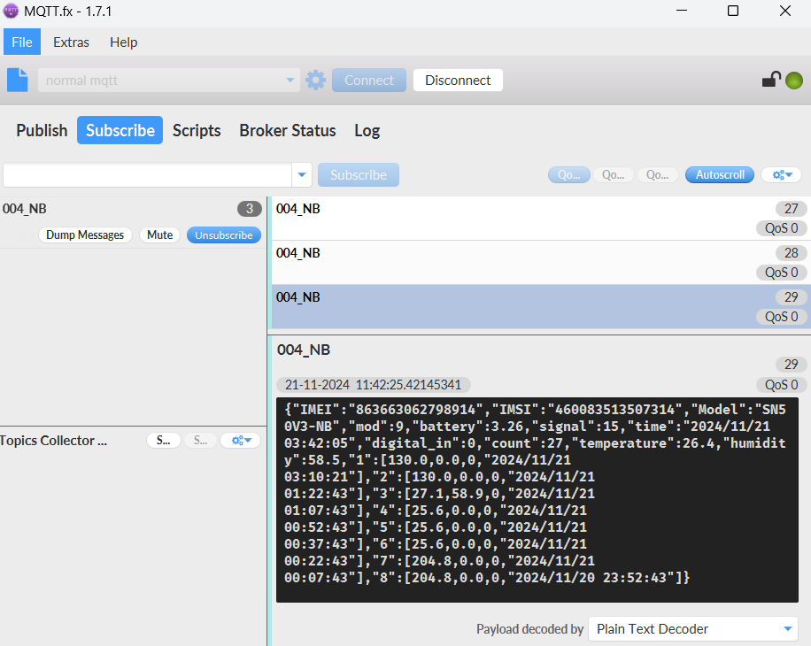
Notice, from above payload:
- Mode, Battery, Signal, time, digital_in, count, temperature, humidity are the value at uplink time.
- Json entry 1 ~ 8 are the last 1 ~ 8 sampling data as specify by AT+CLOCKLOG=1,65535,1,8 Command. Each entry includes (from left to right): temperature, humidity, count & Sampling time.
2.2.10 CFGMOD=10 (TMP117 Temperature Sensor Mode)
Here is the HEX format of the uplink payload for mode 10:
In this mode, the uplink payload totals 114 bytes, including 34 bytes of real-time data and 10 bytes of timed acquisition data (8 groups are stored by default)(Note: Added since firmware version v1.2.4)

If we use the MQTT client to subscribe to this MQTT topic, we can see the following information when the NB sensor uplink data.
If payload is: 0x f863663062798914 f460083513507314 0482 0cdd 10 0a 010e 0000 00 00 0a01 673eaf5c
Device ID(f+IMEI): f863663062798914 = 863663062798914
SIM Card ID(f+IMSI): f460083513507314 = 460083513507314
Version: 0x04: SN50v3-NB, 0x82=130=1.3.0
BAT: 0x0cdd = 3293 mV = 3.293 V
Singal: 0x10 = 16
Model: 0x0a = 10
DS18B20: 0x010e = 270/10 = 27.0℃
ADC1(PA4): 0x0000 = 0mV
Interrupt: 0x00 = 0
Interrupt_level: 0x00 =0
Temp(TMP117): 0x0a01 = 2561/100 = 25.61℃
Timestamp: 0x673EAF5C = 1732161372 = 2024-11-21 11:56:12

Here is the JSON format of the uplink payload for mode 10:
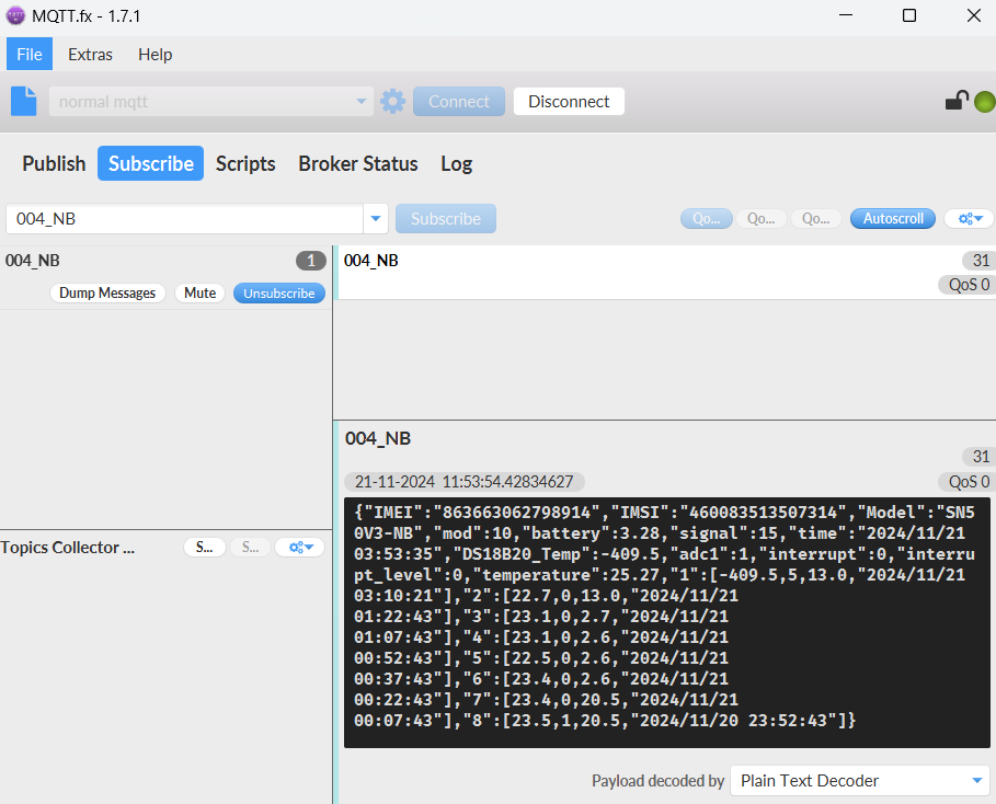
Notice, from above payload:
- Mode, Battery, Signal, time, DS18B20_Temp, adc1, interrupt, interrupt_level, temperature(TEM117) are the value at uplink time.
- Json entry 1 ~ 8 are the last 1 ~ 8 sampling data as specify by AT+CLOCKLOG=1,65535,1,8 Command. Each entry includes (from left to right): DS18B20_Temp, adc1, temperature(TEM117) & Sampling time.
2.3 Payload Types
To meet different server requirement, SN50v3-NB supports different payload type.
Includes:
- General JSON format payload. (Type=5)
- HEX format Payload. (Type=0)
- ThingSpeak Format. (Type=1)
- ThingsBoard Format. (Type=3)
User can specify the payload type when choose the connection protocol. Example:
AT+PRO=1,0 // Use COAP Connection & hex Payload
AT+PRO=1,5 // Use COAP Connection & Json Payload
AT+PRO=2,0 // Use UDP Connection & hex Payload
AT+PRO=2,5 // Use UDP Connection & Json Payload
AT+PRO=3,0 // Use MQTT Connection & Json Payload
AT+PRO=3,5 // Use MQTT Connection & Json Payload
AT+PRO=4,0 // Use TCP Connection & Json Payload
AT+PRO=4,5 // Use TCP Connection & Json Payload
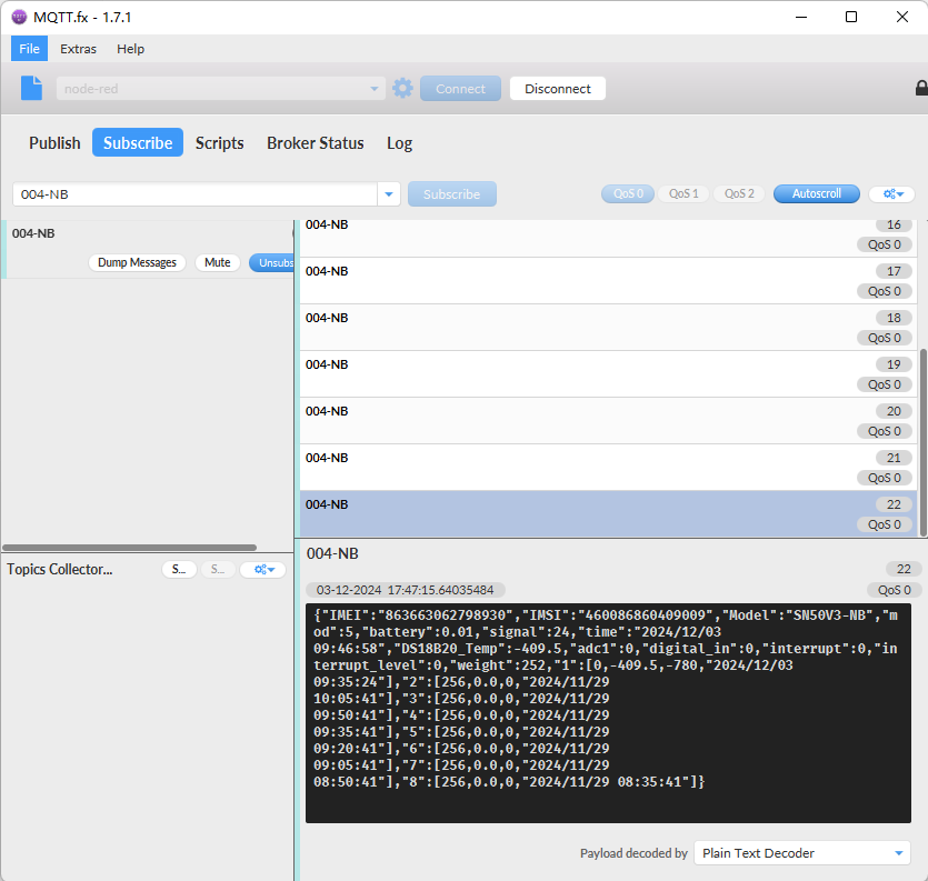
2.3.1 General Json Format(Type=5)
This is the General Json Format. As below:
{"IMEI":"863663062798930","Model":"SN50V3-NB","mod":1,"battery":3.36,"signal":19,"DS18B20_Temp":-409.5,"digital_in":0,"interrupt":0,"interrupt_level":0,"adc1":2974,"temperature":26.9,"humidity":73.9,"1":[130.0,0.0,0,-409.5,"2024/05/24 01:20:14"],"2":[24.0,64.1,1,-409.5,"2024/05/24 00:53:05"],"3":[23.9,64.1,1,-409.5,"2024/05/24 00:38:05"],"4":[23.8,64.0,1,-409.5,"2024/05/24 00:23:05"],"5":[24.2,63.7,1,-409.5,"2024/05/24 00:08:05"],"6":[24.3,63.5,0,-409.5,"2024/05/23 23:53:05"],"7":[24.7,64.3,0,-409.5,"2024/05/23 23:38:05"],"8":[24.5,69.4,1,-409.5,"2024/05/23 23:23:05"]}
Notice, from above payload:
- Temperature , Humidity , Battery & Signal are the value at uplink time.
- Json entry 1 ~ 8 are the last 1 ~ 8 sampling data as specify by AT+CLOCKLOG=1,65535,15,8 Command. Each entry includes (from left to right): Temperature, Humidity, Sampling time.
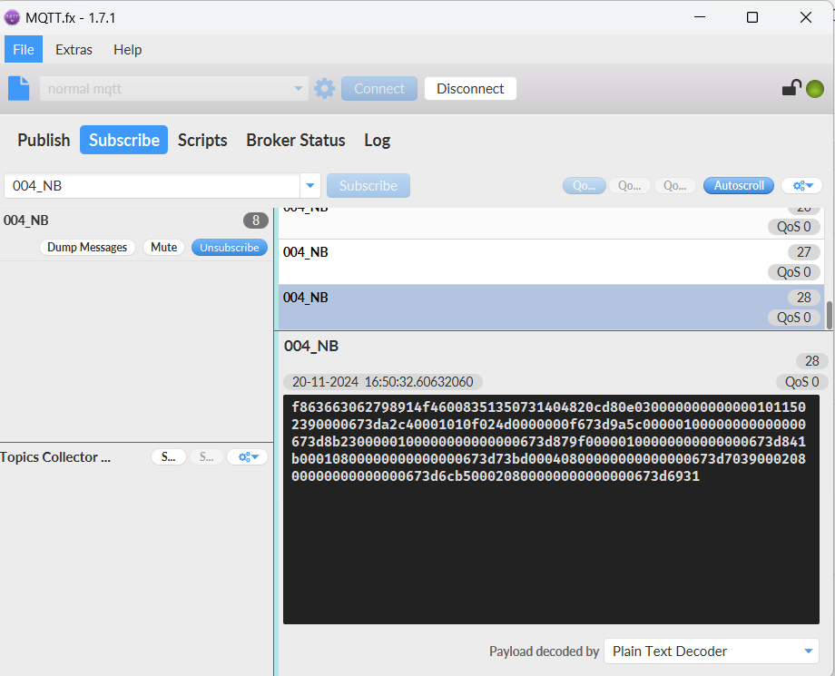
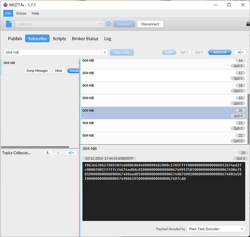
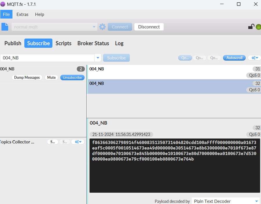
2.3.2 HEX format Payload(Type=0)
This is the HEX Format. As below:
f863663062798914f46008351350731404820cdb1401Ffff0000000000010a025b673d96260000000001000000673d8b230000000001000000673d879f0000000001000000673d841b0001f00108000000673d73bd0004f00108000000673d70390002f00108000000673d6cb50002f00108000000673d69310002f00108000000673d65ad

Note: Only hex payload contains PA4_level bytes, JSON payload does not contain PA4_level.
f+IMEI:
Ex1:0xf863663062798914 = 863663062798914
f+IMSI:
Ex1: f460083513507314 = 460083513507314
Version:
These bytes include the hardware and software version.
Higher byte: Specify Sensor Model: 0x04 for SN50v3
Lower byte: Specify the software version: 0x82=130, means firmware version 1.3.0
BAT (Battery Info):
Ex1: 0x0cdb = 3291mV
Signal Strength:
NB-IoT Network signal Strength.
Ex1: 0x13 = 19
0 -113dBm or less
1 -111dBm
2...30 -109dBm... -53dBm
31 -51dBm or greater
99 Not known or not detectable
Temperature:
If payload is: 010aH: (0105 & 8000 == 0), temp = 0106H /10 = 26.6 degree
If payload is: FF3FH : (FF3F & 8000 == 1) , temp = (FF3FH - 65536)/10 = -19.3 degrees.
(FF3F & 8000: Judge whether the highest bit is 1, when the highest bit is 1, it is negative)
Humidity:
Read:025b(H)=603(D) Value: 603 / 10=60.3, So 60.3%
TimeStamp:
Unit TimeStamp Example: 673d9626(H) = 1732089382(D)
Put the decimal value into this link(https://www.epochconverter.com/https://www.epochconverter.com/) to get the time.
2.3.3 ThingsBoard Payload(Type=3)
Type3 payload special design for ThingsBoard, it will also configure other default server to ThingsBoard.
{
"topic": "004-NB",
"payload": {
"IMEI": "863663062765285",
"IMSI": "460086859301439",
"Model": "SN50V3-NB",
"mod": 1,
"battery": 3.37,
"signal": 22,
"time": "2024/12/07 01:07:05",
"DS18B20_Temp": -409.5,
"digital_in": 0,
"interrupt": 0,
"interrupt_level": 0,
"adc1": 1,
"temperature": 23.1,
"humidity": 52.0,
"1": [7.8, 1141.6, 26449, 3171.9, "1970/03/01 07:07:05"],
"2": [0.0, 0.0, 26449, 3081.9, "1970/07/14 04:20:16"],
"3": [7.8, 1141.6, 26449, 2991.9, "1970/03/01 07:07:05"],
"4": [0.0, 0.0, 26449, 2901.9, "1970/07/14 04:20:16"],
"5": [7.8, 1141.6, 26449, 2811.9, "1970/03/01 07:07:05"],
"6": [0.0, 0.0, 26449, 2721.9, "1970/07/14 04:20:16"],
"7": [7.8, 1141.6, 26449, 2631.9, "1970/03/01 07:07:05"],
"8": [0.0, 0.0, 26449, 2541.9, "1970/07/14 04:20:16"]
}
}

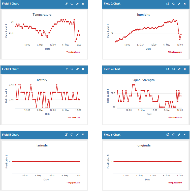
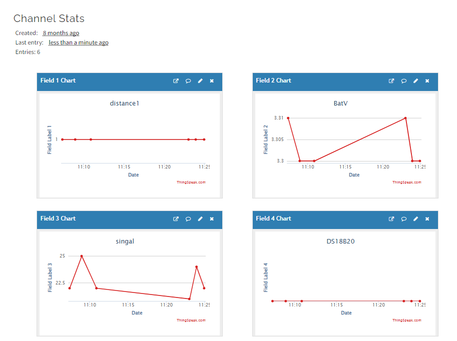
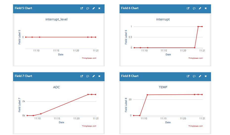
2.3.4 ThingSpeak Payload(Type=1)
This payload meets ThingSpeak platform requirement. It includes only four fields. Form 1~8 are:
distance1, Battery, Signal, DS18B20_Temp, Interrupt_level, Interrupt, ADC,Temperature. This payload type only valid for ThingSpeak Platform.
Note: ThingSpeak has a maximum of eight fields, so the humidity curve is not on the graph.
As below:
field1=distance1 value&field2=battery value&field3=Signal value&field4=DS18B20_Temp value&field5=Interrupt_level value&field6=ADC value&field7=Temperature value&field8=Humidity value
2.4 Test Uplink and Change Update Interval
By default, Sensor will send uplinks every 2 hours
User can use below commands to change the uplink interval.
AT Command: AT+TDC
Example: AT+TDC=7200 // Set Update Interval to 7200 seconds
Downlink Command: 0x01
Format: Command Code (0x01) followed by 3 bytes.
Example: 12 hours= 43200 seconds 43200(D)=0xA8C0(H)
Downlink Payload: 01 00 A8 C0 // AT+TDC=43200, Set Update Interval to 12 hours.
Note: User can also push the button for more than 1 second to activate an uplink.
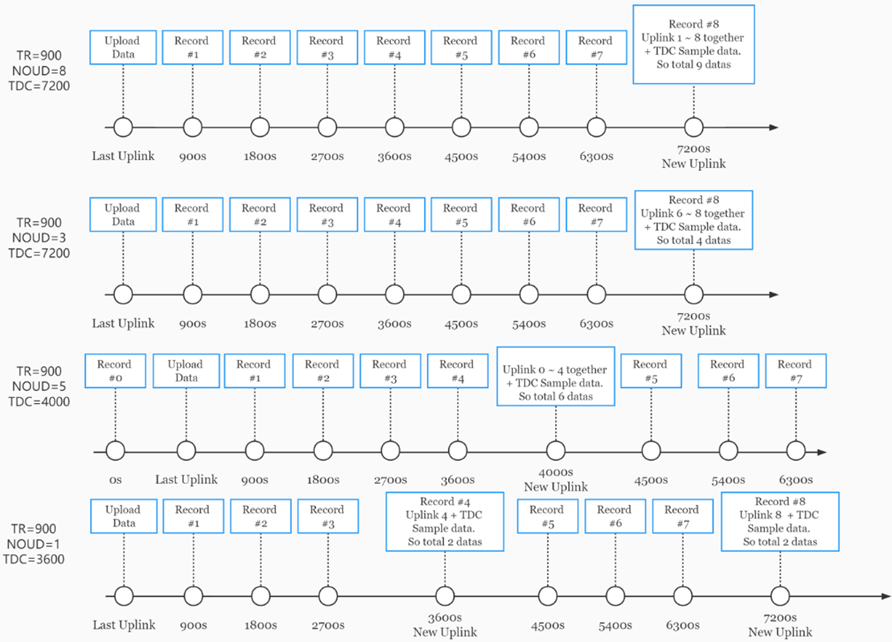
2.5 Multi-Samplings and One uplink
Notice: The AT+NOUD feature is upgraded to Clock Logging, please refer Clock Logging Feature.
To save battery life, SN50v3-NB will sample temperature & humidity data every 15 minutes and send one uplink every 2 hours. So each uplink it will include 8 stored data + 1 real-time data. They are defined by:
- AT+TR=900 // The unit is seconds, and the default is to record data once every 900 seconds (15 minutes, the minimum can be set to 180 seconds)
- AT+NOUD=8 // The device uploads 8 sets of recorded data by default. Up to 32 sets of record data can be uploaded.
The diagram below explains the relationship between TR, NOUD, and TDC more clearly:
2.6 Trggier an uplink by external interrupt
Feature, Set Interrupt mode for PB15,PA4,PA8.
AT command:AT+INTMOD
| Command Example | Function | Response |
|---|---|---|
| AT+INTMOD? | Get or Set the trigger interrupt mode | 1:0,2:0,3:0(default) |
| AT+INTMOD=? | Get current trigger mode 0:input 1:falling or rising 2:falling 3:rising | 1:1,2:1,3:1 OK
|
| AT+INTMOD=a,b,c | Parameter a sets the PB15 interrupt triggering mode, parameter b sets the PA4 interrupt triggering mode, and parameter c sets the PA8 interrupt triggering mode. | OK |
Example:
- AT+INTMOD=1,0,2 // Set the PB15 interrupt to be triggered by a rising or falling edge; set the PA4 interrupt function off and PA4 as a signal input pin; set the PA8 interrupt to be triggered by a falling edge.
- AT+INTMOD=0,1,3 // Set the PB15 interrupt function off and PB15 as a signal input pin; set the PA4 interrupt to be triggered by a rising or falling edge; set the PA8 interrupt to be triggered by a rising edge.
Downlink command: 0x06
Format: Command Code (0x06) followed by 3 byte.
Ex1: Downlink payload: 0x06010002 // Equal to AT+INTMOD=1,0,2
Ex2: Downlink payload: 0x06000103 // Equal to AT+INTMOD=0,1,3
2.7 +5V Output
Control the output duration 5V . Before each sampling, device will
1. first enable the power output to external sensor,
2. keep it on as per duration, read sensor value and construct uplink payload
3. final, close the power output.
AT command: AT+5VT
| Command Example | Function | Response |
|---|---|---|
| AT+5VT=? | Show 5V open time. | 0(default) |
| AT+5VT=1000 | Close after a delay of 1000 milliseconds. | OK |
2.8 Analogue Digital Converter (ADC)
The ADC pins in SN50V3-NB can measure range from 0~Vbat, it use reference voltage from STM32. If user need to measure a voltage > VBat, please use resistors to divide this voltage to lower than VBat, otherwise, it may destroy the ADC pin.
Note: minimum VBat is 2.5v, when batrrey lower than this value. Device won't be able to send LoRa Uplink.
The ADC monitors the voltage on the PA0 line, in mV.
Ex: 0x021F = 543mv,
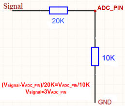
Note: If the ADC type sensor needs to be powered by SN50_v3, it is recommended to use +5V to control its switch.Only sensors with low power consumption can be powered with VDD.
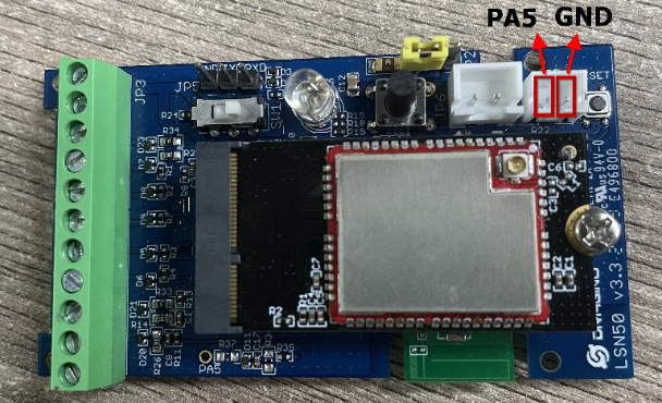
The position of PA5 on the hardware after SN50 v3.3 is changed to the position shown in the figure below, and the collected voltage becomes one-sixth of the original.
2.9 Clock logging (Since firmware version v1.2.1)
Sometimes when we deploy lots of end nodes in field. We want all sensors sample data at the same time, and upload these data together for analyze. In such case, we can use clock loging feature.
We can use this command to set the start time of data recording and the time interval to meet the requirements of the specific collection time of data.
- AT command: AT+CLOCKLOG=a,b,c,d
a: 0: Disable Clock logging. 1: Enable Clock Logging
b: Specify First sampling start second: range (0 ~ 3599, 65535) // Note: If parameter b is set to 65535, the log period starts after the node accesses the network and sends packets.
c: Specify the sampling interval: range (0 ~ 255 minutes)
d: How many entries should be uplink on every TDC (max 32)
Note: To disable clock recording, set the following parameters: AT+CLOCKLOG=1,65535,0,0
Example:
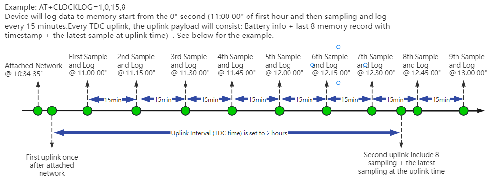
AT+CLOCKLOG=1,65535,1,5
After the node sends the first packet, data is recorded to the memory at intervals of 1 minute. For each TDC uplink, the uplink load will include: battery information + the last 5 memory records (payload + timestamp).

Note: Users need to synchronize the server time before configuring this command. If the server time is not synchronized before this command is configured, the command takes effect only after the node is reset.
- Downlink command: 0x0A
Format: Command Code (0x0A) followed by 5 bytes.
- Example 1: Downlink Payload: 0A01FFFF0F08 // Set SHT record time: AT+CLOCKLOG=1,65535,15,8
- Example 1: Downlink Payload: 0A0104B00F08 // Set SHT record time: AT+CLOCKLOG=1,1200,15,8
Note: When entering the downlink payload, there must be no Spaces between bytes.
2.10 Example Query saved historical records
- AT command: AT+CDP
This command can be used to search the saved history, recording up to 32 groups of data, each group of historical data contains a maximum of 100 bytes.

2.11 Uplink log query
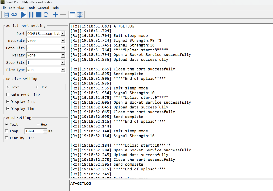
- AT command: AT+GETLOG
This command can be used to query upstream logs of data packets.
2.12 Scheduled domain name resolution
This command is used to set up scheduled domain name resolution.
AT command:
- AT+DNSTIMER // Unit: hour
After setting this command, domain name resolution will be performed regularly.
2.13 Set the QoS level
This command is used to set the QoS level of MQTT.
AT command:
- AT+MQOS // 0~2
Downlink command: 0x07
Format: Command Code (0x07) followed by 1 byte.
Ex1: Downlink payload: 0x0700 //AT+MQOS=0
Ex2: Downlink payload: 0x0701 //AT+MQOS=1
2.14 Set CoAP option
This command sets the connection parameters of the COAP.
AT command:
- AT+URI1 // CoAP option name, CoAP option length, "CoAP option value"
- AT+URI2 // CoAP option name, CoAP option length, "CoAP option value"
- AT+URI3 // CoAP option name, CoAP option length, "CoAP option value"
- AT+URI4 // CoAP option name, CoAP option length, "CoAP option value"
Example:
- AT+URI1=11,38,"i/faaa241f-af4a-b780-4468-c671bb574858"
2.15 Get or Set Count value
Feature,Get or set the count value and set the interrupt mode or count mode.(Note: Added since firmware version v1.2.4)
AT command:AT+EXT
| Command Example | Function | Response |
|---|---|---|
| AT+EXT? | Get or Set Count value | OK |
| AT+EXT=? | Get count value and current mode The last parameter: 0: interrupt trigger mode; 1: count mode. | 1:108,2:92,3:78,1 OK |
| AT+EXT=0,0,0,1 | Set PB15,PA4, PA8 to count mode and count value to 0. | OK |
Note:
- There is no downlink command for this instruction, it can only be set through the serial port.
- The format of AT instruction is: AT+EXT=0,0,0,1 or AT+EXT=0,0,0,0
- The last parameter of the current instruction sets the pin's operating mode to interrupt-triggered or count mode.(can only be set to 0 or 1)
- This command is valid only in mode 6 and mode 8.
2.16 Set the downlink debugging mode(Since firmware v1.3.0)
Feature: Set the conversion between the standard version and 1T version downlinks.
AT command: AT+DOWNTE
| Command Example | Function/Parameters | Response/Explanation |
|---|---|---|
| AT+DOWNTE=? | Get current Settings | 0,0 (default) |
AT+DOWNTE=a,b | a: Set the conversion between the downlink of the standard version and 1T version | 0: Set the downlink of the standard version. |
| b: Enable/Disable downlink debugging | 0: Disable downlink debugging mode. |
Example:
- AT+DOWNTE=0,1 // Set to standard version downlink, and enable downlink debugging.
- AT+DOWNTE=1,1 // Set to 1T version downlink, and enable downlink debugging.
Downlink Command:
No downlink commands for feature
2.17 Domain name resolution settings(Since firmware v1.3.0)
Feature: Set dynamic domain name resolution IP.
AT command: AT+BKDNS
| Command Example | Function/Parameters | Response/Explanation |
|---|---|---|
AT+BKDNS=? | Get current Settings | 0,0,NULL (default) |
AT+BKDNS=a,b,c | a: Enable/Disable dynamic domain name resolution. | 1: Disable dynamic domain name update. The ip address will be saved after the domain name is resolved, if the next domain name resolution fails, the last saved ip address will be used. 2: Enable dynamic domain name update. The ip address will be saved after domain name resolution, if the next domain name resolution fails, the last saved ip address will be used, and the domain name resolution will be updated regularly according to the time set by the customer. |
| b: Set the time to update the domain name resolution at regular intervals. | Unit: hour | |
c: Set the IP address manually. | The format is the same as AT+SERVADDR. |
Example:
- AT+BKDNS=1,0 // Dynamic domain name resolution is disabled.
- AT+BKDNS=2,1 // The dynamic domain name resolution function is enabled and the automatic update time is set to 1 hour.
- AT+BKDNS=2,4,3.69.98.183,1883 // The dynamic domain name resolution function is enabled and the automatic update time is set to 4 hour, and manually set the ip address, if the domain name failed to resolve, it will directly use this ip to communicate. When the next domain name resolution is successful, it will be updated to the ip address of the successful resolution.
Downlink Command:
No downlink commands for feature
3. Configure SN50v3-NB
3.1 Configure Methods
SN50v3-NB supports below configure method:
- AT Command via Bluetooth Connection (Recommended): BLE Configure Instruction.
- AT Command via UART Connection : See UART Connection.
3.2 Serial Access Password
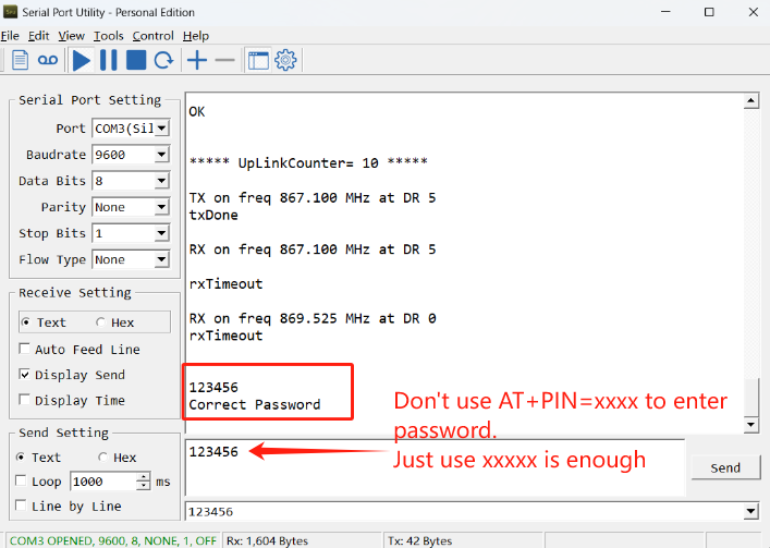
After the Bluetooth or UART connection is successful, use the Serial Access Password to enter the AT command window.
The label on the box of the node will print the initial password: AT+PIN=xxxxxx, and directly use the six-digit password to access the AT instruction window.
If you need to change the password, use AT+PWORD=xxxxxx (6 characters), NB nodes only support lowercase letters.

Note: After entering the command, you need to add a line break, and you can also set automatic line breaks in the Bluetooth tool or UART connection tool.

3.3 AT Commands Set
AT+<CMD>? : Help on <CMD>
AT+<CMD> : Run <CMD>
AT+<CMD>=<value> : Set the value
AT+<CMD>=? : Get the value
General Commands
AT : Attention
AT? : Short Help
ATZ : Trig a reset of the MCU
AT+CFGMOD : Working mode selection
AT+DEUI : Get or set the Device ID
AT+PWORD : Get or set the System password
AT+TDC : Application Data Transmission Interval
AT+CFG : Print all configurations
AT+5VT : Set extend the time of 5V power
AT+PRO : Choose agreement
AT+APN : Get or set the APN
AT+EXT : Get or Set Count value
AT+RXDL : Extend the sending and receiving time
AT+SERVADDR : Server Address
AT+WEIGRE : Get weight or set weight to 0
AT+WEIGAP : Get or Set the GapValue of weight
AT+CFGMOD : Working mode selection
AT+INTMOD : Set the trigger interrupt mode
AT+GETSENSORVALUE : Returns the current sensor measurement
AT+CSQTIME : Get or Set the time to join the network
AT+DNSTIMER :Regularly resolve domain names
AT+TLSMOD : Get or Set the TLS mode
AT+CLOCKLOG : Get or set SHT record time
AT+CDP : Read or Clear cached data
AT+CUM : Get or Set cache upload mechanism (0: Off 1: On)
AT+SERVADDR : Server Address
AT+DNSCFG : Get or Set DNS Server
AT+MQOS : Set the QoS level of MQTT
AT+SLEEP : Get or Set the sleep mode
MQTT Management
AT+CLIENT : Get or Set MQTT client
AT+UNAME : Get or Set MQTT Username
AT+PWD : Get or Set MQTT password
AT+PUBTOPIC : Get or Set MQTT publish topic
AT+SUBTOPIC : Get or Set MQTT subscription topic
Information
AT+FDR1 : Reset parameters to factory default values except for passwords
AT+FDR : Factory Data Reset
AT+PWORD : Serial Access Password
AT+LDATA : Get the last upload data
AT+CDP : Read or Clear cached data
AT+GETLOG : Print serial port logs
COAP Management
AT+URI1 : Get or set CoAP option 1
AT+URI2 : Get or set CoAP option 2
AT+URI3 : Get or set CoAP option 3
AT+URI4 : Get or set CoAP option 4
4. Battery & Power Consumption
SN50v3-NB use ER26500 + SPC1520 battery pack. See below link for detail information about the battery info and how to replace.
Battery Info & Power Consumption Analyze .
5. Firmware update
User can change device firmware to:
- Update with new features.
- Fix bugs.
Firmware and changelog can be downloaded from : Firmware download link
Methods to Update Firmware:
- (Recommended way) OTA firmware update via BLE: Instruction.
- Update through UART TTL interface : Instruction.
6. Get and compile Software
SN50V3-NB is an open-source project, developer can compile their firmware for customized applications. User can get the source code from:
- Software Source Code: https://github.com/dragino/SN50V3-NB
- Compile instruction: http://wiki.dragino.com/xwiki/bin/view/Main/Firmware%20Compile%20Instruction%20--%20STM32/
- Upgrade firmware instruction
See FAQ of this file.
The project file is in: SN50V3-NB\MDK-ARM\uvprojx
7. FAQ
7.1 How can I access the BC660K-GL AT Commands?
User can access to BC660K-GL directly and send AT Commands.
7.2 Why can't the password access AT command after upgrade?
Refer to this link to view the password using STM32Cube Programmer.
8. Order Info
Part Number: SN50v3-NB-XX
XX:
- GE: General version ( Exclude SIM card)
- 1T: with 1NCE * 10 years 500MB SIM card and Pre-configure to ThingsEye server
YY: The grand connector hole size
- M12: M12 hole
- M16: M16 hole
- M20: M20 hole
9. Packing Info
Package Includes:
- SN50v3-NB NB-IoT Sensor Node x 1
- External antenna x 1
Dimension and weight:
Package Size / pcs :
- For SN50v3-NB: 170*80*55 mm
- For SN50v3-NS: 195*125*55 mm
Weight / pcs :
- For SN50v3-NB: 245 g
- For SN50v3-NS: 310 g
10. Support
- Support is provided Monday to Friday, from 09:00 to 18:00 GMT+8. Due to different timezones we cannot offer live support. However, your questions will be answered as soon as possible in the before-mentioned schedule.
- Provide as much information as possible regarding your enquiry (product models, accurately describe your problem and steps to replicate it etc) and send a mail to Support@dragino.cc.
11. FCC Warning
Any Changes or modifications not expressly approved by the party responsible for compliance could void the user's authority to operate the equipment.
This device complies with part 15 of the FCC Rules. Operation is subject to the following two conditions: (1) This device may not cause harmful interference, and (2) this device must accept any interference received, including interference that may cause undesired operation.
Note: This equipment has been tested and found to comply with the limits for a Class B digital device, pursuant to part 15 of the FCC Rules. These limits are designed to provide reasonable protection against harmful interference in a residential installation. This equipment generates, uses and can radiate radio frequency energy and, if not installed and used in accordance with the instructions, may cause harmful interference to radio communications. However, there is no guarantee that interference will not occur in a particular installation. If this equipment does cause harmful interference to radio or television reception, which can be determined by turning the equipment off and on, the user is encouraged to try to correct the interference by one or more of the following measures:
—Reorient or relocate the receiving antenna.
—Increase the separation between the equipment and receiver.
—Connect the equipment into an outlet on a circuit different from that to which the receiver is connected.
—Consult the dealer or an experienced radio/TV technician for help.
This equipment complies with FCC radiation exposure limits set forth for an uncontrolled environment. This equipment should be installed and operated with minimum distance 20cm between the radiator& your body.