POM01-NB -- NB-IoT Power Outage Monitoring Sensor
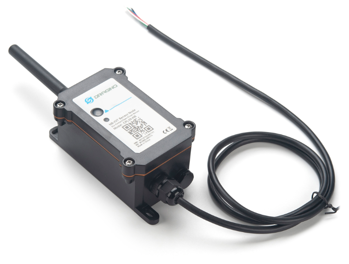
Table of Contents:
- 1. Introduction
- 2. Use POM01-NB to communicate with IoT Server
- 3. Configure POM01-NB
- 4. Battery & Power Consumption
- 5. Firmware update
- 6. FAQ
- 7. Order Info
- 8. Packing Info
- 9. Support
1. Introduction
1.1 What is POM01-NB NB-IoT Power Outage Monitoring Sensor
The POM01-NB integrates NB-IoT wireless module, which sends signals to the cloud platform when triggering alarms or timed reports, and is suitable for remote monitoring scenarios with wide coverage and low power consumption.
The POM01-NB adopts optocoupler isolation technology to detect whether the 220V power supply is normal or not, and can set the 180V low voltage trigger threshold to start the alarm logic immediately when the voltage drops abnormally.
The main power supply of POM01-NB is directly powered by 220V AC, and the backup power can be seamlessly switched after a power failure, guaranteeing continuous operation for 30 days.
POM01-NB has a wide temperature operating range, and the battery supports cyclic charging and discharging, adapting to complex industrial environments.
POM01-NB supports BLE configure and wireless OTA update which make user easy to use.
POM01-NB supports different uplink methods include TCP, MQTT, UDP, MQTTs or CoAP for different application requirement. and Support Uplinks to various IoT Servers.
POM01-NB has optional built-in SIM card and default IoT server connection version. Which makes it works with simple configuration.
1.2 Features
- NB-IoT Bands: B1/B2/B3/B4/B5/B8/B12/B13/B17/B18/B19/B20/B25/B28/B66/B70/B85 @H-FDD
- Ultra-low power consumption
- Power Outage Monitoring
- Uplink via MQTT, MQTTs, TCP, UDP or CoAP
- Support Bluetooth v5.1 remote configure and update firmware
- Uplink on periodically
- Downlink to change configure
- Back up rechargeable 1000mAh battery
1.3 Specification
Common DC Characteristics:
- Supply Voltage: 90 ~230v
- Operating Temperature: -40 ~ 85°C
NB-IoT Spec:
NB-IoT Module: BC660K-GL
Support Bands:
- B1 @H-FDD: 2100MHz
- B2 @H-FDD: 1900MHz
- B3 @H-FDD: 1800MHz
- B4 @H-FDD: 2100MHz
- B5 @H-FDD: 860MHz
- B8 @H-FDD: 900MHz
- B12 @H-FDD: 720MHz
- B13 @H-FDD: 740MHz
- B17 @H-FDD: 730MHz
- B18 @H-FDD: 870MHz
- B19 @H-FDD: 870MHz
- B20 @H-FDD: 790MHz
- B25 @H-FDD: 1900MHz
- B28 @H-FDD: 750MHz
- B66 @H-FDD: 2000MHz
- B70 @H-FDD: 2000MHz
- B85 @H-FDD: 700MHz
Battery:
- Back up rechargeable 1000mAh battery
Power Consumption
- ldle: 4mA
- Transmit: max 40mA
1.4 Applications
- Electricity Meter
- Line Voltage
1.5 Sleep mode and working mode
Deep Sleep Mode: Sensor doesn't have any NB-IoT activate. This mode is used for storage and shipping to save battery life.
Working Mode: In this mode, Sensor will work as NB-IoT Sensor to Join NB-IoT network and send out sensor data to server. Between each sampling/tx/rx periodically, sensor will be in IDLE mode), in IDLE mode, sensor has the same power consumption as Deep Sleep mode.
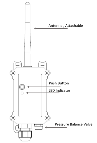
1.6 Button & LEDs
| Behavior on ACT | Function | Action |
|---|---|---|
| Pressing ACT between 1s < time < 3s | Send an uplink | If sensor has already attached to NB-IoT network, sensor will send an uplink packet, blue led will blink once. |
| Pressing ACT for more than 3s | Active Device | Green led will fast blink 5 times, device will enter OTA mode for 3 seconds. And then start to attach NB-IoT network. |
| Fast press ACT 5 times. | Deactivate Device | Red led will solid on for 5 seconds. Means device is in Deep Sleep Mode. |
1.7 BLE connection
POM01-NB support BLE remote configure and firmware update.
BLE can be used to configure the parameter of sensor or see the console output from sensor. BLE will be only activate on below case:
- Press button to send an uplink
- Press button to active device.
- Device Power on or reset.
If there is no activity connection on BLE in 60 seconds, sensor will shut down BLE module to enter low power mode.
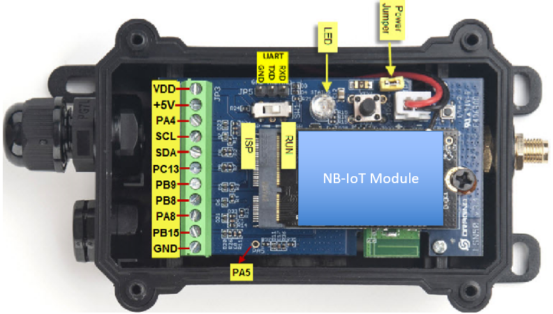
1.8 Pin Definitions , Switch & SIM Direction
1.8.1 Jumper JP2
Power on Device when put this jumper.
Power off device when take out this jumper
1.8.2 BOOT MODE / SW1
1) ISP: upgrade mode, device won't have any signal in this mode. but ready for upgrade firmware. LED won't work. Firmware won't run.
2) Flash: work mode, device starts to work and send out console output for further debug
1.8.3 Reset Button
Press to reboot the device.
1.8.4 SIM Card Direction
See this link. How to insert SIM Card.
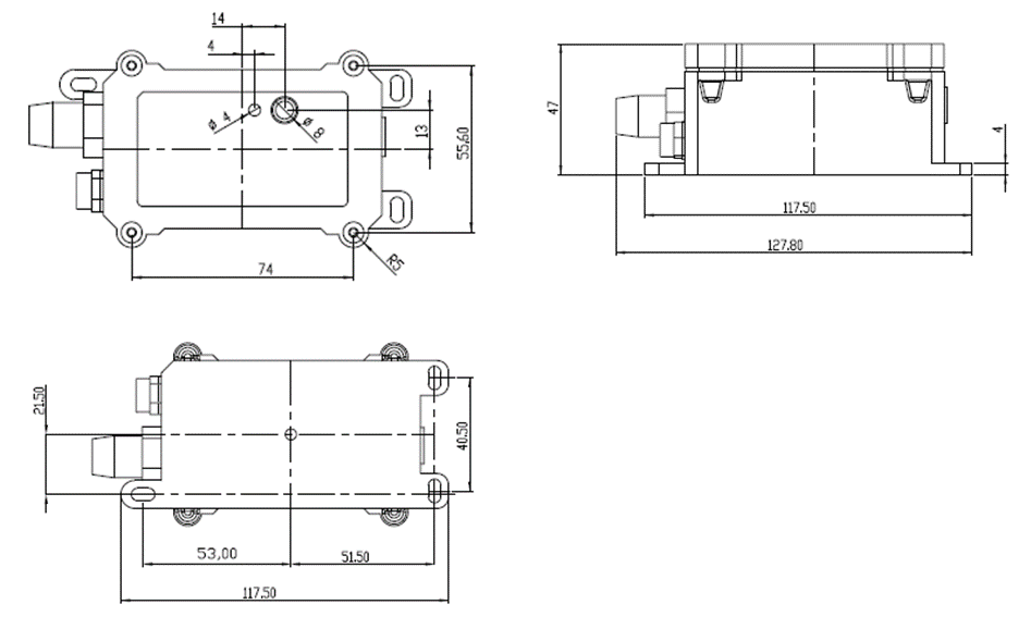
1.9 Mechanical
1.10 Hardware connection
1.10.1 Pins of AC detect module


1.10.2 Connection between AC detect module and POM01-NB motherboard
- VBAT <---> VDD
- DATA1 <---> PA8 (Tentative as interrupt pin 1)
- DATA2 <---> PB15 (Tentative as interrupt pin 2)
- GND <---> GND

1.10.3 Connection between AC detect module and AC power supply(90 ~230v)
- AC_N <---> AC power supply N
- AC_L <---> AC power supply L

2. Use POM01-NB to communicate with IoT Server
2.1 Send data to IoT server via NB-IoT network
The POM01-NB is equipped with a NB-IoT module, the pre-loaded firmware in POM01-NB will get environment data from sensors and send the value to local NB-IoT network via the NB-IoT module. The NB-IoT network will forward this value to IoT server via the protocol defined by POM01-NB.
Below shows the network structure:
There are two version: -GE and -1T version of POM01-NB.
GE Version: This version doesn't include SIM card or point to any IoT server. User needs to use AT Commands to configure below two steps to set POM01-NB send data to IoT server.
- Install NB-IoT SIM card and configure APN. See instruction of Attach Network.
- Set up sensor to point to IoT Server. See instruction of Configure to Connect Different Servers.
Below shows result of different server as a glance.
| Servers | Dash Board | Comments |
| Node-Red | 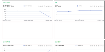
| |
| DataCake | 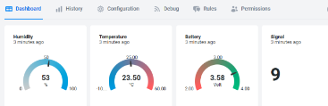
| |
| Tago.IO | ||
| General UDP | Raw Payload. Need Developer to design Dash Board | |
| General MQTT | Raw Payload. Need Developer to design Dash Board | |
| ThingSpeak | 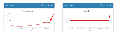
| |
| ThingsBoard | 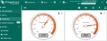
|
1T Version: This version has 1NCE SIM card pre-installed and configure to send value to ThingsEye. User Just need to select the sensor type in ThingsEyeand Activate POM01-NB and user will be able to see data in ThingsEye. See here for ThingsEye Config Instruction.
2.2 Payload Types
To meet different server requirement, POM01-NB supports different payload type.
Includes:
- General JSON format payload. (Type=5)
- HEX format Payload. (Type=0)
- ThingSpeak Format. (Type=1)
- ThingsBoard Format. (Type=3)
User can specify the payload type when choose the connection protocol. Example:
AT+PRO=1,0 // Use COAP Connection & hex Payload
AT+PRO=1,5 // Use COAP Connection & Json Payload
AT+PRO=2,0 // Use UDP Connection & hex Payload
AT+PRO=2,5 // Use UDP Connection & Json Payload
AT+PRO=3,0 // Use MQTT Connection & hex Payload
AT+PRO=3,5 // Use MQTT Connection & Json Payload
AT+PRO=4,0 // Use TCP Connection & hex Payload
AT+PRO=4,5 // Use TCP Connection & Json Payload
2.2.1 General Json Format(Type=5)
2.2.2 HEX format Payload(Type=0)
3. Configure POM01-NB
3.1 Configure Methods
POM01-NB supports below configure method:
- AT Command via Bluetooth Connection (Recommended): BLE Configure Instruction.
- AT Command via UART Connection : See UART Connection.
3.2 Serial Access Password
After the Bluetooth or UART connection is successful, use the Serial Access Password to enter the AT command window.
The label on the box of the node will print the initial password: AT+PIN=xxxxxx, and directly use the six-digit password to access the AT instruction window.
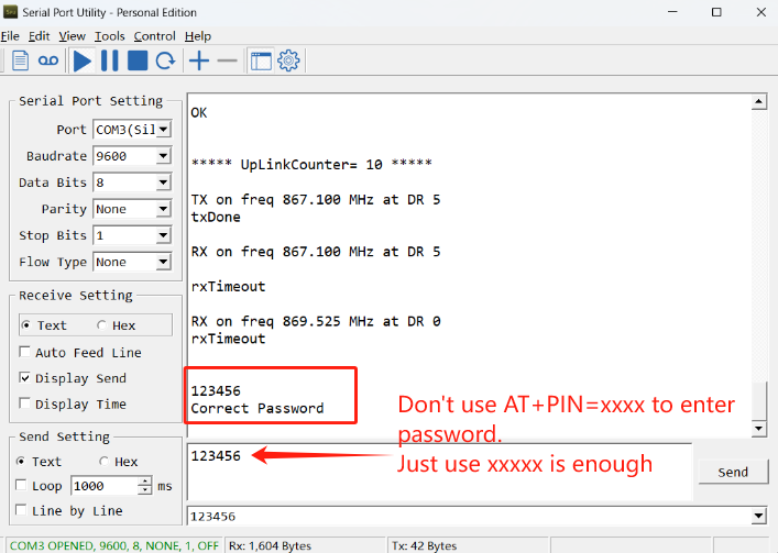
If you need to change the password, use AT+PWORD=xxxxxx (6 characters), -CB nodes only support lowercase letters.
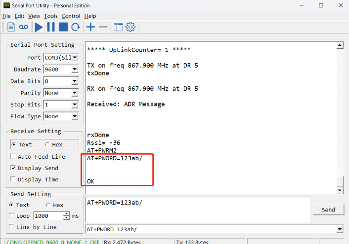
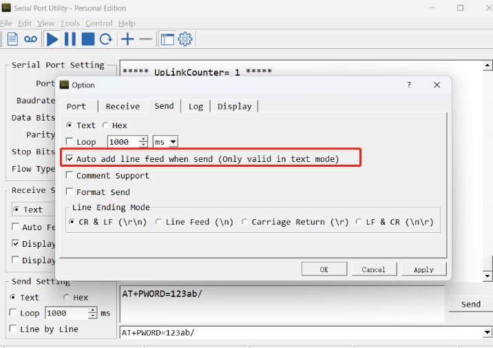
Note: After entering the command, you need to add a line break, and you can also set automatic line breaks in the Bluetooth tool or UART connection tool.
3.3 AT Commands Set
4. Battery & Power Consumption
LPOM01-NB use ER26500 + SPC1520 battery pack and POM01-NB use 3000mAh Recharable Battery with Solar Panel. See below link for detail information about the battery info and how to replace.
Battery Info & Power Consumption Analyze .
5. Firmware update
User can change device firmware to:
- Update with new features.
- Fix bugs.
Firmware and changelog can be downloaded from : Firmware download link (To be updated...)
Methods to Update Firmware:
- (Recommended way) OTA firmware update via BLE: Instruction.
- Update through UART TTL interface : Instruction.
6. FAQ
6.1 How can I access the BC660K-GL AT Commands?
User can access to BC660K-GL directly and send AT Commands.
7. Order Info
Part Number: POM01-NB-XX
XX:
- GE: General version ( Exclude SIM card)
- 1T: with 1NCE * 10 years 500MB SIM card and Pre-configure to ThingsEye server
8. Packing Info
Package Includes:
- POM01-NB NB-IoT Power Outage Monitoring Sensor x 1
Dimension and weight:
- Device Size: cm
- Device Weight: g
- Package Size / pcs : cm
- Weight / pcs : g
9. Support
- Support is provided Monday to Friday, from 09:00 to 18:00 GMT+8. Due to different timezones we cannot offer live support. However, your questions will be answered as soon as possible in the before-mentioned schedule.
- Provide as much information as possible regarding your enquiry (product models, accurately describe your problem and steps to replicate it etc) and send a mail to support@dragino.com.