SN50v3-LB User Manual

Table of Contents:
- 1. Introduction
- 2. Configure SN50v3-LB to connect to LoRaWAN network
- 2.1 How it works
- 2.2 Quick guide to connect to LoRaWAN server (OTAA)
- 2.3 Uplink Payload
- 2.3.1 Device Status, FPORT=5
- 2.3.2 Working Modes & Sensor Data. Uplink via FPORT=2
- 2.3.2.1 MOD=1 (Default Mode)
- 2.3.2.2 MOD=2 (Distance Mode)
- 2.3.2.3 MOD=3 (3 ADC + I2C)
- 2.3.2.4 MOD=4 (3 x DS18B20)
- 2.3.2.5 MOD=5(Weight Measurement by HX711)
- 2.3.2.6 MOD=6 (Counting Mode)
- 2.3.2.7 MOD=7 (Three interrupt contact modes)
- 2.3.2.8 MOD=8 (3ADC+1DS18B20)
- 2.3.2.9 MOD=9 (3DS18B20+ two Interrupt count mode)
- 2.3.3 Decode payload
- 2.3.3.1 Battery Info
- 2.3.3.2 Temperature (DS18B20)
- 2.3.3.3 Digital Input
- 2.3.3.4 Analogue Digital Converter (ADC)
- 2.3.3.5 Digital Interrupt
- 2.3.3.6 I2C Interface (SHT20)
- 2.3.3.7 Distance Reading
- 2.3.3.8 Ultrasonic Sensor
- 2.3.3.9 Battery Output - BAT pin
- 2.3.3.10 +5V Output
- 2.3.3.11 BH1750 Illumination Sensor
- 2.3.3.12 Working MOD
- 2.4 Payload Decoder file
- 2.5 Frequency Plans
- 3. Configure SN50v3-LB
- 4. Battery & Power Consumption
- 5. OTA Firmware update
- 6. FAQ
- 7. Order Info
- 8. Packing Info
- 9. Support
1. Introduction
1.1 What is SN50v3-LB LoRaWAN Generic Node
SN50V3-LB LoRaWAN Sensor Node is a Long Range LoRa Sensor Node. It is designed for outdoor use and powered by 8500mA Li/SOCl2 battery for long term use.SN50V3-LB is designed to facilitate developers to quickly deploy industrial level LoRa and IoT solutions. It help users to turn the idea into a practical application and make the Internet of Things a reality. It is easy to program, create and connect your things everywhere.
SN50V3-LB wireless part is based on SX1262 allows the user to send data and reach extremely long ranges at low data-rates.It provides ultra-long range spread spectrum communication and high interference immunity whilst minimising current consumption.It targets professional wireless sensor network applications such as irrigation systems, smart metering, smart cities, smartphone detection, building automation, and so on.
SN50V3-LB has a powerful 48Mhz ARM microcontroller with 256KB flash and 64KB RAM. It has multiplex I/O pins to connect to different sensors.
SN50V3-LB has a built-in BLE module, user can configure the sensor remotely via Mobile Phone. It also support OTA upgrade via private LoRa protocol for easy maintaining.
SN50V3-LB is the 3rd generation of LSN50 series generic sensor node from Dragino. It is an open source project and has a mature LoRaWAN stack and application software. User can use the pre-load software for their IoT projects or easily customize the software for different requirements.
1.2 Features
- LoRaWAN 1.0.3 Class A
- Ultra-low power consumption
- Open-Source hardware/software
- Bands: CN470/EU433/KR920/US915/EU868/AS923/AU915/IN865
- Support Bluetooth v5.1 and LoRaWAN remote configure
- Support wireless OTA update firmware
- Uplink on periodically
- Downlink to change configure
- 8500mAh Battery for long term use
1.3 Specification
Common DC Characteristics:
- Supply Voltage: built in 8500mAh Li-SOCI2 battery , 2.5v ~ 3.6v
- Operating Temperature: -40 ~ 85°C
I/O Interface:
- Battery output (2.6v ~ 3.6v depends on battery)
- +5v controllable output
- 3 x Interrupt or Digital IN/OUT pins
- 3 x one-wire interfaces
- 1 x UART Interface
- 1 x I2C Interface
LoRa Spec:
- Frequency Range, Band 1 (HF): 862 ~ 1020 Mhz
- Max +22 dBm constant RF output vs.
- RX sensitivity: down to -139 dBm.
- Excellent blocking immunity
Battery:
- Li/SOCI2 un-chargeable battery
- Capacity: 8500mAh
- Self-Discharge: <1% / Year @ 25°C
- Max continuously current: 130mA
- Max boost current: 2A, 1 second
Power Consumption
- Sleep Mode: 5uA @ 3.3v
- LoRa Transmit Mode: 125mA @ 20dBm, 82mA @ 14dBm
1.4 Sleep mode and working mode
Deep Sleep Mode: Sensor doesn't have any LoRaWAN activate. This mode is used for storage and shipping to save battery life.
Working Mode: In this mode, Sensor will work as LoRaWAN Sensor to Join LoRaWAN network and send out sensor data to server. Between each sampling/tx/rx periodically, sensor will be in IDLE mode), in IDLE mode, sensor has the same power consumption as Deep Sleep mode.
1.5 Button & LEDs
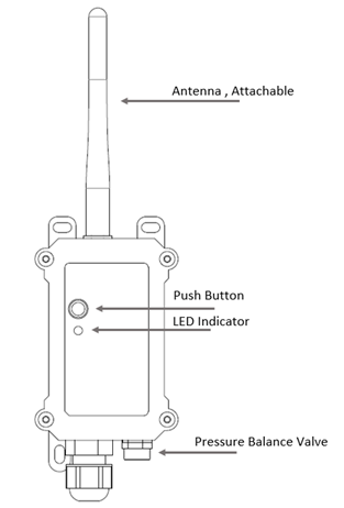
| Behavior on ACT | Function | Action |
|---|---|---|
| Pressing ACT between 1s < time < 3s | Send an uplink | If sensor is already Joined to LoRaWAN network, sensor will send an uplink packet, blue led will blink once. |
| Pressing ACT for more than 3s | Active Device | Green led will fast blink 5 times, device will enter OTA mode for 3 seconds. And then start to JOIN LoRaWAN network. |
| Fast press ACT 5 times. | Deactivate Device | Red led will solid on for 5 seconds. Means device is in Deep Sleep Mode. |
1.6 BLE connection
SN50v3-LB supports BLE remote configure.
BLE can be used to configure the parameter of sensor or see the console output from sensor. BLE will be only activate on below case:
- Press button to send an uplink
- Press button to active device.
- Device Power on or reset.
If there is no activity connection on BLE in 60 seconds, sensor will shut down BLE module to enter low power mode.
1.7 Pin Definitions

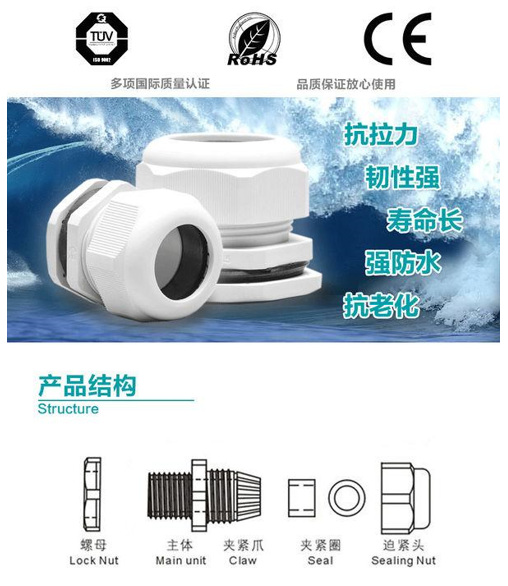
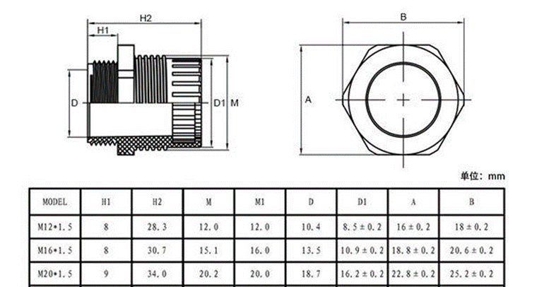
1.8 Mechanical
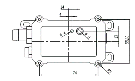
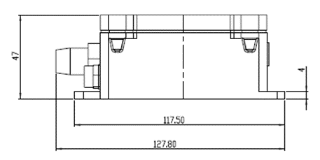
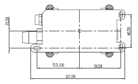
Hole Option
SN50v3-LB has different hole size options for different size sensor cable. The options provided are M12, M16 and M20. The definition is as below:
2. Configure SN50v3-LB to connect to LoRaWAN network
2.1 How it works
The SN50v3-LB is configured as LoRaWAN OTAA Class A mode by default. It has OTAA keys to join LoRaWAN network. To connect a local LoRaWAN network, you need to input the OTAA keys in the LoRaWAN IoT server and press the button to activate the S31x-LB. It will automatically join the network via OTAA and start to send the sensor value. The default uplink interval is 20 minutes.
2.2 Quick guide to connect to LoRaWAN server (OTAA)
Following is an example for how to join the TTN v3 LoRaWAN Network. Below is the network structure; we use the LPS8v2 as a LoRaWAN gateway in this example.
The LPS8V2 is already set to connected to TTN network , so what we need to now is configure the TTN server.
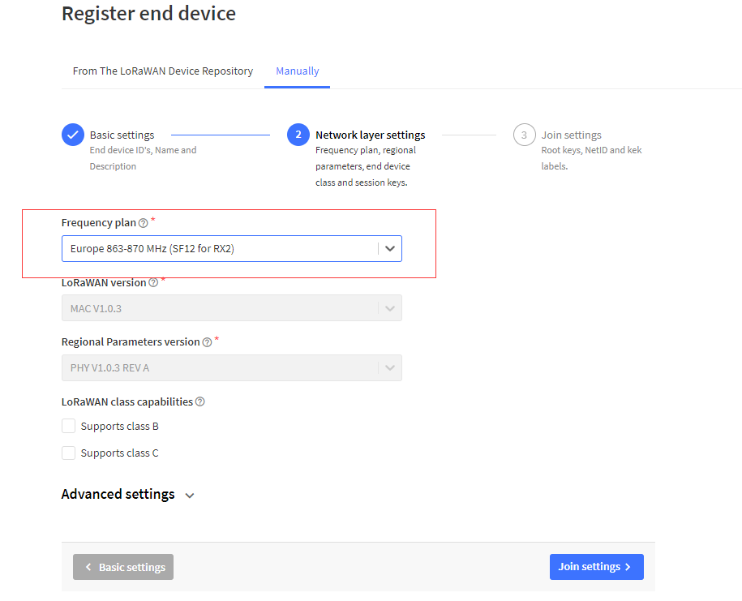
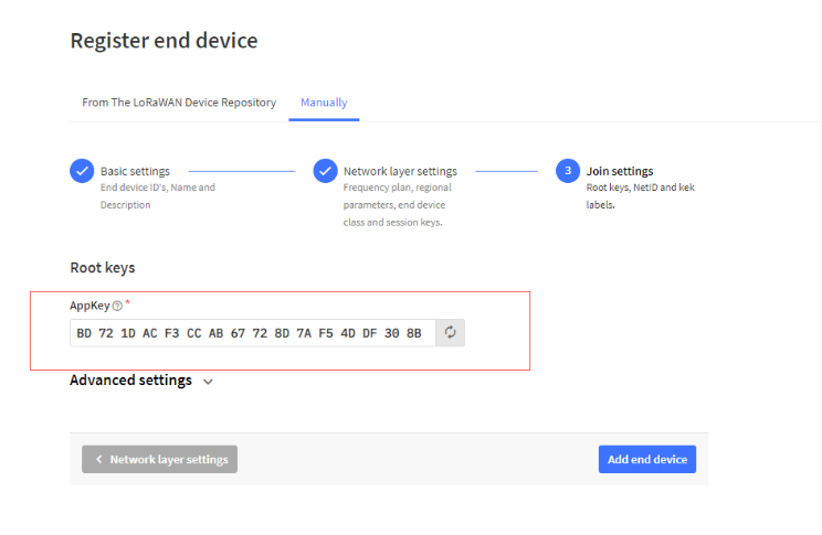
Step 1: Create a device in TTN with the OTAA keys from SN50v3-LB.
Each SN50v3-LB is shipped with a sticker with the default device EUI as below:
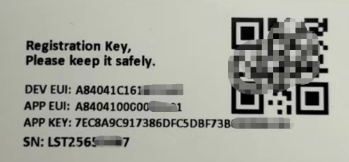
You can enter this key in the LoRaWAN Server portal. Below is TTN screen shot:
Register the device
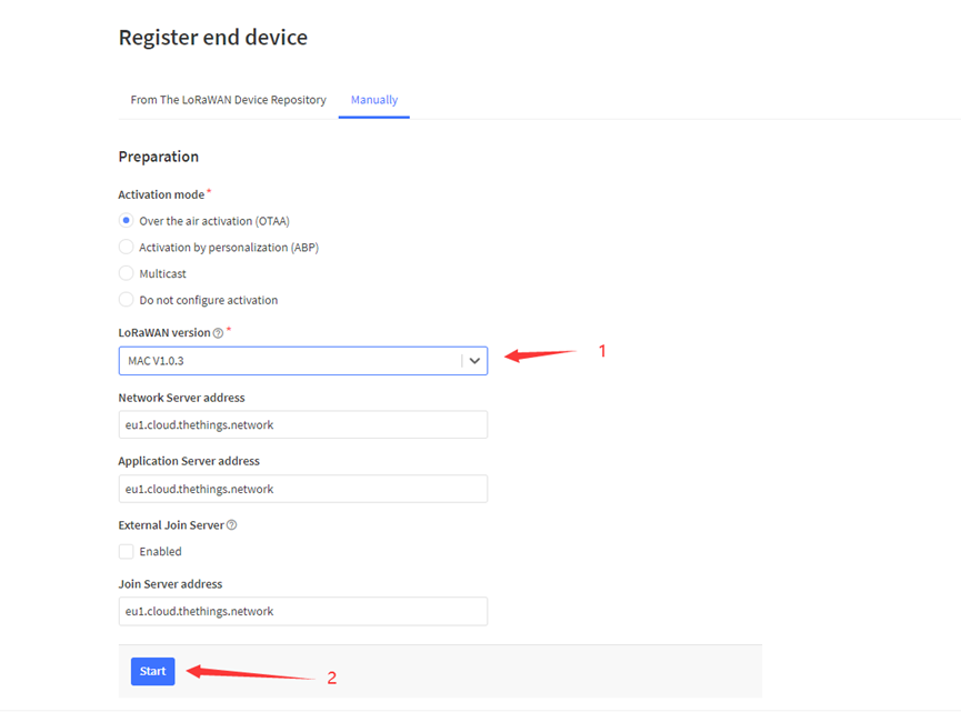
Add APP EUI and DEV EUI
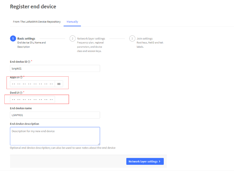
Add APP EUI in the application
Add APP KEY
Step 2: Activate SN50v3-LB
Press the button for 5 seconds to activate the SN50v3-LB.
Green led will fast blink 5 times, device will enter OTA mode for 3 seconds. And then start to JOIN LoRaWAN network. Green led will solidly turn on for 5 seconds after joined in network.
After join success, it will start to upload messages to TTN and you can see the messages in the panel.
2.3 Uplink Payload
2.3.1 Device Status, FPORT=5
Users can use the downlink command(0x26 01) to ask SN50v3 to send device configure detail, include device configure status. SN50v3 will uplink a payload via FPort=5 to server.
The Payload format is as below.
| Device Status (FPORT=5) | |||||
| Size (bytes) | 1 | 2 | 1 | 1 | 2 |
| Value | Sensor Model | Firmware Version | Frequency Band | Sub-band | BAT |
Example parse in TTNv3
Sensor Model: For SN50v3, this value is 0x1C
Firmware Version: 0x0100, Means: v1.0.0 version
Frequency Band:
*0x01: EU868
*0x02: US915
*0x03: IN865
*0x04: AU915
*0x05: KZ865
*0x06: RU864
*0x07: AS923
*0x08: AS923-1
*0x09: AS923-2
*0x0a: AS923-3
*0x0b: CN470
*0x0c: EU433
*0x0d: KR920
*0x0e: MA869
Sub-Band:
AU915 and US915:value 0x00 ~ 0x08
CN470: value 0x0B ~ 0x0C
Other Bands: Always 0x00
Battery Info:
Check the battery voltage.
Ex1: 0x0B45 = 2885mV
Ex2: 0x0B49 = 2889mV
2.3.2 Working Modes & Sensor Data. Uplink via FPORT=2
SN50v3 has different working mode for the connections of different type of sensors. This section describes these modes. Use can use the AT Command AT+MOD to set SN50v3 to different working modes.
For example:
AT+MOD=2 // will set the SN50v3 to work in MOD=2 distance mode which target to measure distance via Ultrasonic Sensor.
Important Notice:
- Some working modes has payload more than 12 bytes, The US915/AU915/AS923 frequency bands' definition has maximum 11 bytes in DR0. Server sides will see NULL payload while SN50v3 transmit in DR0 with 12 bytes payload.
- All modes share the same Payload Explanation from HERE.
- By default, the device will send an uplink message every 20 minutes.
2.3.2.1 MOD=1 (Default Mode)
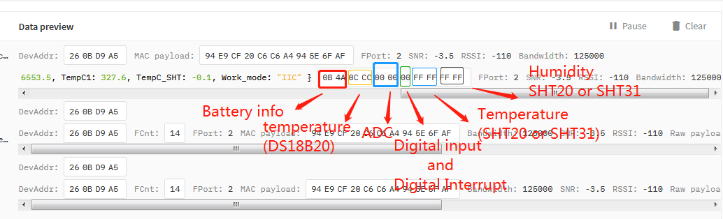
In this mode, uplink payload includes in total 11 bytes. Uplink packets use FPORT=2.
| Size(bytes) | 2 | 2 | 2 | 1 | 2 | 2 |
| Value | Bat | Temperature(DS18B20) | ADC | Digital in & Digital Interrupt | Temperature(SHT20 or SHT31 or BH1750 Illumination Sensor | Humidity(SHT20) |
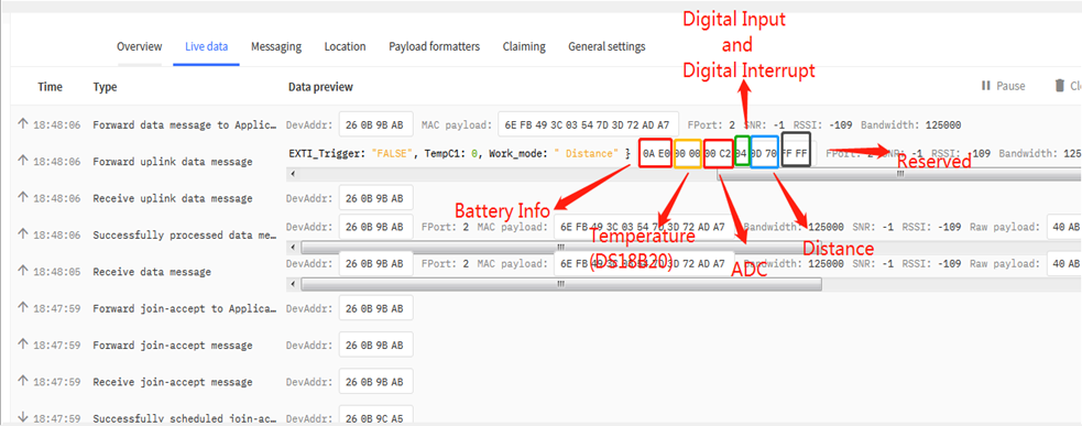
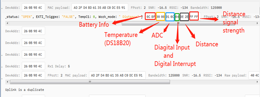
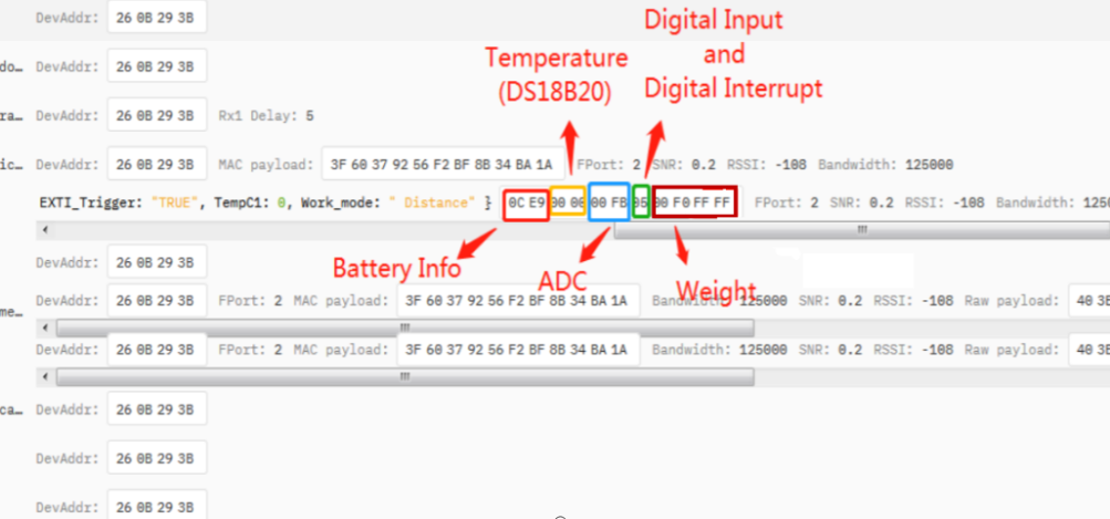
2.3.2.2 MOD=2 (Distance Mode)
This mode is target to measure the distance. The payload of this mode is totally 11 bytes. The 8th and 9th bytes is for the distance.
| Size(bytes) | 2 | 2 | 2 | 1 | 2 | 2 |
| Value | BAT | Temperature(DS18B20) | ADC | Digital in & Digital Interrupt | Distance measure by: | Reserved |
Connection of LIDAR-Lite V3HP:
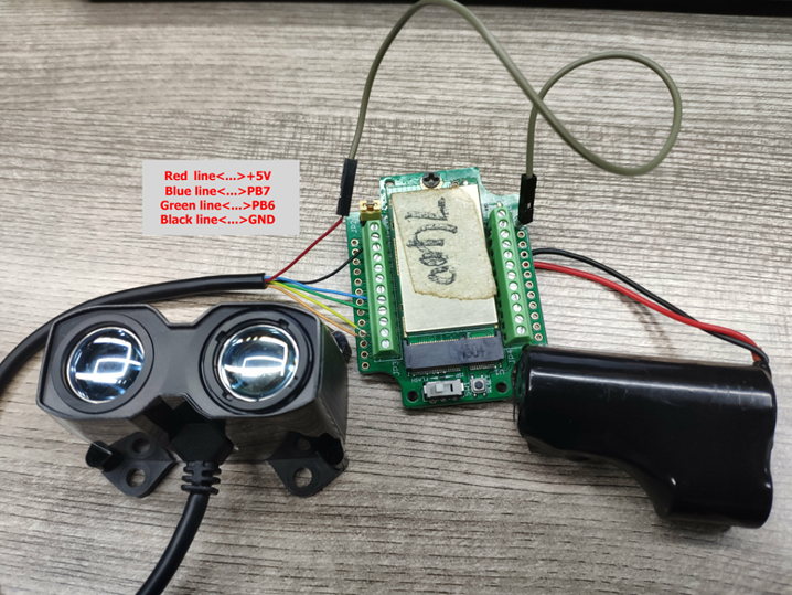
Connection to Ultrasonic Sensor:
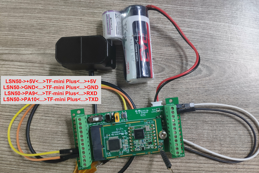
For the connection to TF-Mini or TF-Luna , MOD2 payload is as below:
| Size(bytes) | 2 | 2 | 1 | 2 | 2 | 2 |
| Value | BAT | Temperature(DS18B20) | Digital in & Digital Interrupt | ADC | Distance measure by:1)TF-Mini plus LiDAR | Distance signal strength |
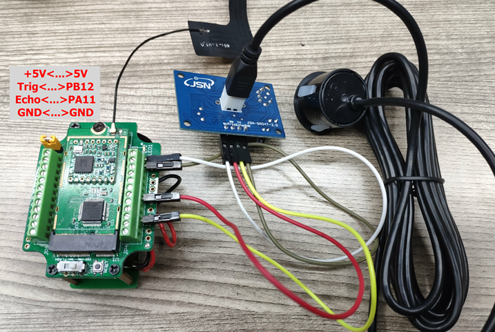
Connection to TF-Mini plus LiDAR(UART version):
Need to remove R3 and R4 resistors to get low power. Since firmware v1.7.0
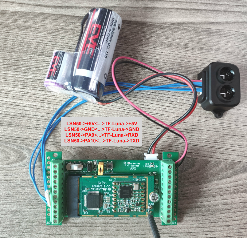
Connection to TF-Luna LiDAR (UART version):
Need to remove R3 and R4 resistors to get low power. Since firmware v1.7.0
Please use firmware version > 1.6.5 when use MOD=2, in this firmware version, user can use LSn50 v1 to power the ultrasonic sensor directly and with low power consumption.
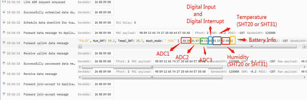
2.3.2.3 MOD=3 (3 ADC + I2C)
This mode has total 12 bytes. Include 3 x ADC + 1x I2C
Size(bytes) | 2 | 2 | 2 | 1 | 2 | 2 | 1 |
|---|---|---|---|---|---|---|---|
| Value | ADC(Pin PA0) | ADC2(PA1) | ADC3 (PA4) | Digital in(PA12)&Digital Interrupt1(PB14) | Temperature(SHT20 or SHT31 or BH1750 Illumination Sensor) | Humidity(SHT20 or SHT31) | Bat |
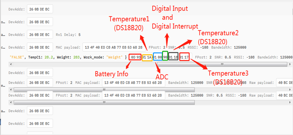
2.3.2.4 MOD=4 (3 x DS18B20)
This mode is supported in firmware version since v1.6.1. Software set to AT+MOD=4
Hardware connection is as below,
( Note:
- In hardware version v1.x and v2.0 , R3 & R4 should change from 10k to 4.7k ohm to support the other 2 x DS18B20 probes.
- In hardware version v2.1 no need to change R3 , R4, by default, they are 4.7k ohm already.
See here for hardware changelog. )
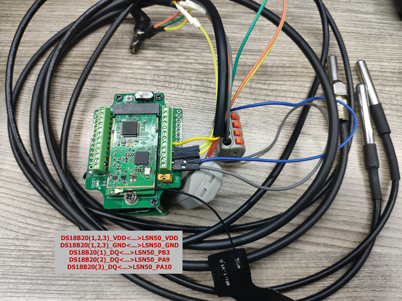
This mode has total 11 bytes. As shown below:
| Size(bytes) | 2 | 2 | 2 | 1 | 2 | 2 |
| Value | BAT | Temperature1 | ADC | Digital in & Digital Interrupt | Temperature2 (DS18B20) (PA9) | Temperature3 (DS18B20) (PA10) |
2.3.2.5 MOD=5(Weight Measurement by HX711)
This mode is supported in firmware version since v1.6.2. Please use v1.6.5 firmware version so user no need to use extra LDO for connection.
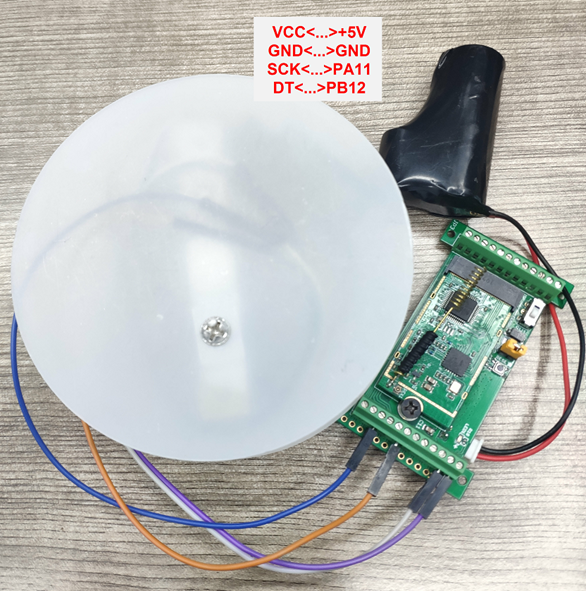
Each HX711 need to be calibrated before used. User need to do below two steps:
- Zero calibration. Don't put anything on load cell and run AT+WEIGRE to calibrate to Zero gram.
- Adjust calibration factor (default value 400): Put a known weight thing on load cell and run AT+WEIGAP to adjust the Calibration Factor.
Remove the limit of plus or minus 5Kg in mode 5, and expand from 2 bytes to 4 bytes, the unit is g.(Since v1.8.0)
For example:
AT+WEIGAP =403.0
Response: Weight is 401 g
Check the response of this command and adjust the value to match the real value for thing.
Size(bytes) | 2 | 2 | 2 | 1 | 4 | 2 |
|---|---|---|---|---|---|---|
| Value | Bat | Temperature(DS18B20) | ADC | Digital Input and Digitak Interrupt | Weight | Reserved |
2.3.2.6 MOD=6 (Counting Mode)
In this mode, the device will work in counting mode. It counts the interrupt on the interrupt pins and sends the count on TDC time.
Connection is as below. The PIR sensor is a count sensor, it will generate interrupt when people come close or go away. User can replace the PIR sensor with other counting sensors.
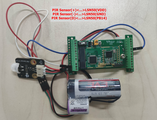
Note: LoRaWAN wireless transmission will infect the PIR sensor. Which cause the counting value increase +1 for every uplink. User can change PIR sensor or put sensor away of the LSN50 to avoid this happen.
| Size(bytes) | 2 | 2 | 2 | 1 | 4 |
|---|---|---|---|---|---|
| Value | BAT | ADC | Digital in | Count |
2.3.2.7 MOD=7 (Three interrupt contact modes)
Size(bytes) | 2 | 2 | 2 | 1 | 1 | 1 | 2 |
|---|---|---|---|---|---|---|---|
| Value | BAT | Temperature(DS18B20) | ADC | Digital in(PA12)&Digital Interrupt1(PB14) | Digital Interrupt2(PB15) | Digital Interrupt3(PA4) | Reserved |
2.3.2.8 MOD=8 (3ADC+1DS18B20)
Size(bytes) | 2 | 2 | 2 | 1 | 2 | 2 |
|---|---|---|---|---|---|---|
| Value | BAT | Temperature(DS18B20) | ADC1(PA0) | Digital in | ADC2(PA1) | ADC3(PA4) |
2.3.2.9 MOD=9 (3DS18B20+ two Interrupt count mode)
Size(bytes) | 2 | 2 | 2 | 1 | 2 | 4 | 4 |
|---|---|---|---|---|---|---|---|
| Value | BAT | Temperature1(PB3) | Temperature2(PA9) | Digital in | Temperature3(PA10) | Count1(PB14) | Count2(PB15) |
The newly added AT command is issued correspondingly:
AT+INTMOD1 PB14 pin: Corresponding downlink: 06 00 00 xx
AT+INTMOD2 PB15 pin: Corresponding downlink: 06 00 01 xx
AT+INTMOD3 PA4 pin: Corresponding downlink: 06 00 02 xx
AT+SETCNT=aa,bb
When AA is 1, set the count of PB14 pin to BB Corresponding downlink:09 01 bb bb bb bb
When AA is 2, set the count of PB15 pin to BB Corresponding downlink:09 02 bb bb bb bb
2.3.3 Decode payload
While using TTN V3 network, you can add the payload format to decode the payload.
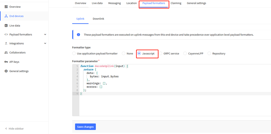
The payload decoder function for TTN V3 are here:
SN50v3 TTN V3 Payload Decoder: https://github.com/dragino/dragino-end-node-decoder
2.3.3.1 Battery Info
Check the battery voltage for SN50v3.
Ex1: 0x0B45 = 2885mV
Ex2: 0x0B49 = 2889mV
2.3.3.2 Temperature (DS18B20)
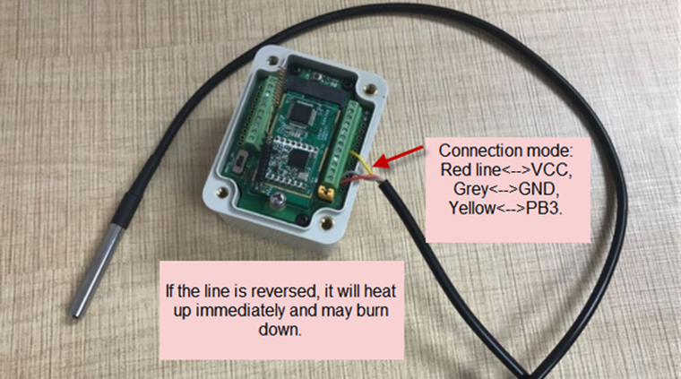
If there is a DS18B20 connected to PB3 pin. The temperature will be uploaded in the payload.
More DS18B20 can check the 3 DS18B20 mode
Connection:
Example:
If payload is: 0105H: (0105 & 8000 == 0), temp = 0105H /10 = 26.1 degree
If payload is: FF3FH : (FF3F & 8000 == 1) , temp = (FF3FH - 65536)/10 = -19.3 degrees.
(FF3F & 8000:Judge whether the highest bit is 1, when the highest bit is 1, it is negative)
2.3.3.3 Digital Input
The digital input for pin PA12,
- When PA12 is high, the bit 1 of payload byte 6 is 1.
- When PA12 is low, the bit 1 of payload byte 6 is 0.
2.3.3.4 Analogue Digital Converter (ADC)
The ADC pins in LSN50 can measure range from 0~Vbat, it use reference voltage from . If user need to measure a voltage > VBat, please use resistors to divide this voltage to lower than VBat, otherwise, it may destroy the ADC pin.
Note: minimum VBat is 2.5v, when batrrey lower than this value. Device won't be able to send LoRa Uplink.
The ADC monitors the voltage on the PA0 line, in mV.
Ex: 0x021F = 543mv,
Example1: Reading an Oil Sensor (Read a resistance value):
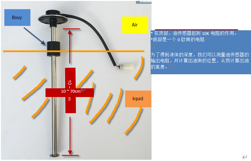
In the LSN50, we can use PB4 and PA0 pin to calculate the resistance for the oil sensor.
Steps:
- Solder a 10K resistor between PA0 and VCC.
- Screw oil sensor's two pins to PA0 and PB4.
The equipment circuit is as below:
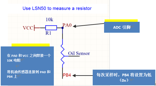
According to above diagram:
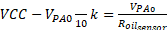
So
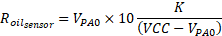
 is the reading of ADC. So if ADC=0x05DC=0.9 v and VCC (BAT) is 2.9v
The 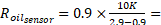 4.5K ohm
Since the Bouy is linear resistance from 10 ~ 70cm.
The position of Bouy is 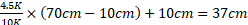 , from the bottom of Bouy.
2.3.3.5 Digital Interrupt
Digital Interrupt refers to pin PB14, and there are different trigger methods. When there is a trigger, the SN50v3 will send a packet to the server.
Interrupt connection method:
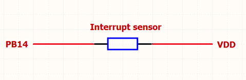
Example to use with door sensor :
The door sensor is shown at right. It is a two wire magnetic contact switch used for detecting the open/close status of doors or windows.
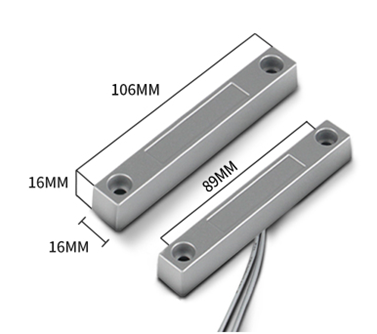
When the two pieces are close to each other, the 2 wire output will be short or open (depending on the type), while if the two pieces are away from each other, the 2 wire output will be the opposite status. So we can use LSN50 interrupt interface to detect the status for the door or window.
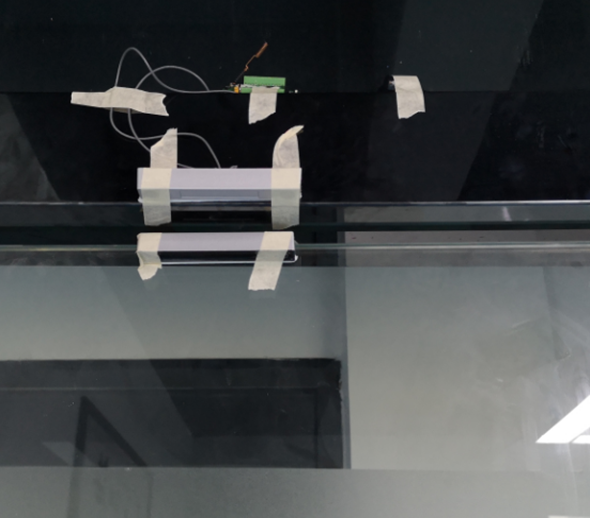
Below is the installation example:
Fix one piece of the magnetic sensor to the door and connect the two pins to LSN50 as follows:
One pin to LSN50's PB14 pin
The other pin to LSN50's VCC pin
Install the other piece to the door. Find a place where the two pieces will be close to each other when the door is closed. For this particular magnetic sensor, when the door is closed, the output will be short, and PB14 will be at the VCC voltage.
Door sensors have two types: NC (Normal close) and NO (normal open). The connection for both type sensors are the same. But the decoding for payload are reverse, user need to modify this in the IoT Server decoder.
When door sensor is shorted, there will extra power consumption in the circuit, the extra current is 3v3/R14 = 3v2/1Mohm = 0.3uA which can be ignored.
The above photos shows the two parts of the magnetic switch fitted to a door.
The software by default uses the falling edge on the signal line as an interrupt. We need to modify it to accept both the rising edge (0v --> VCC , door close) and the falling edge (VCC --> 0v , door open) as the interrupt.
The command is:
AT+INTMOD=1 //(more info about INMOD please refer AT Command Manual. )
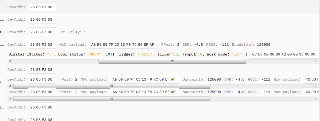
Below shows some screen captures in TTN V3:
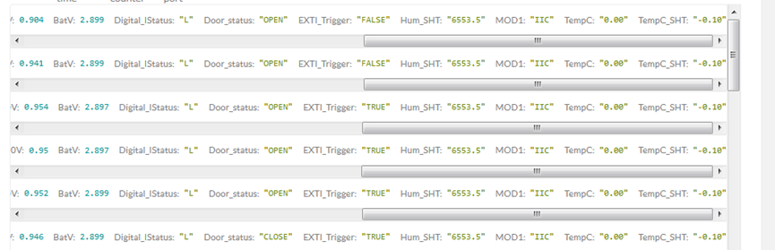
In MOD=1, user can use byte 6 to see the status for door open or close. TTN V3 decoder is as below:
door= (bytes[6] & 0x80)? "CLOSE":"OPEN";
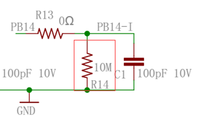
Notice for hardware version LSN50 v1 < v1.3 (produced before 2018-Nov).
In this hardware version, there is no R14 resistance solder. When use the latest firmware, it should set AT+INTMOD=0 to close the interrupt. If user need to use Interrupt in this hardware version, user need to solder R14 with 10M resistor and C1 (0.1uF) on board.
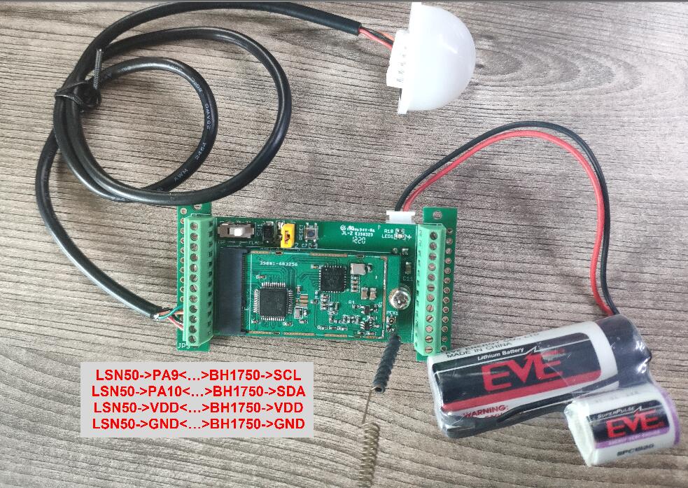
2.3.3.6 I2C Interface (SHT20)
The PB6(SDA) and PB7(SCK) are I2C interface lines. You can use these to connect to an I2C device and get the sensor data.
We have made an example to show how to use the I2C interface to connect to the SHT20 Temperature and Humidity Sensor. This is supported in the stock firmware since v1.5 with AT+MOD=1 (default value).
Notice: Different I2C sensors have different I2C commands set and initiate process, if user want to use other I2C sensors, User need to re-write the source code to support those sensors. SHT20 code in LSN50 will be a good reference.
Below is the connection to SHT20/ SHT31. The connection is as below:
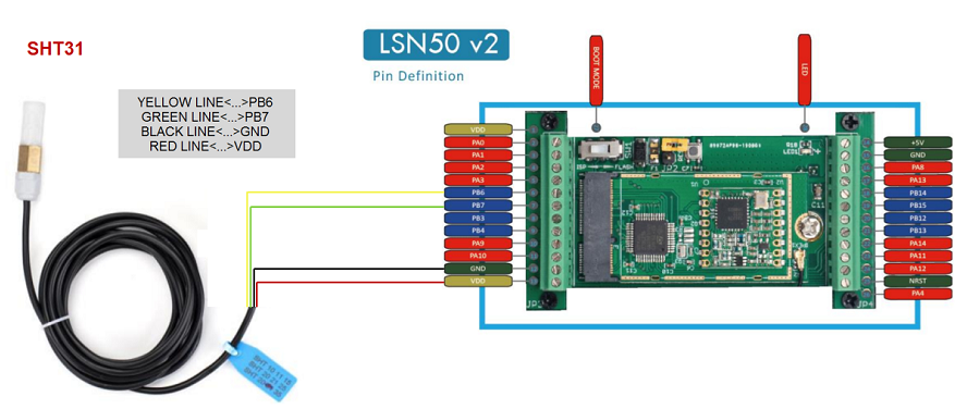
The device will be able to get the I2C sensor data now and upload to IoT Server.
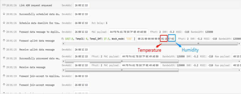
Convert the read byte to decimal and divide it by ten.
Example:
Temperature: Read:0116(H) = 278(D) Value: 278 /10=27.8℃;
Humidity: Read:0248(H)=584(D) Value: 584 / 10=58.4, So 58.4%
If you want to use other I2C device, please refer the SHT20 part source code as reference.
2.3.3.7 Distance Reading
Refer Ultrasonic Sensor section.
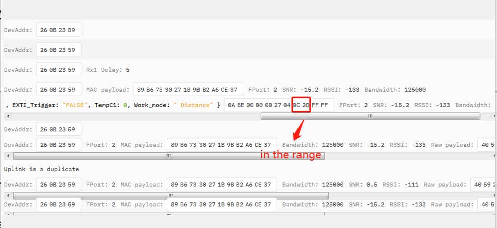
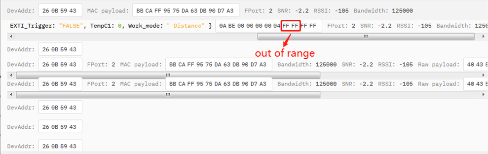
2.3.3.8 Ultrasonic Sensor
The LSN50 v1.5 firmware supports ultrasonic sensor (with AT+MOD=2) such as SEN0208 from DF-Robot. This Fundamental Principles of this sensor can be found at this link: https://wiki.dfrobot.com/Weather_-_proof_Ultrasonic_Sensor_with_Separate_Probe_SKU___SEN0208
The LSN50 detects the pulse width of the sensor and converts it to mm output. The accuracy will be within 1 centimeter. The usable range (the distance between the ultrasonic probe and the measured object) is between 24cm and 600cm.
The picture below shows the connection:

Connect to the LSN50 and run AT+MOD=2 to switch to ultrasonic mode (ULT).
The ultrasonic sensor uses the 8th and 9th byte for the measurement value.
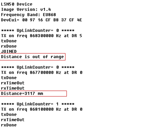
Example:
Distance: Read: 0C2D(Hex) = 3117(D) Value: 3117 mm=311.7 cm


You can see the serial output in ULT mode as below:
In TTN V3 server:
2.3.3.9 Battery Output - BAT pin
The BAT pin of SN50v3 is connected to the Battery directly. If users want to use BAT pin to power an external sensor. User need to make sure the external sensor is of low power consumption. Because the BAT pin is always open. If the external sensor is of high power consumption. the battery of SN50v3-LB will run out very soon.
2.3.3.10 +5V Output
SN50v3 will enable +5V output before all sampling and disable the +5v after all sampling.
The 5V output time can be controlled by AT Command.
AT+5VT=1000
Means set 5V valid time to have 1000ms. So the real 5V output will actually have 1000ms + sampling time for other sensors.
By default the AT+5VT=500. If the external sensor which require 5v and require more time to get stable state, user can use this command to increase the power ON duration for this sensor.
2.3.3.11 BH1750 Illumination Sensor
MOD=1 support this sensor. The sensor value is in the 8th and 9th bytes.
2.3.3.12 Working MOD
The working MOD info is contained in the Digital in & Digital Interrupt byte (7th Byte).
User can use the 3rd ~ 7th bit of this byte to see the working mod:
Case 7th Byte >> 2 & 0x1f:
- 0: MOD1
- 1: MOD2
- 2: MOD3
- 3: MOD4
- 4: MOD5
- 5: MOD6
2.4 Payload Decoder file
In TTN, use can add a custom payload so it shows friendly reading
In the page Applications --> Payload Formats --> Custom --> decoder to add the decoder from:
https://github.com/dragino/dragino-end-node-decoder/tree/main/LSN50v2-S31%26S31B
2.5 Frequency Plans
The SN50v3-LB uses OTAA mode and below frequency plans by default. If user want to use it with different frequency plan, please refer the AT command sets.
http://wiki.dragino.com/xwiki/bin/view/Main/End%20Device%20Frequency%20Band/
3. Configure SN50v3-LB
3.1 Configure Methods
SN50v3-LB supports below configure method:
- AT Command via Bluetooth Connection (Recommended): BLE Configure Instruction.
- AT Command via UART Connection : See UART Connection.
- LoRaWAN Downlink. Instruction for different platforms: See IoT LoRaWAN Server section.
3.2 General Commands
These commands are to configure:
- General system settings like: uplink interval.
- LoRaWAN protocol & radio related command.
They are same for all Dragino Devices which support DLWS-005 LoRaWAN Stack. These commands can be found on the wiki:
http://wiki.dragino.com/xwiki/bin/view/Main/End%20Device%20AT%20Commands%20and%20Downlink%20Command/
3.3 Commands special design for SN50v3-LB
These commands only valid for S31x-LB, as below:
3.3.1 Set Transmit Interval Time
Feature: Change LoRaWAN End Node Transmit Interval.
AT Command: AT+TDC
| Command Example | Function | Response |
|---|---|---|
| AT+TDC=? | Show current transmit Interval | 30000 |
| AT+TDC=60000 | Set Transmit Interval | OK |
Downlink Command: 0x01
Format: Command Code (0x01) followed by 3 bytes time value.
If the downlink payload=0100003C, it means set the END Node's Transmit Interval to 0x00003C=60(S), while type code is 01.
- Example 1: Downlink Payload: 0100001E // Set Transmit Interval (TDC) = 30 seconds
- Example 2: Downlink Payload: 0100003C // Set Transmit Interval (TDC) = 60 seconds
3.3.2 Get Device Status
Send a LoRaWAN downlink to ask device send Alarm settings.
Downlink Payload: 0x26 01
Sensor will upload Device Status via FPORT=5. See payload section for detail.
3.3.7 Set Interrupt Mode
Feature, Set Interrupt mode for GPIO_EXIT.
AT Command: AT+INTMOD
| Command Example | Function | Response |
|---|---|---|
| AT+INTMOD=? | Show current interrupt mode | 0 |
| AT+INTMOD=2 | Set Transmit Interval | OK |
Downlink Command: 0x06
Format: Command Code (0x06) followed by 3 bytes.
This means that the interrupt mode of the end node is set to 0x000003=3 (rising edge trigger), and the type code is 06.
- Example 1: Downlink Payload: 06000000 // Turn off interrupt mode
- Example 2: Downlink Payload: 06000003 // Set the interrupt mode to rising edge trigger
4. Battery & Power Consumption
SN50v3-LB use ER26500 + SPC1520 battery pack. See below link for detail information about the battery info and how to replace.
Battery Info & Power Consumption Analyze .
5. OTA Firmware update
User can change firmware SN50v3-LB to:
- Change Frequency band/ region.
- Update with new features.
- Fix bugs.
Firmware and changelog can be downloaded from : Firmware download link
Methods to Update Firmware:
- (Recommanded way) OTA firmware update via wireless: http://wiki.dragino.com/xwiki/bin/view/Main/Firmware%20OTA%20Update%20for%20Sensors/
- Update through UART TTL interface.Instruction.
6. FAQ
7. Order Info
Part Number: SN50v3-LB-XX-YY
XX: The default frequency band
- AS923: LoRaWAN AS923 band
- AU915: LoRaWAN AU915 band
- EU433: LoRaWAN EU433 band
- EU868: LoRaWAN EU868 band
- KR920: LoRaWAN KR920 band
- US915: LoRaWAN US915 band
- IN865: LoRaWAN IN865 band
- CN470: LoRaWAN CN470 band
YY: Hole Option
- 12: With M12 waterproof cable hole
- 16: With M16 waterproof cable hole
- 20: With M20 waterproof cable hole
- NH: No Hole
8. Packing Info
Package Includes:
- SN50v3-LB LoRaWAN Generic Node
Dimension and weight:
- Device Size: cm
- Device Weight: g
- Package Size / pcs : cm
- Weight / pcs : g
9. Support
- Support is provided Monday to Friday, from 09:00 to 18:00 GMT+8. Due to different timezones we cannot offer live support. However, your questions will be answered as soon as possible in the before-mentioned schedule.
- Provide as much information as possible regarding your enquiry (product models, accurately describe your problem and steps to replicate it etc) and send a mail to support@dragino.com