LT-22222-L -- LoRa I/O Controller User Manual
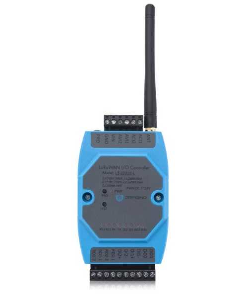
Table of Contents:
- 1. Introduction
- 2. Assembling the device
- 3. Registering LT-22222-L with a LoRaWAN Network Server
- 3.1 Prerequisites
- 3.2 The Things Stack
- 3.3 Working Modes and Uplink Payload formats
- 3.4 Configure LT-22222-L via AT Commands or Downlinks
- 3.4.1 Common commands
- 3.4.2 Sensor-related commands
- 3.4.2.1 Set Transmit/Uplink Interval
- 3.4.2.2 Set the Working Mode (AT+MOD)
- 3.4.2.3 Request an uplink from the device
- 3.4.2.4 Enable/Disable Trigger Mode
- 3.4.2.5 Request trigger settings
- 3.4.2.6 Enable/Disable DI1/DI2/DI3 as a trigger
- 3.4.2.7 Trigger1 – Set DI1 or DI3 as a trigger
- 3.4.2.8 Trigger2 – Set DI2 as a trigger
- 3.4.2.9 Trigger – Set AC (current) as a trigger
- 3.4.2.10 Trigger – Set AV (voltage) as trigger
- 3.4.2.11 Trigger – Set the minimum interval
- 3.4.2.12 DO -- Control Digital Output DO1/DO2/DO3
- 3.4.2.13 DO -- Control Digital Output DO1/DO2/DO3 with time control
- 3.4.2.14 Relay -- Control Relay Output RO1/RO2
- 3.4.2.15 Relay -- Control Relay Output RO1/RO2 with time control
- 3.4.2.16 Counting -- Voltage threshold counting
- 3.4.2.17 Counting -- Pre-configure the Count Number
- 3.4.2.18 Counting -- Clear Counting
- 3.4.2.19 Set the save intervals of the counting results, RO (Relay Output), and DO (Digital Output) states
- 3.4.2.20 Reset saved RO and DO states
- 3.4.2.21 Encrypted payload
- 3.4.2.22 Get sensor value
- 3.4.2.23 Resetting the downlink packet count
- 3.4.2.24 When the limit bytes are exceeded, upload in batches
- 3.4.2.25 Copy downlink to uplink
- 3.4.2.26 Query firmware version, frequency band, subband, and TDC time
- 3.5 Integrating with ThingsEye.io
- 3.6 Interface Details
- 3.7 LED Indicators
- 4. Using AT Commands
- 5. Case Study
- 6. FAQ
- 6.1 How to update the firmware?
- 6.2 How to change the LoRaWAN frequency band/region?
- 6.3 How to set up LT-22222-L to work with a Single Channel Gateway, such as LG01/LG02?
- 6.4 How to change the uplink interval?
- 6.5 Can I see the counting event in the serial output?
- 6.6 Can I use point-to-point communication with LT-22222-L?
- 6.7 Why does the relay output default to an open relay after the LT-22222-L is powered off?
- 6.8 Can I set up LT-22222-L as an NC (Normally Closed) relay?
- 6.9 Can the LT-22222-L save the RO state?
- 6.10 Why does the LT-22222-L always report 15.585V when measuring the AVI?
- 7. Troubleshooting
- 8. Ordering information
- 9. Package information
- 10. Support
- 11. Reference
1. Introduction
1.1 What is the LT-22222-L I/O Controller?
The Dragino LT-22222-L I/O Controller is an advanced LoRaWAN end device designed to provide seamless wireless long-range connectivity with various I/O options, including analog current and voltage inputs, digital inputs and outputs, and relay outputs.
The LT-22222-L I/O Controller simplifies and enhances I/O monitoring and controlling. It is ideal for professional applications in wireless sensor networks, including irrigation systems, smart metering, smart cities, building automation, and more. These controllers are designed for easy, cost-effective deployment using LoRa wireless technology.
With the LT-22222-L I/O Controller, users can transmit data over ultra-long distances with low power consumption using LoRa, a spread-spectrum modulation technique derived from chirp spread spectrum (CSS) technology that operates on license-free ISM bands.
You can connect the LT-22222-L I/O Controller to a LoRaWAN network service provider in several ways:
- If there is public LoRaWAN network coverage in the area where you plan to install the device (e.g., The Things Stack Community Network), you can select a network and register the LT-22222-L I/O controller with it.
- If there is no public LoRaWAN coverage in your area, you can set up a LoRaWAN gateway, or multiple gateways, and connect them to a LoRaWAN network server to create adequate coverage. Then, register the LT-22222-L I/O controller with this network.
- Setup your own private LoRaWAN network.
The network diagram below illustrates how the LT-22222-L communicates with a typical LoRaWAN network.

1.2 Specifications
Hardware System:
- STM32L072xxxx MCU
- SX1276/78 Wireless Chip
- Power Consumption:
- Idle: 4mA@12V
- 20dB Transmit: 34mA@12V
- Operating Temperature: -40 ~ 85 Degrees, No Dew
Interface for Model: LT22222-L:
- 2 x Digital dual direction Input (Detect High/Low signal, Max: 50V, or 220V with optional external resistor)
- 2 x Digital Output (NPN output. Max pull-up voltage 36V,450mA)
- 2 x Relay Output (5A@250VAC / 30VDC)
- 2 x 0~20mA Analog Input (res:0.01mA)
- 2 x 0~30V Analog Input (res:0.01V)
- Power Input 7~ 24V DC.
LoRa Spec:
- Frequency Range:
- Band 1 (HF): 862 ~ 1020 MHz
- Band 2 (LF): 410 ~ 528 MHz
- 168 dB maximum link budget.
- +20 dBm - 100 mW constant RF output vs.
- +14 dBm high-efficiency PA.
- Programmable bit rate up to 300 kbps.
- High sensitivity: down to -148 dBm.
- Bullet-proof front end: IIP3 = -12.5 dBm.
- Excellent blocking immunity.
- Low RX current of 10.3 mA, 200 nA register retention.
- Fully integrated synthesizer with a resolution of 61 Hz.
- FSK, GFSK, MSK, GMSK, LoRaTM and OOK modulation.
- Built-in bit synchronizer for clock recovery.
- Preamble detection.
- 127 dB Dynamic Range RSSI.
- Automatic RF Sense and CAD with ultra-fast AFC.
- Packet engine up to 256 bytes with CRC.
1.3 Features
- LoRaWAN Class A & Class C modes
- Optional Customized LoRa Protocol
- Frequency Bands: CN470/EU433/KR920/US915/EU868/AS923/AU915/RU864/IN865/MA869
- AT Commands to change parameters
- Remotely configure parameters via LoRaWAN Downlink
- Firmware upgradable via program port
- Counting
1.4 Applications
- Smart buildings & home automation
- Logistics and supply chain management
- Smart metering
- Smart agriculture
- Smart cities
- Smart factory
1.5 Hardware Variants
| Model | Photo | Description |
| LT-33222-L |
|
|

2. Assembling the device
2.1 Connecting the antenna
Connect the LoRa antenna to the antenna connector, ANT, located on the top right side of the device, next to the upper screw terminal block. Secure the antenna by tightening it clockwise.
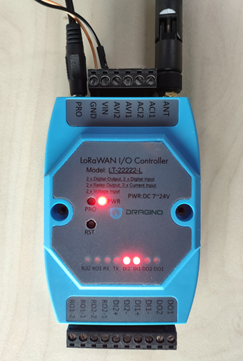
2.2 Terminals
The LT-22222-L has two screw terminal blocks. The upper screw terminal block has 6 screw terminals and the lower screw terminal block has 10 screw terminals.
Upper screw terminal block (from left to right):
| Screw Terminal | Function |
|---|---|
| GND | Ground |
| VIN | Input Voltage |
| AVI2 | Analog Voltage Input Terminal 2 |
| AVI1 | Analog Voltage Input Terminal 1 |
| ACI2 | Analog Current Input Terminal 2 |
| ACI1 | Analog Current Input Terminal 1 |
Lower screw terminal block (from left to right):
| Screw Terminal | Function |
|---|---|
| RO1-2 | Relay Output 1 |
| RO1-1 | Relay Output 1 |
| RO2-2 | Relay Output 2 |
| RO2-1 | Relay Output 2 |
| DI2+ | Digital Input 2 |
| DI2- | Digital Input 2 |
| DI1+ | Digital Input 1 |
| DI1- | Digital Input 1 |
| DO2 | Digital Output 2 |
| DO1 | Digital Output 1 |
2.3 Connecting LT-22222-L to a Power Source
The LT-22222-L I/O Controller can be powered by a 7–24V DC power source. Connect your power supply’s positive wire to the VIN and the negative wire to the GND screw terminals. The power indicator (PWR) LED will turn on when the device is properly powered.
3. Registering LT-22222-L with a LoRaWAN Network Server
The LT-22222-L supports both OTAA (Over-the-Air Activation) and ABP (Activation By Personalization) methods to activate with a LoRaWAN Network Server. However, OTAA is the most secure method for activating a device with a LoRaWAN Network Server. OTAA regenerates session keys upon initial registration and regenerates new session keys after any subsequent reboots. By default, the LT-22222-L is configured to operate in LoRaWAN Class C mode.
3.1 Prerequisites
The LT-22222-L comes with device registration information such as DevEUI, AppEUI, and AppKey which allows you to register it with a LoRaWAN network. This registration information can be found on a sticker that can be found inside the package. Please keep the registration information sticker in a safe place for future reference.
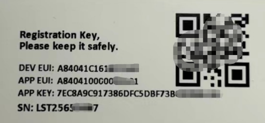
The following subsections explain how to register the LT-22222-L with different LoRaWAN network server providers.
3.2 The Things Stack
This section guides you through how to register your LT-22222-L with The Things Stack Sandbox.
The network diagram below illustrates the connection between the LT-22222-L and The Things Stack, as well as how the data can be integrated with the ThingsEye IoT platform.

3.2.1 Setting up
- Sign up for a free account with The Things Stack Sandbox if you do not have one yet.
- Log in to your The Things Stack Sandbox account.
- Create an application with The Things Stack if you do not have one yet (E.g., dragino-docs).
- Go to your application's page and click on the End devices in the left menu.
- On the End devices page, click on + Register end device. Two registration options are available:
3.2.1.1 Using the LoRaWAN Device Repository
- On the Register end device page:
- Select the option Select the end device in the LoRaWAN Device Repository under Input method.
- Select the End device brand, Model, Hardware version, Firmware version, and Profile (Region) from the respective dropdown lists.
- End device brand: Dragino Technology Co., Limited
- Model: LT22222-L I/O Controller
- Hardware ver: Unknown
- Firmware ver: 1.6.0
- Profile (Region): Select the region that matches your device.
- Select the Frequency plan that matches your device from the Frequency plan dropdown list.

- Register end device page continued...
- Enter the AppEUI in the JoinEUI field and click the Confirm button. If The Things Stack accepts the JoinEUI you provided, it will display the message 'This end device can be registered on the network'.
- In the DevEUI field, enter the DevEUI.
- In the AppKey field, enter the AppKey.
- In the End device ID field, enter a unique name for your LT-22222-L within this application.
- Under After registration, select the View registered end device option.
- Click Register end device button.

- You will be navigated to the Device overview page.

3.2.1.2 Adding device manually
- On the Register end device page:
- Select the option Enter end device specifies manually under Input method.
- Select the Frequency plan that matches your device from the Frequency plan dropdown list.
- Select the LoRaWAN version as LoRaWAN Specification 1.0.3
- Select the Regional Parameters version as RP001 Regional Parameters 1.0.3 revision A
- Click Show advanced activation, LoRaWAN class and cluster settings link to expand the hidden section.
- Select the option Over the air activation (OTAA) under the Activation mode.
- Select Class C (Continuous) from the Additional LoRaWAN class capabilities dropdown list.

- Register end device page continued...
- Enter the AppEUI in the JoinEUI field and click the Confirm button. If The Things Stack accepts the JoinEUI you provided, it will display the message 'This end device can be registered on the network'
- In the DevEUI field, enter the DevEUI.
- In the AppKey field, enter the AppKey.
- In the End device ID field, enter a unique name for your LT-22222-N within this application.
- Under After registration, select the View registered end device option.
- Click the Register end device button.

You will be navigated to the Device overview page.
3.2.2 Joining
On the end device's page (in this case, lt-22222-l), click on Live data tab. The Live data panel for your device will display. Initially, it is blank.
Now power on your LT-22222-L. The TX LED will fast-blink 5 times which means the LT-22222-L will enter the work mode and start to join The Things Stack network server. The TX LED will be on for 5 seconds after joining the network. In the Live data panel, you can see the join-request and join-accept messages exchanged between the device and the network server.

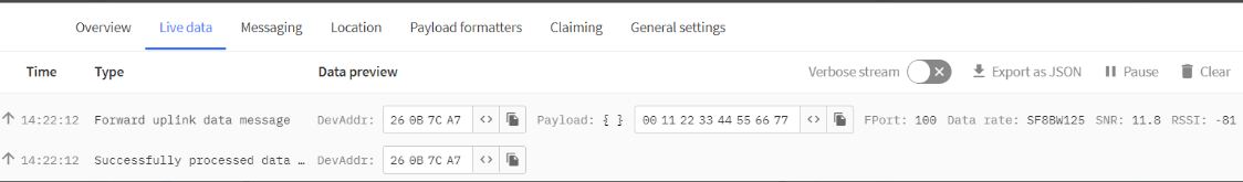
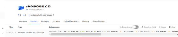
3.2.3 Uplinks
After successfully joining, the device will send its first uplink data message to The Things Stack application it belongs to (in this example, it is dragino-docs). When the LT-22222-L sends an uplink message to the server, the TX LED turns on for 1 second. By default, you will receive an uplink data message from the device every 10 minutes.
Click on one of the Forward uplink data messages to see its payload content. The payload content is encapsulated within the decode_payload {} JSON object.

If you can't see the decoded payload, it is because you haven't added the uplink formatter code. To add the uplink formatter code, select Applications > [your application] > End devices > [your end device] > Payload formatters > Uplink. Then select Use Device repository formatters for the Formatter type dropdown. Click the Save changes button to apply the changes.

We have written a payload formatter that resolves some decoding issues present in The Things Stack Device Repository payload formatter. You can add it under the Custom JavaScript formatter. It can be found here:

3.2.4 Downlinks
When the LT-22222-L receives a downlink message from the LoRaWAN Network Server, the RX LED turns on for 1 second.
3.3 Working Modes and Uplink Payload formats
The LT-22222-L has 5 working modes. It also has an interrupt/trigger mode for different types of applications that can be used together with any working mode as an additional feature. The default mode is MOD1 and you can switch between these modes using AT commands.
- MOD1: (default mode/factory set): 2ACI + 2AVI + DI + DO + RO
- MOD2: Double DI Counting + DO + RO
- MOD3: Single DI Counting + 2 x ACI + DO + RO
- MOD4: Single DI Counting + 1 x Voltage Counting + DO + RO
- MOD5: Single DI Counting + 2 x AVI + 1 x ACI + DO + RO
- ADDMOD6: Trigger Mode, Optional, used together with MOD1 ~ MOD5
The uplink messages are sent over LoRaWAN FPort=2. By default, an uplink message is sent every 10 minutes.
3.3.1 AT+MOD=1, 2ACI+2AVI
This is the default mode.
The uplink payload is 11 bytes long.
| Size(bytes) | 2 | 2 | 2 | 2 | 1 | 1 | 1 |
| Value | AVI1 voltage | AVI2 voltage | ACI1 Current | ACI2 Current | DIDORO* | Reserve | MOD |
* DIDORO is a combination of RO1, RO2, DI3, DI2, DI1, DO3, DO2 and DO1, and its size is1 byte long as shown below.
| bit 7 | bit 6 | bit 5 | bit 4 | bit 3 | bit 2 | bit 1 | bit 0 |
| RO1 | RO2 | DI2 | DI1 | DO2 | DO1 |
- RO is for the relay. ROx=1: CLOSED, ROx=0 always OPEN.
- DI is for digital input. DIx=1: HIGH or FLOATING, DIx=0: LOW.
- DO is for reverse digital output. DOx=1: LOW, DOx=0: HIGH or FLOATING.
Note: DI3 and DO3 bits are not valid for LT-22222-L
For example, if the payload is: 
The interface values can be calculated as follows:
AVI1 channel voltage is 0x04AB/1000=1195(DEC)/1000=1.195V
AVI2 channel voltage is 0x04AC/1000=1.196V
ACI1 channel current is 0x1310/1000=4.880mA
ACI2 channel current is 0x1300/1000=4.864mA
The last byte 0xAA= 10101010(b) means,
- [1] The RO1 relay channel is CLOSED, and the RO1 LED is ON.
- [0] The RO2 relay channel is OPEN, and the RO2 LED is OFF.
- [1] DI3 - not used for LT-22222-L.
- [0] DI2 channel input is LOW, and the DI2 LED is OFF.
- [1] DI1 channel input state:
- DI1 is FLOATING when no sensor is connected between DI1+ and DI1-.
- DI1 is HIGH when a sensor is connected between DI1- and DI1+ and the sensor is ACTIVE.
- DI1 LED is ON in both cases.
- [0] DO3 - not used for LT-22222-L.
- [1] DO2 channel output is LOW, and the DO2 LED is ON.
- [0] DO1 channel output state:
- DO1 is FLOATING when there is no load between DO1 and V+.
- DO1 is HIGH and there is a load between DO1 and V+.
- DO1 LED is OFF in both cases.
Reserve = 0
MOD = 1
3.3.2 AT+MOD=2, (Double DI Counting)
For LT-22222-L: In this mode, DI1 and DI2 are used as counting pins.
The uplink payload is 11 bytes long.
Note:The maximum count depends on the bytes it is.
The maximum count for four bytes is FFFFFFFF (hex) = 4294967295 (dec).
It starts counting again when it reaches the maximum value.
| Size(bytes) | 4 | 4 | 1 | 1 | 1 |
| Value | COUNT1 | COUNT2 | DIDORO* | Reserve | MOD |
*DIDORO is a combination of RO1, RO2, FIRST, Reserve, Reserve, DO3, DO2 and DO1, and its size is 1 byte long as shown below.
| bit 7 | bit 6 | bit 5 | bit 4 | bit 3 | bit 2 | bit 1 | bit 0 |
| RO1 | RO2 | FIRST | Reserve | Reserve | DO2 | DO1 |
- RO is for the relay. ROx=1: CLOSED, ROx=0 always OPEN.
- FIRST: Indicates that this is the first packet after joining the network.
- DO is for reverse digital output. DOx=1: LOW, DOx=0: HIGH or FLOATING.
Note: DO3 bit is not valid for LT-22222-L
To activate this mode, run the following AT commands:
AT Commands for counting:
For LT22222-L:
AT+TRIG1=0,100 (sets the DI1 port to trigger on a LOW level. The valid signal duration is 100ms)
AT+TRIG1=1,100 (sets the DI1 port to trigger on a HIGH level. The valid signal duration is 100ms)
AT+TRIG2=0,100 (sets the DI2 port to trigger on a LOW level. The valid signal duration is 100ms)
AT+TRIG2=1,100 (sets the DI2 port to trigger on a HIGH level. The valid signal duration is 100ms)
AT+SETCNT=1,60 (sets the COUNT1 value to 60)
AT+SETCNT=2,60 (sets the COUNT2 value to 60)
3.3.3 AT+MOD=3, Single DI Counting + 2 x ACI
Note: The maximum count depends on the bytes it is.
The maximum count for four bytes is FFFFFFFF (hex) = 4294967295 (dec).
It starts counting again when it reaches the maximum value.
LT22222-L: In this mode, the DI1 is used as a counting pin.
| Size(bytes) | 4 | 2 | 2 | 1 | 1 | 1 |
| Value | COUNT1 | ACI1 Current | ACI2 Current | DIDORO* | Reserve | MOD |
*DIDORO is a combination of RO1, RO2, DI3, DI2, DI1, DO3, DO2 and DO1, for a total of 1 byte, as shown below.
| bit 7 | bit 6 | bit 5 | bit 4 | bit 3 | bit 2 | bit 1 | bit 0 |
| RO1 | RO2 | FIRST | Reserve | Reserve | DO2 | DO1 |
- RO is for the relay. ROx=1: closed, ROx=0 always open.
- FIRST: Indicates that this is the first packet after joining the network.
- DO is for reverse digital output. DOx=1: output low, DOx=0: high or floating.
Note: DO3 bit is not valid for LT-22222-L.
To activate this mode, run the following AT commands:
AT Commands for counting:
The AT Commands for counting are similar to the MOD2 Counting Commands.
3.3.4 AT+MOD=4, Single DI Counting + 1 x Voltage Counting
Note:The maximum count depends on the bytes it is.
The maximum count for four bytes is FFFFFFFF (hex) = 4294967295 (dec).
It starts counting again when it reaches the maximum value.
LT22222-L: In this mode, the DI1 is used as a counting pin.
The AVI1 is also used for counting. It monitors the voltage and checks it every 60 seconds. If the voltage is higher or lower than VOLMAX mV, the AVI1 count increases by 1, allowing AVI1 counting to be used to measure a machine's working hours.
| Size(bytes) | 4 | 4 | 1 | 1 | 1 |
| Value | COUNT1 | AVI1 Counting | DIDORO* | Reserve | MOD |
DIDORO is a combination of RO1, RO2, DI3, DI2, DI1, DO3, DO2 and DO1, for a total of 1 byte, as shown below.
| bit 7 | bit 6 | bit 5 | bit 4 | bit 3 | bit 2 | bit 1 | bit 0 |
| RO1 | RO2 | FIRST | Reserve | Reserve | DO2 | DO1 |
- RO is for the relay. ROx=1: closed, ROx=0 always open.
- FIRST: Indicates that this is the first packet after joining the network.
- DO is for reverse digital output. DOx=1: output low, DOx=0: high or floating.
Note: DO3 bit is not valid for LT-22222-L.
To activate this mode, run the following AT commands:
AT Commands for counting are similar to the MOD2 Counting Commands.
In addition to that, below are the commands for AVI1 Counting:
AT+SETCNT=3,60 (Sets AVI1 Count to 60)
AT+VOLMAX=20000 (If the AVI1 voltage is higher than VOLMAX (20000mV =20V), the counter increases by 1)
AT+VOLMAX=20000,0 (If the AVI1 voltage is lower than VOLMAX (20000mV =20V), counter increases by 1)
AT+VOLMAX=20000,1 (If the AVI1 voltage is higher than VOLMAX (20000mV =20V), counter increases by 1)
3.3.5 AT+MOD=5, Single DI Counting + 2 x AVI + 1 x ACI
Note:The maximum count depends on the bytes it is.
The maximum count for four bytes is FFFF (hex) = 65535 (dec).
It starts counting again when it reaches the maximum value.
LT22222-L: In this mode, the DI1 is used as a counting pin.
| Size(bytes) | 2 | 2 | 2 | 2 | 1 | 1 | 1 |
| Value | AVI1 voltage | AVI2 voltage | ACI1 Current | COUNT1 | DIDORO* | Reserve | MOD |
DIDORO is a combination of RO1, RO2, DI3, DI2, DI1, DO3, DO2 and DO1, for a total of 1 byte, as shown below.
| bit 7 | bit 6 | bit 5 | bit 4 | bit 3 | bit 2 | bit 1 | bit 0 |
| RO1 | RO2 | FIRST | Reserve | Reserve | DO3 | DO2 | DO1 |
- RO is for the relay. ROx=1: closed, ROx=0 always open.
- FIRST: Indicates that this is the first packet after joining the network.
DO is for reverse digital output. DOx=1: output low, DOx=0: high or floating.
Note: DO3 bit is not valid for LT-22222-L.
To activate this mode, run the following AT commands:
Other AT Commands for counting are similar to the MOD2 Counting Commands.
3.3.6 AT+ADDMOD=6 (Trigger Mode, Optional)
This mode is optional and intended for trigger purposes. It can operate alongside with other modes.
For example, if you configure the following commands:
- AT+MOD=1 --> Sets the default working mode
- AT+ADDMOD6=1 --> Enables trigger mode
The LT-22222-L will continuously monitor AV1, AV2, AC1, and AC2 every 5 seconds. It will send uplink packets in two cases:
- Periodic uplink: Based on TDC time. The payload is the same as in normal mode (MOD=1 as set above). These are unconfirmed uplinks.
Trigger uplink: sent when a trigger condition is met. In this case, LT will send two packets
- The first uplink uses the payload specified in trigger mode (MOD=6).
- The second packet uses the normal mode payload (MOD=1 as set above). Both are confirmed uplinks.
AT Commands to set Trigger Conditions:
Trigger based on voltage:
Format: AT+AVLIM=<AV1_LIMIT_LOW>,< AV1_LIMIT_HIGH>,<AV2_LIMIT_LOW>,< AV2_LIMIT_HIGH>
Example:
AT+AVLIM=3000,6000,0,2000 (triggers an uplink if AVI1 voltage is lower than 3V or higher than 6V, or if AV2 voltage is higher than 2V)
AT+AVLIM=5000,0,0,0 (triggers an uplink if AVI1 voltage is lower than 5V. Use 0 for parameters that are not in use)
Trigger based on current:
Format: AT+ACLIM=<AC1_LIMIT_LOW>,< AC1_LIMIT_HIGH>,<AC2_LIMIT_LOW>,< AC2_LIMIT_HIGH>
Example:
AT+ACLIM=10000,15000,0,0 (triggers an uplink if AC1 current is lower than 10mA or higher than 15mA)
Trigger based on DI status:
DI status triggers Flag.
Format: AT+DTRI=<DI1_TIRGGER_FlAG>,< DI2_TIRGGER_FlAG >
Example:
AT+ DTRI =1,0 (Enable DI1 trigger / disable DI2 trigger)
LoRaWAN Downlink Commands for Setting the Trigger Conditions:
Type Code: 0xAA. Downlink command same as AT Command AT+AVLIM, AT+ACLIM
Format: AA xx yy1 yy1 yy2 yy2 yy3 yy3 yy4 yy4
AA: Type Code for this downlink Command:
xx: 0: Limit for AV1 and AV2; 1: limit for AC1 and AC2; 2: DI1and DI2 trigger enable/disable.
yy1 yy1: AC1 or AV1 LOW limit or DI1/DI2 trigger status.
yy2 yy2: AC1 or AV1 HIGH limit.
yy3 yy3: AC2 or AV2 LOW limit.
Yy4 yy4: AC2 or AV2 HIGH limit.
Example 1: AA 00 13 88 00 00 00 00 00 00
Same as AT+AVLIM=5000,0,0,0 (triggers an uplink if AVI1 voltage is lower than 5V. Use 0s for parameters that are not in use)
Example 2: AA 02 01 00
Same as AT+ DTRI =1,0 (Enable DI1 trigger / disable DI2 trigger)
Trigger Settings Payload Explanation:
MOD6 Payload: a total of 11 bytes
| Size(bytes) | 1 | 1 | 1 | 6 | 1 | 1 |
| Value | TRI_A FLAG | TRI_A Status | TRI_DI FLAG+STA | Reserve | Enable/Disable MOD6 | MOD(6) |
TRI FLAG1 is a combination to show if the trigger is set for this part. Total 1 byte as below.
| bit 7 | bit 6 | bit 5 | bit 4 | bit 3 | bit 2 | bit 1 | bit 0 |
AV1_LOW | AV1_HIGH | AV2_LOW | AV2_HIGH | AC1_LOW | AC1_HIGH | AC2_LOW | AC2_HIGH |
- Each bit shows if the corresponding trigger has been configured.
Example:
10100000: This means the system is configured to use the triggers AV1_LOW and AV2_LOW.
TRI Status1 is a combination to show which condition is triggered. Total 1 byte as below.
| bit 7 | bit 6 | bit 5 | bit 4 | bit 3 | bit 2 | bit 1 | bit 0 |
AV1_LOW | AV1_HIGH | AV2_LOW | AV2_HIGH | AC1_LOW | AC1_HIGH | AC2_LOW | AC2_HIGH |
- Each bit shows which status has been triggered on this uplink.
Example:
10000000: The uplink is triggered by AV1_LOW, indicating that the voltage is too low.
TRI_DI FLAG+STA is a combination to show which condition is triggered. Total 1 byte as below.
| bit 7 | bit 6 | bit 5 | bit 4 | bit 3 | bit 2 | bit 1 | bit 0 |
| N/A | N/A | N/A | N/A | DI2_STATUS | DI2_FLAG | DI1_STATUS | DI1_FLAG |
- Each bit shows which status has been triggered on this uplink.
Example:
00000111: This means both DI1 and DI2 triggers are enabled, and this packet is triggered by DI1.
00000101: This means both DI1 and DI2 triggers are enabled.
Enable/Disable MOD6 : 0x01: MOD6 is enabled. 0x00: MOD6 is disabled.
Downlink command to poll/request MOD6 status:
AB 06
When the device receives this command, it will send the MOD6 payload.
3.3.7 Payload Decoder
Decoder for TTN/loraserver/ChirpStack: https://github.com/dragino/dragino-end-node-decoder
3.4 Configure LT-22222-L via AT Commands or Downlinks
You can configure LT-22222-L I/O Controller via AT Commands or LoRaWAN Downlinks.
There are two types of commands:
- Common commands:
- Sensor-related commands:
3.4.1 Common commands
These are available for each sensor and include actions such as changing the uplink interval or resetting the device. For firmware v1.5.4, you can find the supported common commands under: End Device AT Commands and Downlink Commands.
3.4.2 Sensor-related commands
These commands are specially designed for the LT-22222-L. Commands can be sent to the device using options such as an AT command or a LoRaWAN downlink payload.
3.4.2.1 Set Transmit/Uplink Interval
Sets the uplink interval of the device. The default uplink transmission interval is 10 minutes.
AT command
| Command | AT+TDC=<time> |
| Parameters | time : uplink interval in milliseconds |
| Get | AT+TDC=? |
| Response | current uplink interval OK |
| Set | AT+TDC=<time> |
| Response | OK |
| Example | AT+TDC=30000 Sets the uplink interval to 30 seconds (30000 milliseconds) |
Downlink payload
| Payload | <prefix><time> |
| Parameters | prefix : 0x01 time : uplink interval in seconds, represented by 3 bytes in hexadecimal. |
| Example | 01 00 00 1E Sets the uplink interval to 30 seconds Conversion: 30 (dec) = 00 00 1E (hex) See RapidTables
|

3.4.2.2 Set the Working Mode (AT+MOD)
Sets the working mode.
AT command
| Command | AT+MOD=<working_mode> |
| Parameters | working_mode : 1 = (Default mode/factory set): 2ACI + 2AVI + DI + DO + RO 2 = Double DI Counting + DO + RO 3 = Single DI Counting + 2 x ACI + DO + RO 4 = Single DI Counting + 1 x Voltage Counting + DO + RO 5 = Single DI Counting + 2 x AVI + 1 x ACI + DO + RO 6 = Trigger Mode, Optional, used together with MOD1 ~ MOD5 |
| Get | AT+MOD=? |
| Response | Current working mode OK |
| Set | AT+MOD=<working_mode> |
| Response | Attention:Take effect after ATZ OK |
| Example | AT+MOD=2 Sets the device to working mode 2 (Double DI Counting + DO + RO) |
Downlink payload
| Payload | <prefix><working_mode> |
| Parameters | prefix : 0x0A working_mode : Working mode, represented by 1 byte in hexadecimal. |
| Example | 0A 02 Sets the device to working mode 2 (Double DI Counting + DO + RO) |
3.4.2.3 Request an uplink from the device
Requests an uplink from LT-22222-L. The content of the uplink payload varies based on the device's current working mode.
AT command
There is no AT Command available for this feature.
Downlink payload
| Payload | <prefix>FF |
| Parameters | prefix : 0x08 |
| Example | 08 FF Requests an uplink from LT-22222-L. |
3.4.2.4 Enable/Disable Trigger Mode
Enable or disable the trigger mode for the current working mode (see also ADDMOD6).
AT Command
| Command | AT+ADDMOD6=<enable/disable trigger_mode> |
| Response | |
| Parameters | enable/disable trigger_mode : 1 = enable trigger mode 0 = disable trigger mode |
| Example | AT+ADDMOD6=1 Enable trigger mode for the current working mode |
Downlink payload
| Payload | <prefix><enable/disable trigger_mode> |
| Parameters | prefix : 0x0A 06 (two bytes in hexadecimal) enable/disable trigger_mode : enable (1) or disable (0), represented by 1 byte in hexadecimal. |
| Example | 0A 06 01 Enable trigger mode for the current working mode |
3.4.2.5 Request trigger settings
Requests the trigger settings.
AT Command:
There is no AT Command available for this feature.
Downlink Payload
| Payload | <prefix> |
| Parameters | prefix : AB 06 (two bytes in hexadecimal) |
| Example | AB 06 Uplink the trigger settings. |
3.4.2.6 Enable/Disable DI1/DI2/DI3 as a trigger
Enable or disable DI1/DI2/DI3 as a trigger.
AT Command
| Command | AT+DTRI=<DI1_trigger>,<DI2_trigger> |
| Response | |
| Parameters | DI1_trigger: 1 = enable DI1 trigger 0 = disable DI1 trigger DI2 _trigger 1 = enable DI2 trigger 0 = disable DI2 trigger |
| Example | AT+DTRI=1,0 Enable DI1 trigger, disable DI2 trigger |
Downlink Payload
| Payload | <prefix><DI1_trigger><DI2_trigger> |
| Parameters | prefix : AA 02 (two bytes in hexadecimal) DI1_trigger: 1 = enable DI1 trigger, represented by 1 byte in hexadecimal. 0 = disable DI1 trigger, represented by 1 byte in hexadecimal. DI2 _trigger 1 = enable DI2 trigger, represented by 1 byte in hexadecimal. 0 = disable DI2 trigger, represented by 1 byte in hexadecimal. |
| Example | AA 02 01 00 Enable DI1 trigger, disable DI2 trigger |
3.4.2.7 Trigger1 – Set DI1 or DI3 as a trigger
Sets DI1 or DI3 (for LT-33222-L) as a trigger.
AT Command
| Command | AT+TRIG1=<interrupt_mode>,<minimum_signal_duration> |
| Response | |
| Parameters | interrupt_mode : 0: falling edge; 1: rising edge, 2: falling and raising edge (for MOD=1). minimum_signal_duration : the minimum signal duration required for the DI1 port to recognize a valid trigger. |
| Example | AT+TRIG1=1,100 Set the DI1 port to trigger on a rising edge; the valid signal duration is 100 ms. |
Downlink Payload
| Payload | <prefix><interrupt_mode><minimum_signal_duration> |
| Parameters | prefix : 09 01 (hexadecimal) interrupt_mode : 0: falling edge; 1: rising edge, 2: falling and raising edge (for MOD=1), represented by 1 byte in hexadecimal. minimum_signal_duration : in milliseconds, represented two bytes in hexadecimal. |
| Example | 09 01 01 00 64 Set the DI1 port to trigger on a rising edge; the valid signal duration is 100 ms. |
3.4.2.8 Trigger2 – Set DI2 as a trigger
Sets DI2 as a trigger.
AT Command
| Command | AT+TRIG2=<interrupt_mode>,<minimum_signal_duration> |
| Response | |
| Parameters | interrupt_mode : 0: falling edge; 1: rising edge, 2: falling and raising edge (for MOD=1). minimum_signal_duration : the minimum signal duration required for the DI1 port to recognize a valid trigger. |
| Example | AT+TRIG2=0,100 Set the DI1 port to trigger on a falling edge; the valid signal duration is 100 ms. |
Downlink Payload
| Payload | <prefix><interrupt_mode><minimum_signal_duration> |
| Parameters | prefix : 09 02 (hexadecimal) interrupt_mode : 0: falling edge; 1: rising edge, 2: falling and raising edge (for MOD=1), represented by 1 byte in hexadecimal. minimum_signal_duration : in milliseconds, represented two bytes in hexadecimal |
| Example | 09 02 00 00 64 |
3.4.2.9 Trigger – Set AC (current) as a trigger
Sets the current trigger based on the AC port. See also trigger mode
AT Command
| Command | AT+ACLIM=<AC1_LIMIT_LOW>,< AC1_LIMIT_HIGH>,<AC2_LIMIT_LOW>,< AC2_LIMIT_HIGH> |
| Response | |
| Parameters | AC1_LIMIT_LOW : lower limit of the current to be checked AC1_LIMIT_HIGH : higher limit of the current to be checked AC2_LIMIT_HIGH : lower limit of the current to be checked AC2_LIMIT_LOW : higher limit of the current to be checked |
| Example | AT+ACLIM=10000,15000,0,0 Triggers an uplink if AC1 current is lower than 10mA or higher than 15mA |
| Note | See also, trigger mode |
Downlink Payload
| Payload | <prefix><AC1_LIMIT_LOW>,< AC1_LIMIT_HIGH>,<AC2_LIMIT_LOW>,< AC2_LIMIT_HIGH> |
| Parameters | prefix : AA 01 (hexadecimal) AC1_LIMIT_LOW : lower limit of the current to be checked, two bytes in hexadecimal AC1_LIMIT_HIGH : higher limit of the current to be checked, two bytes in hexadecimal AC2_LIMIT_HIGH : lower limit of the current to be checked, two bytes in hexadecimal AC2_LIMIT_LOW : higher limit of the current to be checked, two bytes in hexadecimal |
| Example | AA 01 27 10 3A 98 00 00 00 00 Triggers an uplink if AC1 current is lower than 10mA or higher than 15mA. Set all values to zero for AC2 limits because we are only checking AC1 limits. |
| Note | See also, trigger mode |
3.4.2.10 Trigger – Set AV (voltage) as trigger
Sets the current trigger based on the AV port. See also trigger mode
AT Command
| Command | AT+AVLIM= AV1_LIMIT_LOW>,< AV1_LIMIT_HIGH>,<AV2_LIMIT_LOW>,< AV2_LIMIT_HIGH> |
| Response | |
| Parameters | AC1_LIMIT_LOW : lower limit of the current to be checked AC1_LIMIT_HIGH : higher limit of the current to be checked AC2_LIMIT_HIGH : lower limit of the current to be checked AC2_LIMIT_LOW : higher limit of the current to be checked |
| Example | AT+AVLIM=3000,6000,0,2000 Triggers an uplink if AVI1 voltage is lower than 3V or higher than 6V, or if AV2 voltage is higher than 2V |
| Note | See also, trigger mode |
Downlink Payload
| Payload | <prefix><AV1_LIMIT_LOW>,< AV1_LIMIT_HIGH>,<AV2_LIMIT_LOW>,< AV2_LIMIT_HIGH> |
| Parameters | prefix : AA 00 (hexadecimal) AV1_LIMIT_LOW : lower limit of the voltage to be checked, two bytes in hexadecimal AV1_LIMIT_HIGH : higher limit of the voltage to be checked, two bytes in hexadecimal AV2_LIMIT_HIGH : lower limit of the voltage to be checked, two bytes in hexadecimal AV2_LIMIT_LOW : higher limit of the voltage to be checked, two bytes in hexadecimal |
| Example | AA 00 0B B8 17 70 00 00 07 D0 Triggers an uplink if AVI1 voltage is lower than 3V or higher than 6V, or if AV2 voltage is higher than 2V. |
| Note | See also, trigger mode |
3.4.2.11 Trigger – Set the minimum interval
Sets the AV and AC trigger minimum interval. The device won't respond to a second trigger within this set time after the first trigger.
AT Command
| Command | AT+ATDC=<time> |
| Response | |
| Parameters | time : in minutes |
| Example | AT+ATDC=5 The device won't respond to the second trigger within 5 minutes after the first trigger. |
| Note | The time must be greater than 5 minutes. |
Downlink Payload
| Payload | <prefix><time> |
| Parameters | prefix : AC (hexadecimal) time : in minutes (two bytes in hexadecimal) |
| Example | AC 00 05 The device won't respond to the second trigger within 5 minutes after the first trigger. |
| Note | The time must be greater than 5 minutes. |
3.4.2.12 DO -- Control Digital Output DO1/DO2/DO3
Controls the digital outputs DO1, DO2, and DO3
AT Command
There is no AT Command to control the Digital Output.
Downlink Payload
| Payload | <prefix><DO1><DO2><DO3> | ||||||||||||||||
| Parameters | prefix : 02 (hexadecimal) DOI : 01: Low, 00: High, 11: No action (1 byte in hex) DO2 : 01: Low, 00: High, 11: No action (1 byte in hex) DO3 : 01: Low, 00: High, 11: No action (1 byte in hex) | ||||||||||||||||
| Examples | 02 01 00 01 If there is a load between V+ and DOx, it means DO1 is set to low, DO2 is set to high, and DO3 is set to low. More examples: 01: Low, 00: High, 11: No action
Note: For the LT-22222-L, there is no DO3; the last byte can have any value. The device will upload a packet if downlink code executes successfully. |
3.4.2.13 DO -- Control Digital Output DO1/DO2/DO3 with time control
AT command
There is no AT command to control the digital output.
Downlink payload
| Prefix | 0xA9 |
| Parameters | inverter_mode: 1 byte in hex. 01: DO pins revert to their original state after the timeout. DO1_control_method_and_port_status - 1 byte in hex 0x01 : DO1 set to low 0x00 : DO1 set to high 0x11 : DO1 NO action DO2_control_method_and_port_status - 1 byte in hex 0x01 : DO2 set to low 0x00 : DO2 set to high 0x11 : DO2 NO action DO3_control_method_and_port_status - 1 byte in hex 0x01 : DO3 set to low 0x00 : DO3 set to high 0x11 : DO3 NO action latching_time : 4 bytes in hex Note: Since firmware v1.6.0, the latch time supports 4 bytes or 2 bytes Before firmware v1.6.0, the latch time only supported 2 bytes. The device will uplink a packet if the downlink code executes successfully. |
| Payload format | <prefix><inverter_mode><DO1_control_method_and_port_status><DO2_control_method_and_port_status><DO2_control_method_and_port_status><latching_time> |
| Example | A9 01 01 01 01 07 D0 DO1 pin, DO2 pin, and DO3 pin will be set to low, last for 2 seconds, and then revert to their original state. A9 01 00 01 11 07 D0 DO1 pin is set to high, DO2 pin is set to low, and DO3 pin takes no action. This lasts for 2 seconds and then reverts to the original state. A9 00 00 00 00 07 D0 DO1 pin, DO2 pin, and DO3 pin will be set to high, last for 2 seconds, and then all change to low. A9 00 11 01 00 07 D0 DO1 pin takes no action, DO2 pin is set to low, and DO3 pin is set to high. This lasts for 2 seconds, after which the DO1 pin takes no action, the DO2 pin is set to high, and the DO3 pin is set to low. |
3.4.2.14 Relay -- Control Relay Output RO1/RO2
AT Command:
There is no AT Command to control the Relay Output.
Downlink Payload
| Prefix | 0x03 | |||||||||||||||||||||||||||
| Parameters | RO1_status : 1 byte in hex 00: Open 01: Close 11: No action RO2_status : 1 byte in hex 00: Open 01: Close 11: No action | |||||||||||||||||||||||||||
| Payload format | <prefix><RO1_status><RO2_status> | |||||||||||||||||||||||||||
| Example |
The device will transmit an uplink packet if the downlink payload is executed successfully. |
3.4.2.15 Relay -- Control Relay Output RO1/RO2 with time control
Controls the relay output time.
AT Command:
There is no AT Command to control the Relay Output
Downlink Payload (prefix 0x05):
0x05 aa bb cc dd // Sets RO1/RO2 relays with time control
This controls the relay output time and includes 4 bytes:
First byte : Type code (0x05)
Second byte (aa): Inverter Mode
01: Relays will change back to their original state after a timeout.
00: Relays will change to the inverter state after a timeout.
Third byte (bb): Control Method and Ports status:
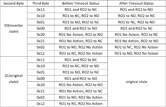
Fourth/Fifth/Sixth/Seventh bytes (cc): Latching time. Unit: ms
Note:
Since firmware v1.6.0, the latch time supports both 4 bytes and 2 bytes.
Before firmware v1.6.0, the latch time only supported 2 bytes.
The device will uplink a packet if the downlink code executes successfully.
Example payload:
1. 05 01 11 07 D0
Relay1 and Relay2 will be set to NC, lasting 2 seconds, then revert to their original state
2. 05 01 10 07 D0
Relay1 will change to NC, Relay2 will change to NO, lasting 2 seconds, and then both will revert to their original state.
3. 05 00 01 07 D0
Relay1 will change to NO, Relay2 will change to NC, lasting 2 seconds, then Relay1 will change to NC, and Relay2 will change to NO.
4. 05 00 00 07 D0
Relay1 and Relay2 will change to NO, lasting 2 seconds, then both will change to NC.
3.4.2.16 Counting -- Voltage threshold counting
When the voltage exceeds the threshold, counting begins. For details, see MOD4
AT Command
| Command | AT+VOLMAX=<voltage>,<logic> |
| Response | |
| Parameters | voltage : voltage threshold in mV logic: 0 : lower than 1: higher than if you leave the logic parameter blank, it is considered 0 |
| Examples | AT+VOLMAX=20000 If AVI1 voltage higher than VOLMAX (20000mV =20v), counter increase 1 AT+VOLMAX=20000,0 If AVI1 voltage lower than VOLMAX (20000mV =20v), counter increase 1 AT+VOLMAX=20000,1 If AVI1 voltage higher than VOLMAX (20000mV =20v), counter increase 1 |
Downlink Payload
| Payload | <prefix><voltage><logic> |
| Parameters | prefix : A5 (hex) voltage : voltage threshold in mV (2 bytes in hex) logic: (1 byte in hexadecimal) 0 : lower than 1: higher than if you leave the logic parameter blank, it is considered 1 (higher than) |
| Example | A5 4E 20 If AVI1 voltage higher than VOLMAX (20000mV =20v), counter increase 1 A5 4E 20 00 If AVI1 voltage lower than VOLMAX (20000mV =20v), counter increase 1 A5 4E 20 01 If AVI1 voltage higher than VOLMAX (20000mV =20v), counter increase 1 |
3.4.2.17 Counting -- Pre-configure the Count Number
This command allows users to pre-configure specific count numbers for various counting parameters such as Count1, Count2, or AVI1 Count. Use the AT command to set the desired count number for each configuration.
AT Command
| Command | AT+SETCNT=<counting_parameter>,<number> |
| Response | |
| Parameters | counting_parameter : 1: COUNT1 2: COUNT2 3: AVI1 Count number : Start number |
| Example | AT+SETCNT=1,10 Sets the COUNT1 to 10. |
Downlink Payload
| Payload | <prefix><counting_parameter><number> |
| Parameters | prefix : A8 (hex) counting_parameter : (1 byte in hexadecimal) 1: COUNT1 2: COUNT2 3: AVI1 Count number : Start number, 4 bytes in hexadecimal |
| Example | A8 01 00 00 00 0A Sets the COUNT1 to 10. |
3.4.2.18 Counting -- Clear Counting
This command clears the counting in counting mode.
AT Command
| Command | AT+CLRCOUNT |
| Response | - |
Downlink Payload
| Payload | <prefix><clear?> |
| Parameters | prefix : A6 (hex) clear? : 01 (hex) |
| Example | A6 01 |
3.4.2.19 Set the save intervals of the counting results, RO (Relay Output), and DO (Digital Output) states
This command configures the device to periodically save the counting results, RO (Relay Output), and DO (Digital Output) states to internal flash memory at a user-defined interval. By setting a save interval, the device ensures that critical data (counting values and output states) is preserved in case of power loss.
The save interval can be adjusted to the user's needs, with a minimum value of 30 seconds.
The saved RO/DO states can be restored after a device reset by combining this function with the AT+RODORESET command.
AT Command
| Command | AT+COUTIME=<time> |
| Response | |
| Parameters | time : seconds (0 to 16777215) |
| Example | AT+COUTIME=60 Sets the device to save its counting results, RO and DO states to the memory every 60 seconds. |
Downlink Payload
| Payload | <prefix><time> |
| Parameters | prefix : A7 time : seconds, 3 bytes in hexadecimal |
| Example | A7 00 00 3C SSets the device to save its counting results, RO and DO states to the memory every 60 seconds. |
3.4.2.20 Reset saved RO and DO states
This command allows you to reset the saved relay output (RO) and digital output (DO) states when the device joins the network. By configuring this setting, you can control whether the device should retain or reset the relay states after a reset and rejoin to the network.
AT Command
| Command | AT+RODORESET=<state> |
| Response | |
| Parameters | state : 0 : RODO will close when the device joins the network. (default) 1: After the device is reset, the previously saved RODO state (limited to MOD2 to MOD5) is read, and it will not change when the device reconnects to the network. |
| Example | AT+RODORESET=1 RODO will close when the device joins the network. (default) AT+RODORESET=0 After the device is reset, the previously saved RODO state (limited to MOD2 to MOD5) is read, and it will not change when the device reconnects to the network. |
Downlink Payload
| Payload | <prefix><state> |
| Parameters | prefix : AD state : 0 : RODO will close when the device joins the network. (default), represents as 1 byte in hexadecimal. 1: After the device is reset, the previously saved RODO state (limited to MOD2 to MOD5) is read, and it will not change when the device reconnects to the network. - represents as 1 byte in hexadecimal |
| Example | AD 01 RODO will close when the device joins the network. (default) AD 00 After the device is reset, the previously saved RODO state (limited to MOD2 to MOD5) is read, and it will not change when the device reconnects to the network. |
3.4.2.21 Encrypted payload
This command allows you to configure whether the device should upload data in an encrypted format or in plaintext. By default, the device encrypts the payload before uploading. You can toggle this setting to either upload encrypted data or transmit it without encryption.
AT Command:
| Command | AT+DECRYPT=<state> |
| Response | |
| Parameters | state : 1 : The payload is uploaded without encryption 0 : The payload is encrypted when uploaded (default) |
| Example | AT+DECRYPT=1 The payload is uploaded without encryption AT+DECRYPT=0 The payload is encrypted when uploaded (default) |
There is no downlink payload for this configuration.
3.4.2.22 Get sensor value
This command allows you to retrieve and optionally uplink sensor readings through the serial port.
AT Command
| Command | AT+GETSENSORVALUE=<state> |
| Response | |
| Parameters | state : 0 : Retrieves the current sensor reading via the serial port. 1 : Retrieves and uploads the current sensor reading via the serial port. |
| Example | AT+GETSENSORVALUE=0 Retrieves the current sensor reading via the serial port. AT+GETSENSORVALUE=1 Retrieves and uplinks the current sensor reading via the serial port. |
There is no downlink payload for this configuration.
3.4.2.23 Resetting the downlink packet count
This command manages how the node handles mismatched downlink packet counts. It offers two modes: one disables the reception of further downlink packets if discrepancies occur, while the other resets the downlink packet count to align with the server, ensuring continued communication.
AT Command
| Command | AT+DISFCNTCHECK=<state> |
| Response |
|
| Parameters | state : 0 : When the downlink packet count sent by the server is less than the node's downlink packet count or exceeds 16,384, the node stops receiving further downlink packets (default). 1 : When the downlink packet count sent by the server is less than the node's downlink packet count or exceeds 16,384, the node resets its downlink packet count to match the server's, ensuring consistency. |
| Example | AT+DISFCNTCHECK=0 When the downlink packet count sent by the server is less than the node's downlink packet count or exceeds 16,384, the node stops receiving further downlink packets (default). AT+DISFCNTCHECK=1 When the downlink packet count sent by the server is less than the node's downlink packet count or exceeds 16,384, the node resets its downlink packet count to match the server's, ensuring consistency. |
There is no downlink payload for this configuration.
3.4.2.24 When the limit bytes are exceeded, upload in batches
This command controls the behavior of the node when the combined size of the MAC commands (MACANS) from the server and the payload exceed the allowed byte limit for the current data rate (DR). The command provides two modes: one enables splitting the data into batches to ensure compliance with the byte limit, while the other prioritizes the payload and ignores the MACANS in cases of overflow.
AT Command
| Command | AT+DISMACANS=<state> |
| Response | |
| Parameters | state : 0 : When the combined size of the MACANS from the server and the payload exceeds the byte limit (11 bytes for DR0 of US915, DR2 of AS923, DR2 of AU915), the node sends a packet with a payload of 00 and a port of 4. (default) 1 : When the combined size of the MACANS from the server and the payload exceeds the byte limit for the current DR, the node ignores the MACANS and only uploads the payload. |
| Example | AT+DISMACANS=0 When the combined size of the MACANS from the server and the payload exceeds the byte limit (11 bytes for DR0 of US915, DR2 of AS923, DR2 of AU915), the node sends a packet with a payload of 00 and a port of 4. (default) AT+DISMACANS=1 When the combined size of the MACANS from the server and the payload exceeds the byte limit for the current DR, the node ignores the MACANS and only uploads the payload. |
Downlink Payload
| Payload | <prefix><state> |
| Parameters | prefix : 21 state : (2 bytes in hexadecimal) 0 : When the combined size of the MACANS from the server and the payload exceeds the byte limit (11 bytes for DR0 of US915, DR2 of AS923, DR2 of AU915), the node sends a packet with a payload of 00 and a port of 4. (default) 1 : When the combined size of the MACANS from the server and the payload exceeds the byte limit for the current DR, the node ignores the MACANS and only uploads the payload. |
| Example | 21 00 01 Set DISMACANS=1 |
3.4.2.25 Copy downlink to uplink
This command enables the device to immediately uplink the payload of a received downlink packet back to the server. The command allows for quick data replication from downlink to uplink, with a fixed port number of 100.
AT Command:
AT+RPL=5 // After receiving a downlink payload from the server, the device will immediately uplink the payload back to the server using port number 100.
Example:aa xx xx xx xx // aa indicates whether the configuration has changed: 00 means YES, and 01 means NO. xx xx xx xx are the bytes uplinked back.
For example, sending 11 22 33 44 55 66 77 will return invalid configuration 00 11 22 33 44 55 66 77.
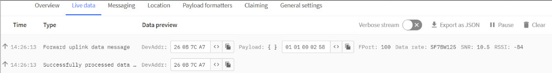
For example, if 01 00 02 58 is issued, a valid configuration of 01 01 00 02 58 will be returned.
Downlink Payload:
There is no downlink option available for this feature.
3.4.2.26 Query firmware version, frequency band, subband, and TDC time
This command is used to query key information about the device, including its firmware version, frequency band, subband, and TDC time. By sending the specified payload as a downlink, the server can retrieve this essential data from the device.
Downlink Payload:
26 01 // The downlink payload 26 01 is used to query the device's firmware version, frequency band, subband, and TDC time.
Example:

3.5 Integrating with ThingsEye.io
The Things Stack application supports integration with ThingsEye.io. Once integrated, ThingsEye.io acts as an MQTT client for The Things Stack MQTT broker, allowing it to subscribe to upstream traffic and publish downlink traffic.
3.5.1 Configuring The Things Stack
We use The Things Stack Sandbox in this example:
- In The Things Stack Sandbox, go to the Application for the LT-22222-L you added.
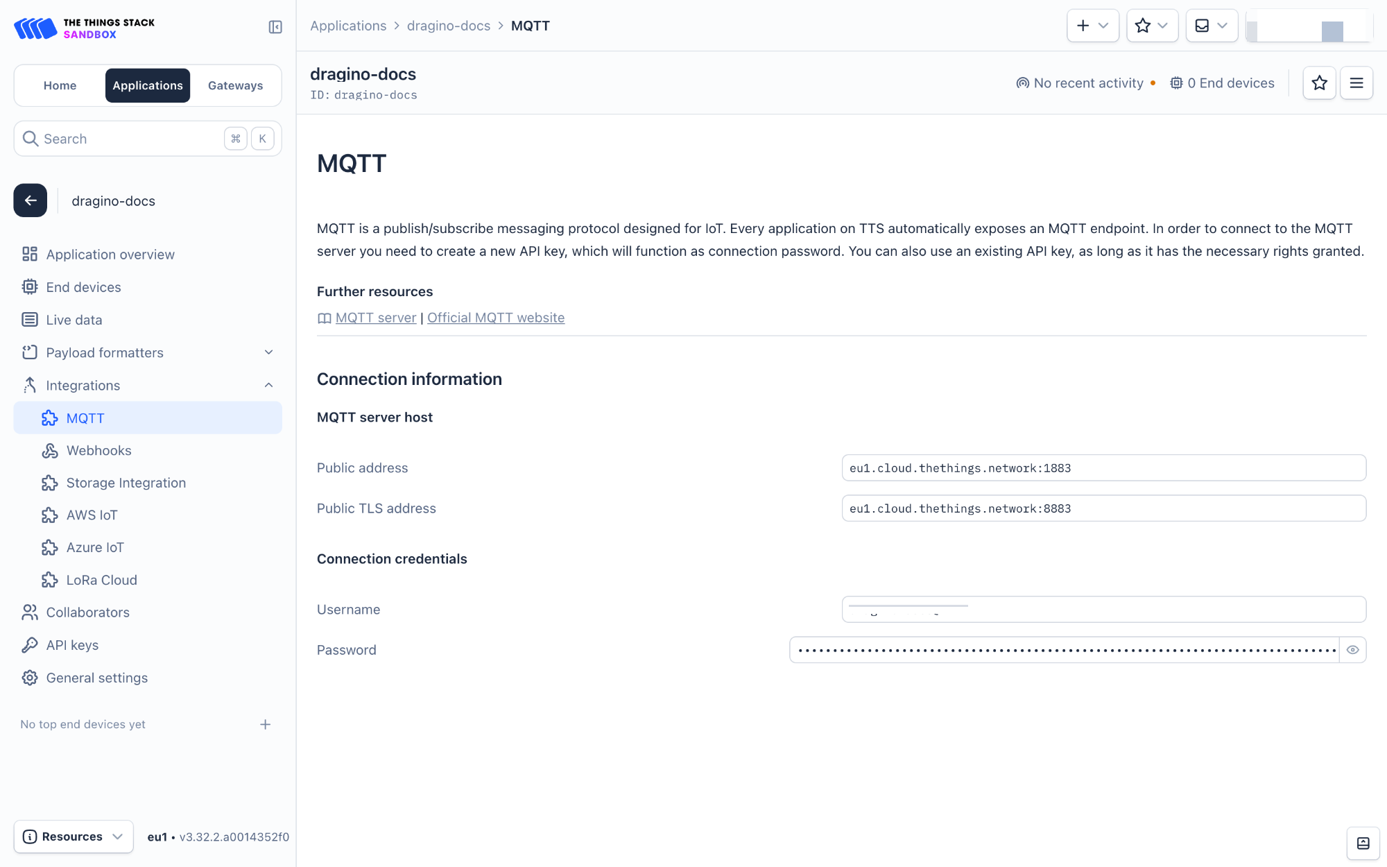
- Select MQTT under Integrations in the left menu.
- In the Connection information section, under Connection credentials, The Things Stack displays an auto-generated username. You can use it or provide a new one.
- Click the Generate new API key button to generate a password. You can view it by clicking on the visibility toggle/eye icon. The API key works as the password.
3.5.2 Configuring ThingsEye.io
The ThingsEye.io IoT platform is not open for self-registration at the moment. If you are interested in testing the platform, please send your project information to admin@thingseye.io, and we will create an account for you.
- Login to your ThingsEye.io account.
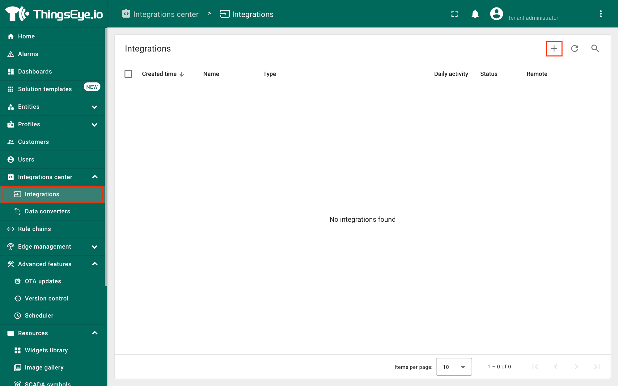
- Under the Integrations center, click Integrations.
- Click the Add integration button (the button with the + symbol).
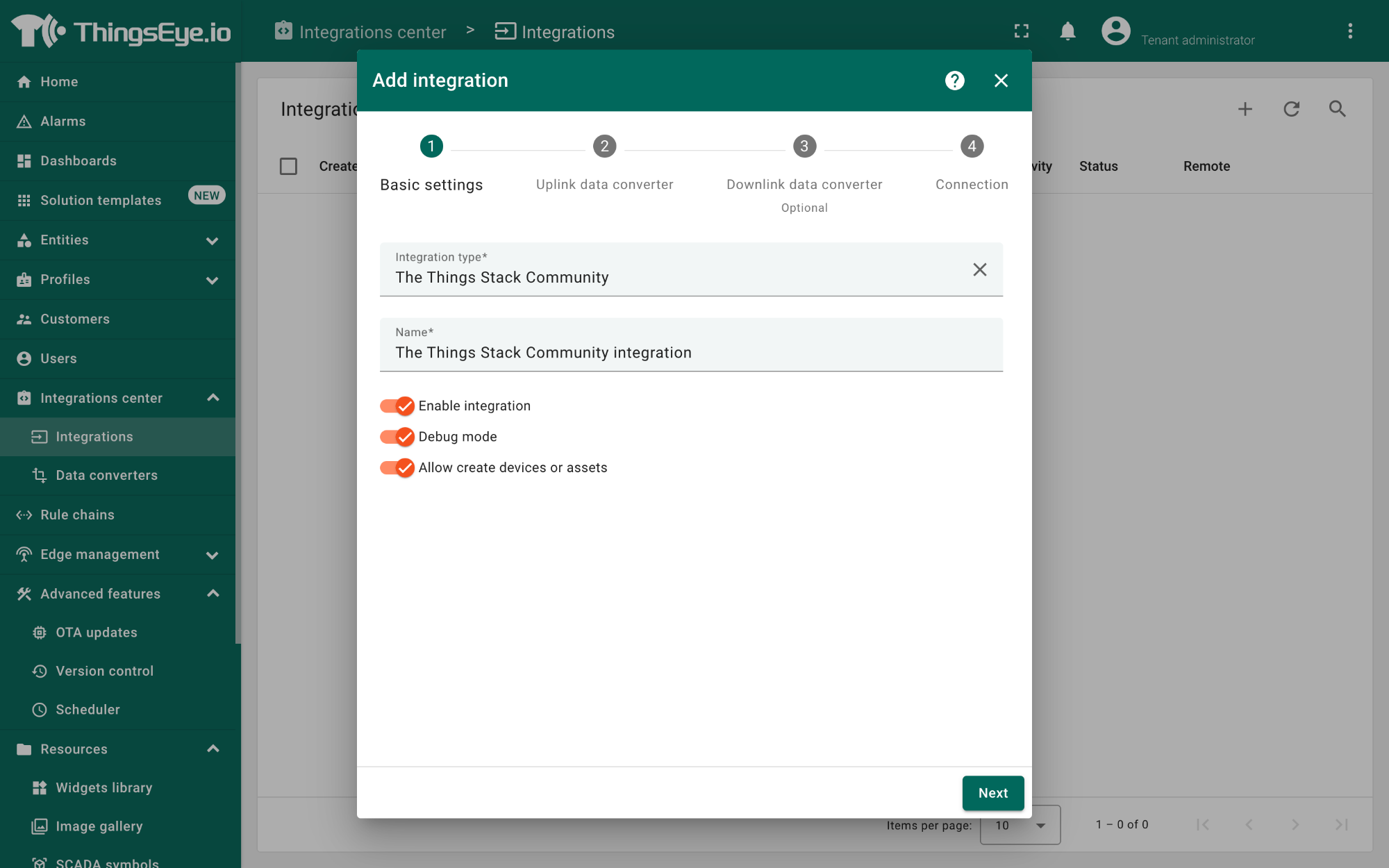
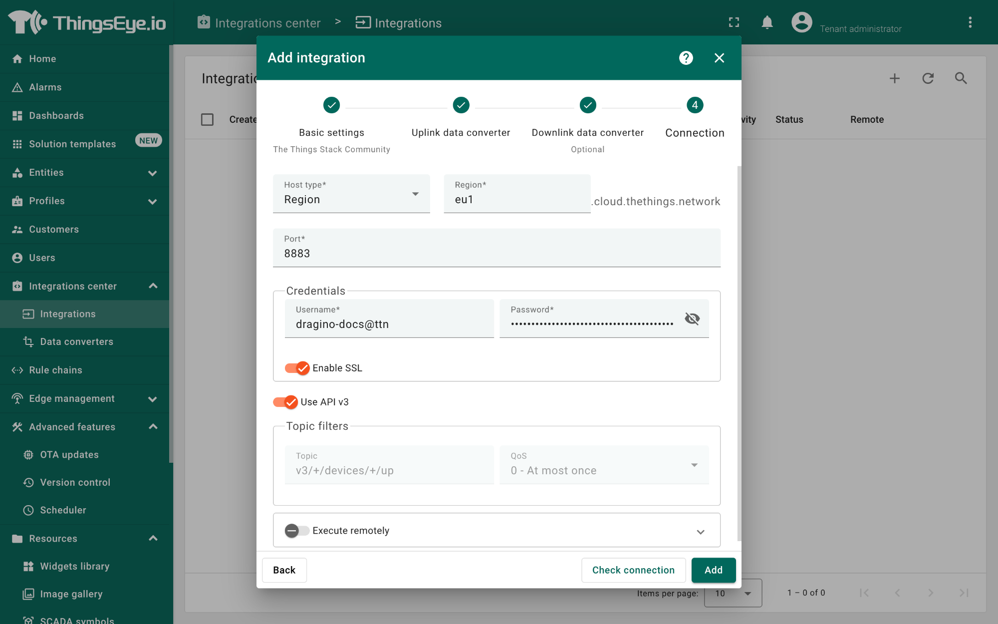
On the Add integration window, configure the following:
Basic settings:
- Select The Things Stack Community from the Integration type list.
- Enter a suitable name for your integration in the Name text box or keep the default name.
- Ensure the following options are turned on.
- Enable integration
- Debug mode
- Allow creating devices or assets
- Click the Next button. you will be navigated to the Uplink data converter tab.
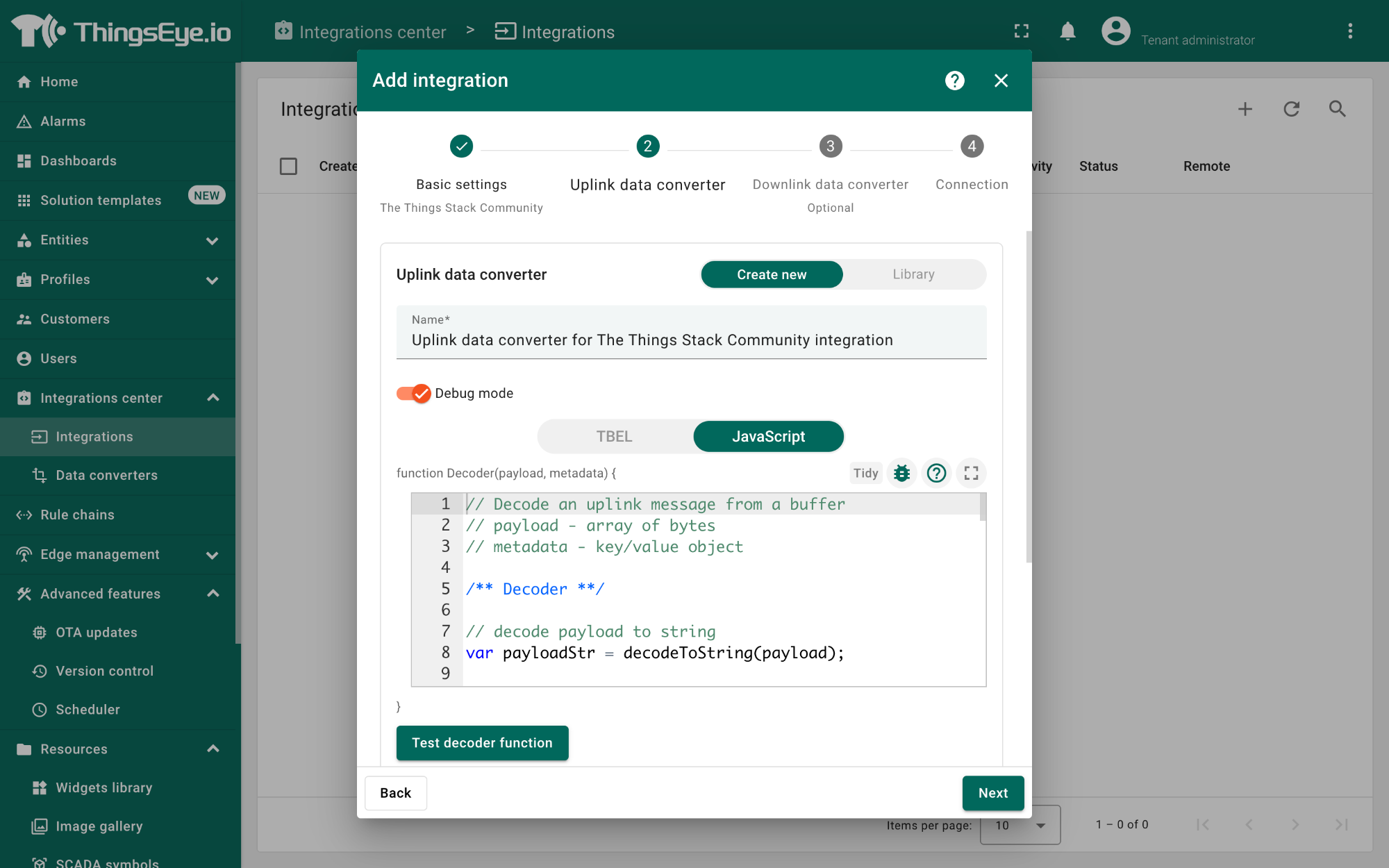
Uplink data converter:
- Click the Create new button if it is not selected by default.
- Enter a suitable name for the uplink data converter in the Name text box or keep the default name.
- Click the JavaScript button.
- Paste the uplink decoder function into the text area (first, delete the default code). The demo uplink decoder function can be found here.
- Click the Next button. You will be navigated to the Downlink data converter tab.
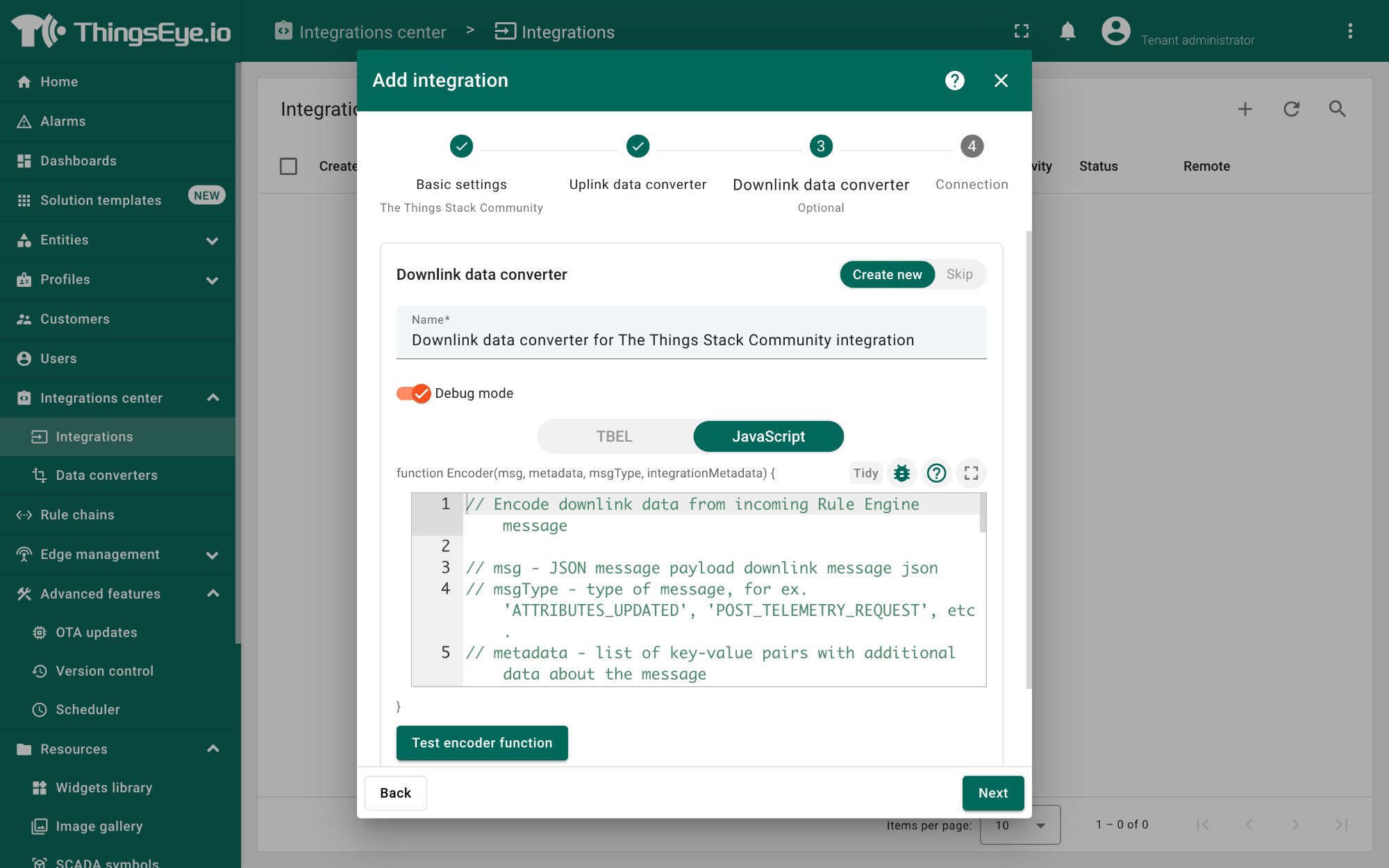
Downlink data converter (this is an optional step):
- Click the Create new button if it is not selected by default.
- Enter a suitable name for the downlink data converter in the Name text box or keep the default name.
- Click the JavaScript button.
- Paste the downlink decoder function into the text area (first, delete the default code). The demo downlink decoder function can be found here.
- Click the Next button. You will be navigated to the Connection tab.
Connection:
- Choose Region from the Host type.
- Enter the cluster of your The Things Stack in the Region textbox. You can find the cluster in the url (e.g., https://eu1.cloud.thethings.network/...).
- Enter the Username and Password of the MQTT integration in the Credentials section. The username and password can be found on the MQTT integration page of your The Things Stack account (see 3.5.1 Configuring The Things Stack).
- Click the Check connection button to test the connection. If the connection is successful, you will see the message saying Connected.
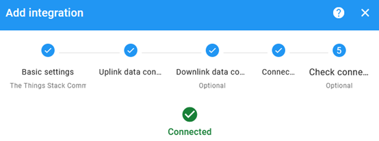
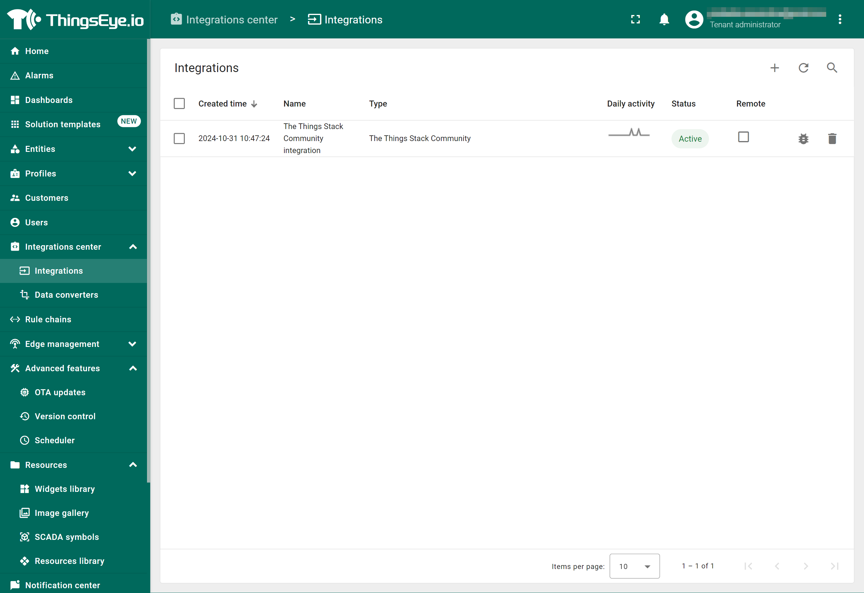
- Click the Add button.
Your integration has been added to the Integrations list and will be displayed on the Integrations page. Check whether the status is shown as Active. If not, review your configuration settings and correct any errors.
3.5.2.1 Viewing integration details
Click on your integration from the list. The Integration details window will appear with the Details tab selected. The Details tab shows all the settings you have provided for this integration.
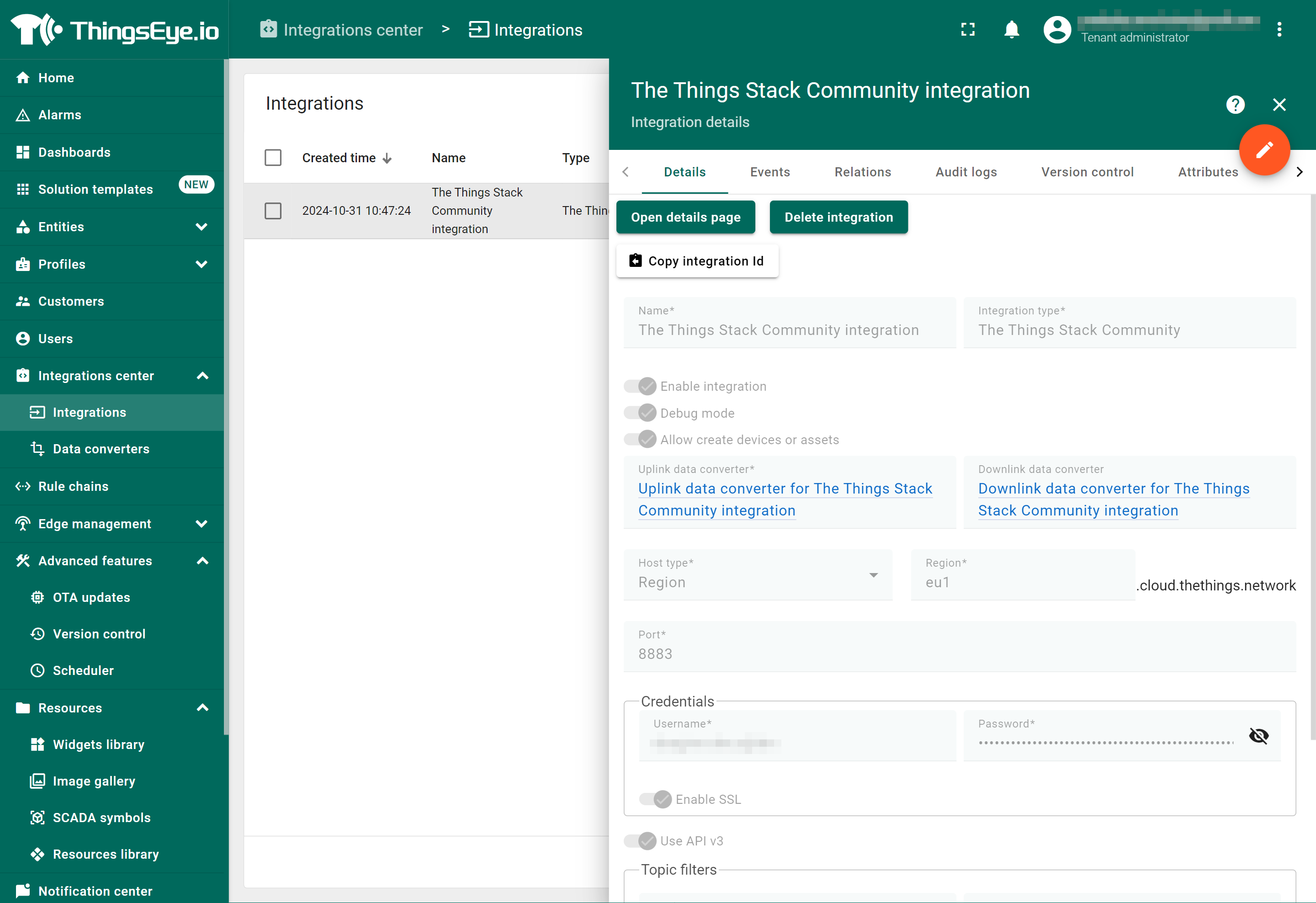
If you want to edit the settings you have provided, click on the Toggle edit mode button. Once you have done click on the Apply changes button.
3.5.2.2 Viewing events
The Events tab displays all the uplink messages from the LT-22222-L.
- Select Debug from the Event type dropdown.
- Select the time frame from the time window.
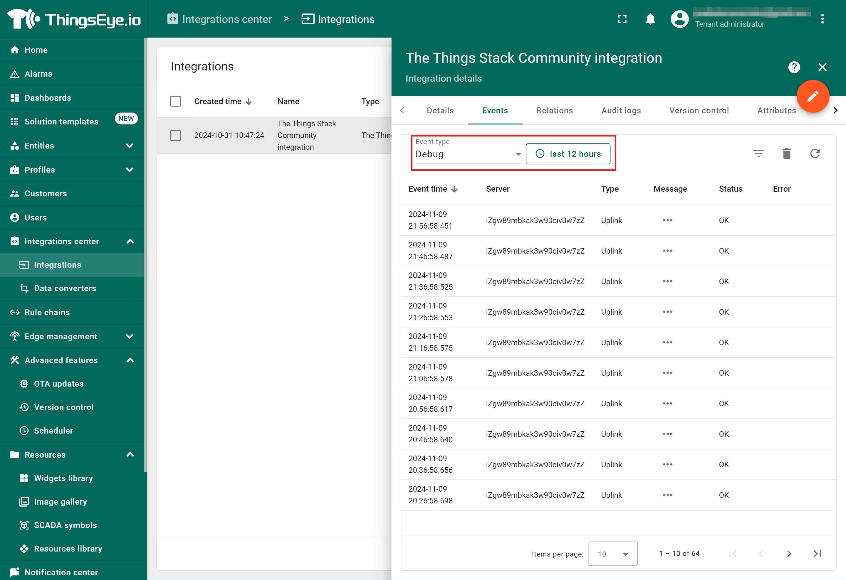
- To view the JSON payload of a message, click on the three dots (...) in the Message column of the desired message.

3.5.2.3 Deleting an integration
If you want to delete an integration, click the Delete integration button on the Integrations page.
3.5.2.4 Viewing sensor data on a dashboard
You can create a dashboard with ThingsEye to visualize the sensor data coming from the LT-22222-L. The following image shows a dashboard created for the LT-22222-L. See Creating a dashboard in ThingsEye documentation for more information.

3.6 Interface Details
3.6.1 Digital Input Ports: DI1/DI2/DI3 (For LT-33222-L, Low Active)
Supports NPN-type sensors.
3.6.2 Digital Input Ports: DI1/DI2
The DI ports of the LT-22222-L can support NPN, PNP, or dry contact output sensors.
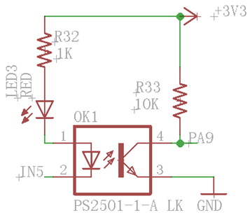
The part of the internal circuit of the LT-22222-L shown below includes the NEC2501 photocoupler. The active current from NEC2501 pin 1 to pin 2 is 1 mA, with a maximum allowable current of 50 mA. When active current flows from NEC2501 pin 1 to pin 2, the DI becomes active HIGH and the DI LED status changes.
When connecting a device to the DI port, both DI1+ and DI1- must be connected.
Example 1: Connecting to a low-active sensor.
This type of sensor outputs a low (GND) signal when active.
Connect the sensor's output to DI1-
Connect the sensor's VCC to DI1+.
When the sensor is active, the current between NEC2501 pin 1 and pin 2 will be:
![]() = DI1+ / 1K.
= DI1+ / 1K.
For example, if DI1+ = 12V, the resulting current is ![]() = 12mA. Therefore, the LT-22222-L will be able to detect this active signal.
= 12mA. Therefore, the LT-22222-L will be able to detect this active signal.
Example 2: Connecting to a high-active sensor.
This type of sensor outputs a high signal (e.g., 24V) when active.
Connect the sensor's output to DI1+
Connect the sensor's GND DI1-.
When the sensor is active, the current between NEC2501 pin1 and pin2 will be:
![]() = DI1+ / 1K.
= DI1+ / 1K.
If DI1+ = 24V, the resulting current![]() is 24mA, Therefore, the LT-22222-L will detect this high-active signal.
is 24mA, Therefore, the LT-22222-L will detect this high-active signal.
Example 3: Connecting to a 220V high-active sensor.
Assume that you want to monitor an active signal higher than 220V without damaging the photocoupler
Connect the sensor's output to DI1+ with a 50K resistor in series.
Connect the sensor's GND DI1-.
When the sensor is active, the current between NEC2501 pin1 and pin2 will be:
![]() = DI1+ / 51K.
= DI1+ / 51K.
If the sensor output is 220V, then ![]() = DI1+ / 51K = 4.3mA. Therefore, the LT-22222-L will be able to safely detect this high-active signal.
= DI1+ / 51K = 4.3mA. Therefore, the LT-22222-L will be able to safely detect this high-active signal.

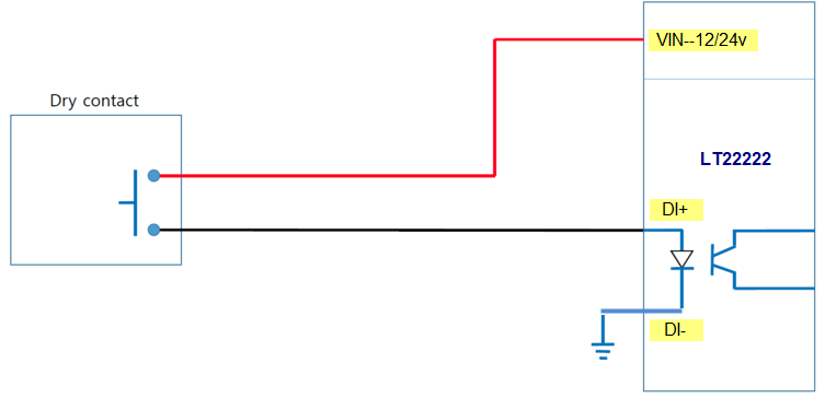
Example 4: Connecting to a Dry Contact sensor
From the DI port circuit above, activating the photocoupler requires a voltage difference between the DI+ and DI- ports. However, the Dry Contact sensor is a passive component and cannot provide this voltage difference on its own.
To detect a Dry Contact, you can supply a power source to one of the pins of the Dry Contact. A reference circuit diagram is shown below.
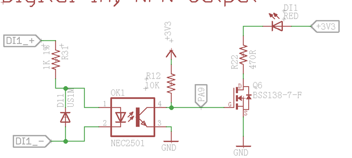
Example 5: Connecting to an Open Collector
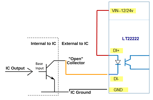
3.6.3 Digital Output Ports: DO1/DO2
NPN output: GND or Float. The maximum voltage that can be applied to the output pin is 36V.
Note: The DO pins will float when the device is powered off.
3.6.4 Analog Input Interfaces
The analog input interface is shown below. The LT-22222-L will measure the IN2 voltage to calculate the current passing through the load. The formula is:
AC2 = (IN2 voltage )/12
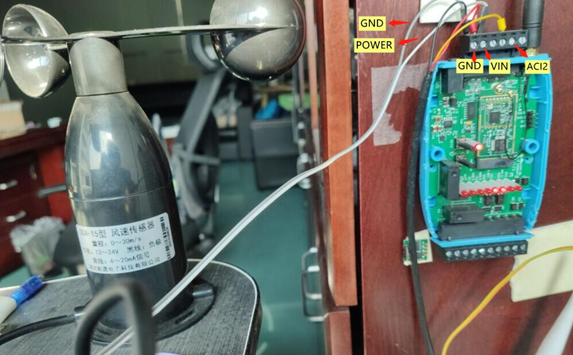
Example: Connecting a 4~20mA sensor
We will use the wind speed sensor as an example for reference only.
Specifications of the wind speed sensor:
Red: 12~24V
Yellow: 4~20mA
Black: GND
Connection diagram:
Example: Connecting to a regulated power supply to measure voltage

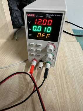

Specifications of the regulated power supply:
Red: 12~24v
Black: GND
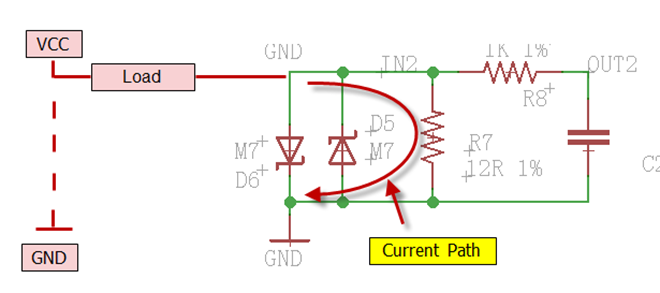
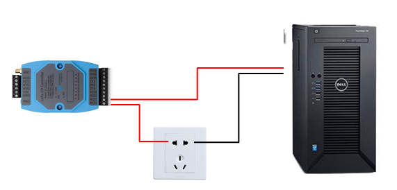
3.6.5 Relay Output
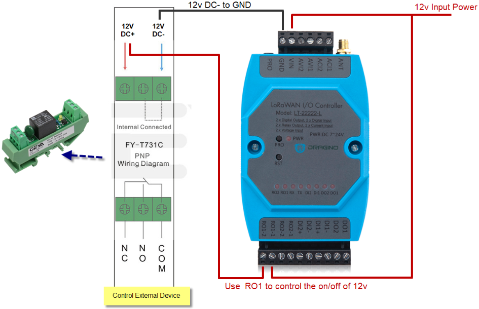
The LT-22222-L has two relay interfaces, RO1 and RO2, each using two pins of the screw terminal (ROx-1 and ROx-2 where x is the port number, 1 or 2). You can connect a device's power line in series with one of the relay interfaces (e.g., RO1-1 and RO1-2 screw terminals). See the example below:
Note: The ROx pins will be in the Open (NO) state when the LT-22222-L is powered off.
3.7 LED Indicators
The table below lists the behaviour of LED indicators for each port function.
| LEDs | Feature |
| PWR | Always on when there is power |
| TX | Device booting: TX blinks 5 times. Successful network joins: TX remains ON for 5 seconds. Transmit a LoRa packet: TX blinks once |
| RX | RX blinks once when a packet is received. |
| DO1 | For LT-22222-L: ON when DO1 is low, OFF when DO1 is high |
| DO2 | For LT-22222-L: ON when DO2 is low, OFF when DO2 is high |
| DI1 | For LT-22222-L: ON when DI1 is high, OFF when DI1 is low |
| DI2 | For LT-22222-L: ON when DI2 is high, OFF when DI2 is low |
| RO1 | For LT-22222-L: ON when RO1 is closed, OFF when RO1 is open |
| RO2 | For LT-22222-L: ON when RO2 is closed, OFF when RO2 is open |
4. Using AT Commands
The LT-22222-L supports programming using AT Commands.
4.1 Connecting the LT-22222-L to a PC
You can use a USB-to-TTL adapter/converter along with a 3.5mm Program Cable to connect the LT-22222-L to a PC, as shown below.

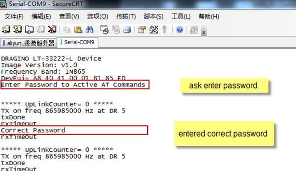
On the PC, you need to set the serial tool (such as PuTTY or SecureCRT) to a baud rate of 9600 to access the serial console of LT-22222-L. Access to AT commands is disabled by default, and a password (default: 123456) must be entered to enable AT command access, as shown below:
4.2 LT-22222-L related AT commands
The following is the list of all the AT commands related to the LT-22222-L, except for those used for switching between working modes.
- AT+<CMD>? : Help on <CMD>
- AT+<CMD> : Run <CMD>
- AT+<CMD>=<value> : Set the value
- AT+<CMD>=? : Get the value
- ATZ: Trigger a reset of the MCU
- AT+FDR: Reset Parameters to factory default, reserve keys
- AT+DEUI: Get or set the Device EUI (DevEUI)
- AT+DADDR: Get or set the Device Address (DevAddr)
- AT+APPKEY: Get or set the Application Key (AppKey)
- AT+NWKSKEY: Get or set the Network Session Key (NwkSKey)
- AT+APPSKEY: Get or set the Application Session Key (AppSKey)
- AT+APPEUI: Get or set the Application EUI (AppEUI)
- AT+ADR: Get or set the Adaptive Data Rate setting. (0: OFF, 1: ON)
- AT+TXP: Get or set the Transmit Power (0-5, MAX:0, MIN:5, according to LoRaWAN Specification)
- AT+DR: Get or set the Data Rate. (0-7 corresponding to DR_X)
- AT+DCS: Get or set the ETSI Duty Cycle setting - 0=disable, 1=enable - Only for testing
- AT+PNM: Get or set the public network mode. (0: off, 1: on)
- AT+RX2FQ: Get or set the Rx2 window frequency
- AT+RX2DR: Get or set the Rx2 window data rate (0-7 corresponding to DR_X)
- AT+RX1DL: Get or set the delay between the end of the Tx and the Rx Window 1 in ms
- AT+RX2DL: Get or set the delay between the end of the Tx and the Rx Window 2 in ms
- AT+JN1DL: Get or set the Join Accept Delay between the end of the Tx and the Join Rx Window 1 in ms
- AT+JN2DL: Get or set the Join Accept Delay between the end of the Tx and the Join Rx Window 2 in ms
- AT+NJM: Get or set the Network Join Mode. (0: ABP, 1: OTAA)
- AT+NWKID: Get or set the Network ID
- AT+FCU: Get or set the Frame Counter Uplink (FCntUp)
- AT+FCD: Get or set the Frame Counter Downlink (FCntDown)
- AT+CLASS: Get or set the Device Class
- AT+JOIN: Join Network
- AT+NJS: Get OTAA Join Status
- AT+SENDB: Send hexadecimal data along with the application port
- AT+SEND: Send text data along with the application port
- AT+RECVB: Print the last received data in binary format (with hexadecimal values)
- AT+RECV: Print the last received data in raw format
- AT+VER: Get the current image version and Frequency Band
- AT+CFM: Get or Set the confirmation mode (0-1)
- AT+CFS: Get confirmation status of the last AT+SEND (0-1)
- AT+SNR: Get the SNR of the last received packet
- AT+RSSI: Get the RSSI of the last received packet
- AT+TDC: Get or set the application data transmission interval in ms
- AT+PORT: Get or set the application port
- AT+DISAT: Disable AT commands
- AT+PWORD: Set password, max 9 digits
- AT+CHS: Get or set the Frequency (Unit: Hz) for Single Channel Mode
- AT+CHE: Get or set eight channels mode, Only for US915, AU915, CN470
- AT+CFG: Print all settings
4.2 Common AT Command Sequence
4.2.1 Multi-channel ABP mode (Use with SX1301/LG308)
If the device has not yet joined the network:
123456 //Enter the password to enable AT command access
AT+FDR //Reset parameters to factory default, Reserve keys
123456 //Enter the password to enable AT command access
AT+NJM=0 //Set to ABP mode
ATZ //Reset MCU
If the device has already joined the network:
AT+NJM=0
ATZ
4.2.2 Single-channel ABP mode (Use with LG01/LG02)
123456 // Enter the password to enable AT commands access
AT+FDR // Reset parameters to Factory Default, Reserve keys
123456 // Enter the password to enable AT command access
AT+CLASS=C // Set to CLASS C mode
AT+NJM=0 // Set to ABP mode
AT+ADR=0 // Set the Adaptive Data Rate Off
AT+DR=5 // Set Data Rate
AT+TDC=60000 // Set transmit interval to 60 seconds
AT+CHS=868400000 // Set transmit frequency to 868.4 MHz
AT+RX2FQ=868400000 // Set RX2 frequency to 868.4 MHz (according to the result from the server)
AT+RX2DR=5 // Set RX2 DR to match the downlink DR from the server. See below.
AT+DADDR=26 01 1A F1 // Set Device Address. The Device Address can be found in the application on the LoRaWAN NS.
ATZ // Reset MCU
Note:
1. Ensure that the device is set to ABP mode in the LoRaWAN Network Server.
2. Verify that the LG01/02 gateway RX frequency matches the AT+CHS setting exactly.
3. Make sure the SF/bandwidth settings in the LG01/LG02 match the settings of AT+DR. Refer to this link to see what DR means.
4. The commands AT+RX2FQ and AT+RX2DR enable downlink functionality. To set the correct parameters, you can check the actual downlink parameters to be used as shown below. Here, RX2FQ should be set to 868400000 and RX2DR should be set to 5.
4.2.3 Change to Class A
If the sensor has JOINED:
AT+CLASS=A
ATZ
5. Case Study
5.1 Counting how many objects pass through the flow line
See How to set up to setup counting for objects passing through the flow line.
6. FAQ
This section contains some frequently asked questions, which can help you resolve common issues and find solutions quickly.
6.1 How to update the firmware?
Dragino frequently releases firmware updates for the LT-22222-L. Updating your LT-22222-L with the latest firmware version helps to:
- Support new features
- Fix bugs
- Change LoRaWAN frequency bands
You will need the following things before proceeding:
- 3.5mm programming cable (included with the LT-22222-L as an additional accessory)
- USB to TTL adapter/converter
- Download and install the STM32 Flash loader. (replaced by STM32CubeProgrammer)
- Download the latest firmware image from LT-22222-L firmware image files. Check the file name of the firmware to find the correct region.
Below is the hardware setup for uploading a firmware image to the LT-22222-L:
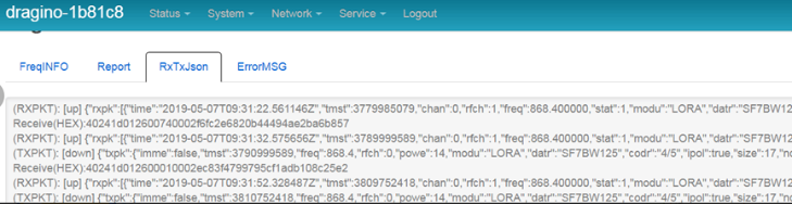
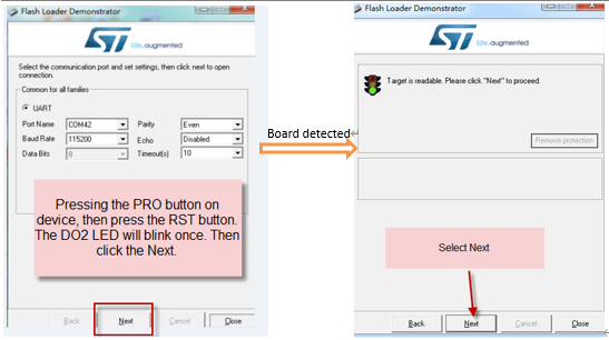
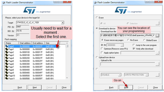
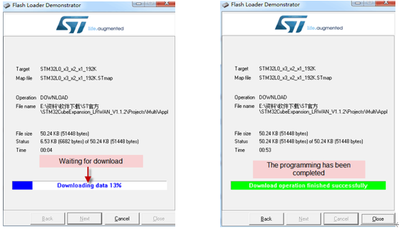
Start the STM32 Flash Loader and choose the correct COM port to update.
For LT-22222-L:
Hold down the PRO button, then briefly press the RST button. The DO1 LED will change from OFF to ON. When the DO1 LED is ON, it indicates that the device is in firmware download mode.
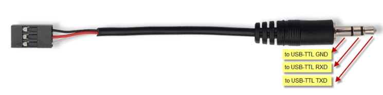
Note: If you have lost the programming cable, you can make one from a 3.5 mm cable. The pin mapping is as follows:
6.2 How to change the LoRaWAN frequency band/region?
You can follow the introductions on how to upgrade the image. When downloading, select the required image file.
6.3 How to set up LT-22222-L to work with a Single Channel Gateway, such as LG01/LG02?
In this case, you need to set the LT-22222-L to work in ABP mode and transmit on only one frequency.
We assume you have an LG01/LG02 working on the frequency 868400000. Below are the steps.
Step 1: Log in to The Things Stack Sandbox account and create an ABP device in the application. To do this, use the manual registration option as explained in section 3.2.2.2, Adding a Device Manually. Select Activation by Personalization (ABP) under Activation Mode. Enter the DevEUI exactly as shown on the registration information sticker, then generate the Device Address, Application Session Key (AppSKey), and Network Session Key (NwkSKey).

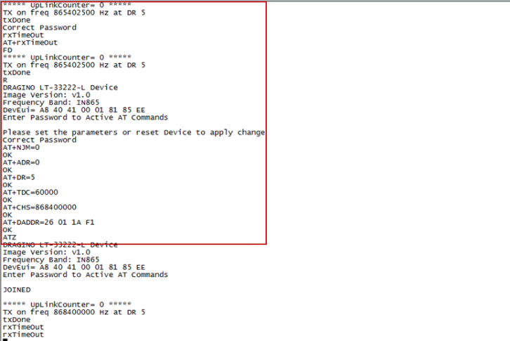
Step 2: Run AT commands to configure the LT-22222-L to operate in single-frequency and ABP mode. The AT commands are as follows:
123456 : Enter the password to enable AT access.
AT+FDR : Reset parameters to factory default, keeping keys reserved.
AT+NJM=0 : Set to ABP mode.
AT+ADR=0 : Disable the Adaptive Data Rate (ADR).
AT+DR=5 : Set Data Rate (Use AT+DR=3 for the 915 MHz band).
AT+TDC=60000 : Set transmit interval to 60 seconds.
AT+CHS=868400000 : Set transmit frequency to 868.4 MHz.
AT+DADDR=xxxx : Set the Device Address (DevAddr)
AT+APPKEY=xxxx: Get or set the Application Key (AppKey)
AT+NWKSKEY=xxxx: Get or set the Network Session Key (NwkSKey)
AT+APPSKEY=xxxx: Get or set the Application Session Key (AppSKey)
ATZ : Reset MCU.
The following figure shows the screenshot of the command set above, issued using a serial tool:
6.4 How to change the uplink interval?
Please see this link: http://wiki.dragino.com/xwiki/bin/view/Main/How%20to%20set%20the%20transmit%20time%20interval/
6.5 Can I see the counting event in the serial output?
You can run the AT command AT+DEBUG to view the counting event in the serial output. If the firmware is too old and doesn’t support AT+DEBUG, update to the latest firmware first.
6.6 Can I use point-to-point communication with LT-22222-L?
Yes, you can. Please refer to the Point-to-Point Communication of LT-22222-L page. The firmware that supports point-to-point communication can be found here.
6.7 Why does the relay output default to an open relay after the LT-22222-L is powered off?
- If the device is not properly shut down and is directly powered off.
- It will default to a power-off state.
- In modes 2 to 5, the DO/RO status and pulse count are saved to flash memory.
- After a restart, the status before the power failure will be read from Flash.
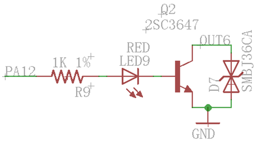
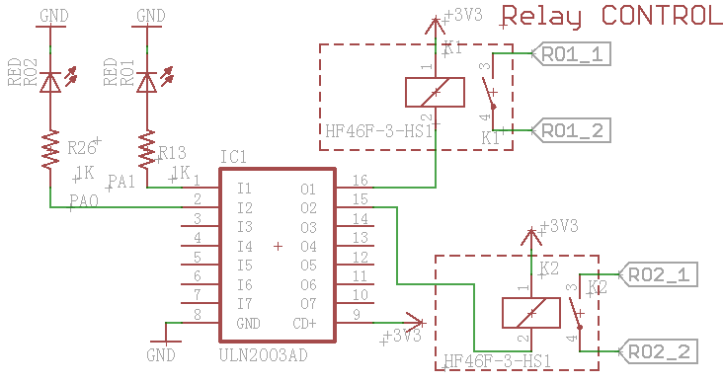
6.8 Can I set up LT-22222-L as an NC (Normally Closed) relay?
The LT-22222-L's built-in relay is Normally Open (NO). You can use an external relay to achieve a Normally Closed (NC) configuration. The circuit diagram is shown below:
6.9 Can the LT-22222-L save the RO state?
To enable this feature, the firmware version must be 1.6.0 or higher.
6.10 Why does the LT-22222-L always report 15.585V when measuring the AVI?
It is likely that the GND is not connected during the measurement, or that the wire connected to the GND is loose.
7. Troubleshooting
This section provides some known troubleshooting tips.
7.1 Downlink isn't working. How can I solve this?
Please refer to this link for debugging instructions: LoRaWAN Communication Debug
7.2 Having trouble uploading an image?
Please refer to this link for troubleshooting: Firmware Upgrade Instruction
7.3 Why can't I join TTN in the US915 /AU915 bands?
It might be related to the channel mapping. Please refer to this link for details.
7.4 Why can the LT-22222-L perform uplink normally, but cannot receive downlink?
The FCD count of the gateway is inconsistent with the FCD count of the node, causing the downlink to remain in the queue.
Use this command to synchronize their counts: Resets the downlink packet count
8. Ordering information
LT-22222-L-XXX:
XXX:
- EU433: LT with frequency bands EU433
- EU868: LT with frequency bands EU868
- KR920: LT with frequency bands KR920
- CN470: LT with frequency bands CN470
- AS923: LT with frequency bands AS923
- AU915: LT with frequency bands AU915
- US915: LT with frequency bands US915
- IN865: LT with frequency bands IN865
- CN779: LT with frequency bands CN779
9. Package information
Package Includes:
- 1 x LT-22222-L I/O Controller
- 1 x LoRa antenna matched to the frequency of the LT-22222-L
- 1 x bracket for DIN rail mounting
- 1 x 3.5 mm programming cable
Dimension and weight:
- Package Size / pcs : 145×80×50 mm
- Weight / pcs : 180 g
10. Support
Support is available Monday to Friday, from 09:00 to 18:00 GMT+8. Due to different time zones, we cannot offer live support. However, your questions will be answered as soon as possible within the aforementioned schedule.
Please provide as much information as possible regarding your inquiry (e.g., product models, a detailed description of the problem, steps to replicate it, etc.) and send an email to support@dragino.cc