Firmware Upgrade Instruction for STM32 base products
Table of Contents:
- 1. Introduction
- 2. Hardware Upgrade Method Support List
- 3. UART Upgrade Guide
- 4. ST-Link v2 Upgrade
- 4.2. Firmware upgrade using STM32 Cubeprogramer
1. Introduction
This instruction shows how to upgrade firmware for Dragino products base on STM32 solution. The upgrade can use 2 hardware connections: UART upgrade or ST Link v2 upgrade. Some models supports both methods and some only one of them.
2. Hardware Upgrade Method Support List
| Dragino STM32 base hardware Upgrade Methods | ||
|---|---|---|
| Model | UART Connection | ST-Link Connection |
| LSN50 v1, LoRa ST, | Hardware Connect Photo | Hardware Connect Photo |
| LGT92, LBT1 | × | Hardware Connect Photo |
| LT-33222-L, LT-22222 | Hardware Connect Photo | × |
| LHT65 | × | Hardware Connect Photo |
| RS485-LN | Hardware Connect Photo | × |
| LSN50v2, NBSN95,LSE01,LDDS20, LDS03A,LDDS75 | Hardware Connect Photo | Hardware Connect Photo |
| LAQ4 | × | Hardware Connect Photo |
| Hardware Connection Photo | Hardware Connect Photo | |
| LTC2 | × | Hardware Connect Photo |
3. UART Upgrade Guide
3.1 Hardware Connection
3.1.1 LSN50 v1
Connection for LSN50 v1
3.1.2 LSN50 v2/LSN50v2-D22/LSN50v2-D23/LSN50v2-S31B
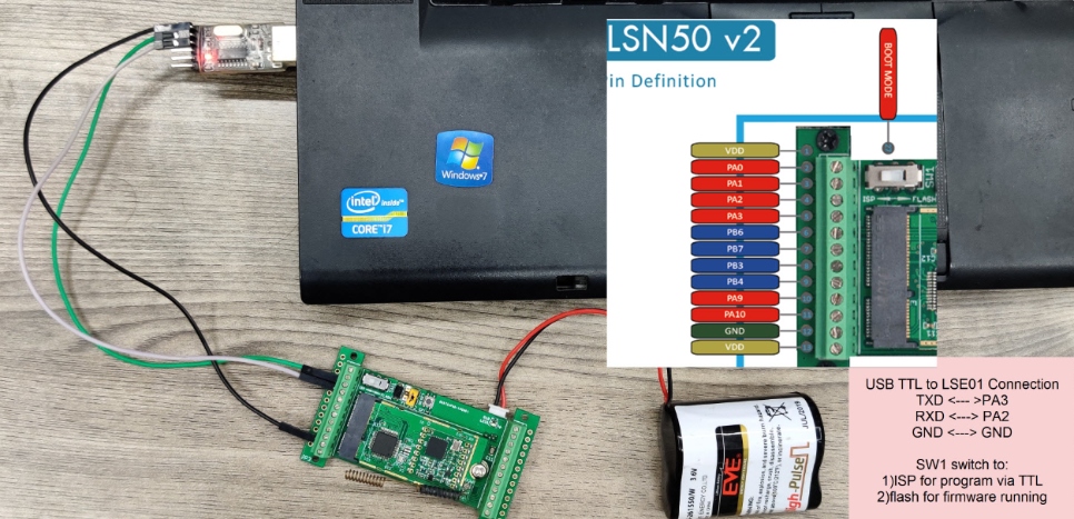 a
a
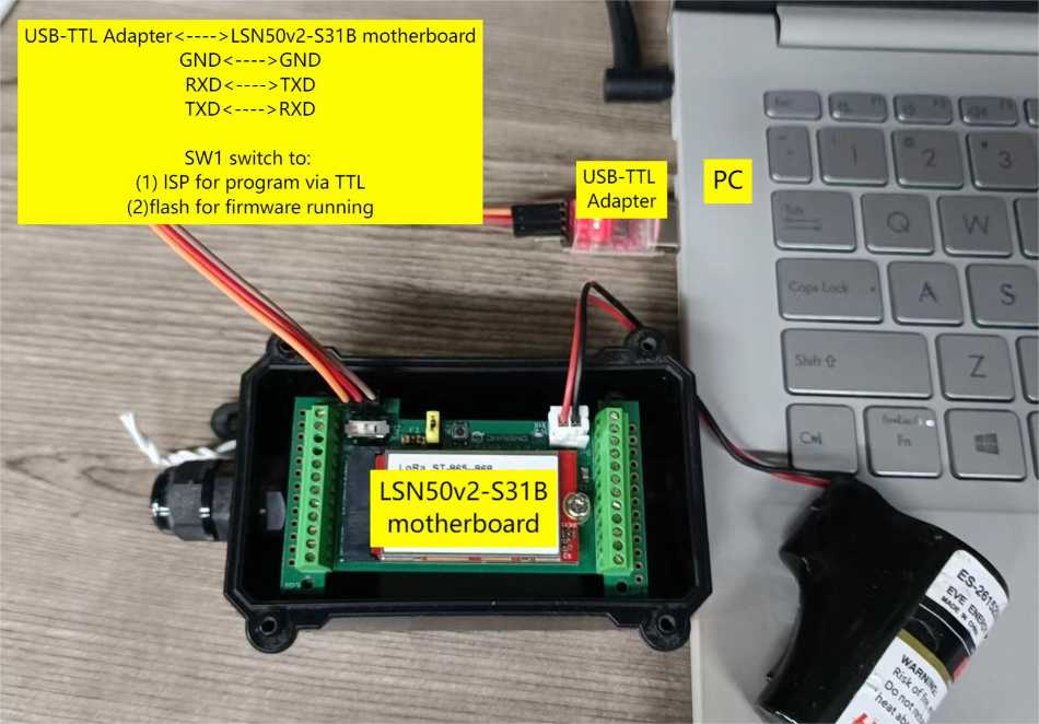
Connection for LSN50 Type V2
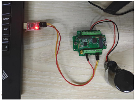
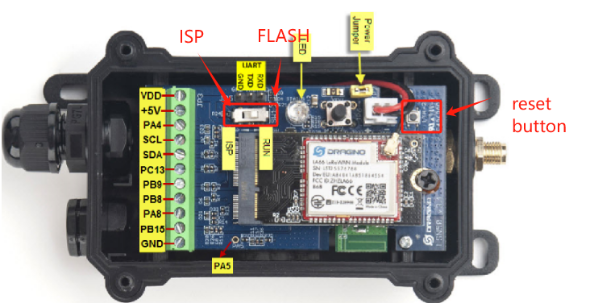
3.1.3 RS485-BL/LDDS75/LDDS20/LSE01
Connection for RS485-BL base mother board
For UART Update, need:
- Connect USB-TTL TXD <--> Device UART_RX
- Connect USB-TTL RXD <--> Device UART_TX
- Connect USB-TTL GND <--> Device GND
- Put Switch SW1 to ISP position
- Connect JP2 jumper (Yellow one), so device is power on.
3.2 Upgrade Steps
Step 1: Download Flash Loader.
Step 2: Download the Image files, which can be found in the product user manual.
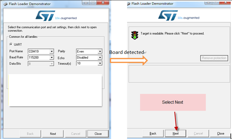
Step 3: Open Flashloader; choose the correct COM port to update, Please notice that the serial setting must follow below photos.
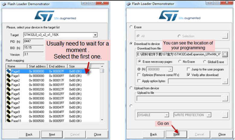
Step 4: Set The device into ISP Mode. Then Press the Reset Button, In the Flash tool, click next and the tool will detect the board type.
Note: ISP Mode can be a switch or a button, depends on the product. The device only need to be in ISP mode when press the reset button for UART Upgrade. So if the device is of a button type ISP mode, user can release the ISP button after press the reset button.
UART Upgrade
UART Upgrade
UART Upgrade
Step 5: For switch type ISP Mode, After upgrade,please remember to switch back to Flash mode and press RESET Button to run the firmware.
Step 6: Always run AT+FDR after update firmware. This is to reset the device to factory settings of the new firmware.
3.3 Trouble shooting
3.3.1 General Check List
1. Double check if follow up exactly the steps as manual.
2. Check if hardware works fine:
- check if AT command works, in both TX/RX
- check if the device are in upgrade mode, see product manual for upgrade mode indicator.
- check if reset button works
3. If you use Windows10 system. Please change the flash loader to run in Windows7 compatibility mode.
4. We see a case the FT232 USB TTL adapter has reliability issue with the PC USB chipset(Intel). In this case, even above, it still has serious reliability issue for uploading. If this happen, change a PC or change a USB to TTL adapter will solve.
3.4 Flash Loader -- Unable to Load data from this file
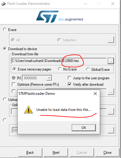
Unable to Load data from this file
The previous LSN50 firmware file is stored in github. If user use right click --> Save As to get the hex file. This error will happen. Now the LSN50 firmware file has been moved to LSN50 Firmware to avoid this happen.
3.5 Alternative method to flash via UART
Alternative method to flash STM32 via UART.pdf
4. ST-Link v2 Upgrade
4.1 Hardware Connections
4.1.1 LSN50 v2/LSN50v2-D22/LSN50v2-D23 Type
ST-Link Connections for LSn50 V2/LSN50v2-D22/LSN50v2-D23 Type
4.1.2 LGT92/LBT1 ST-Link v2 Connection
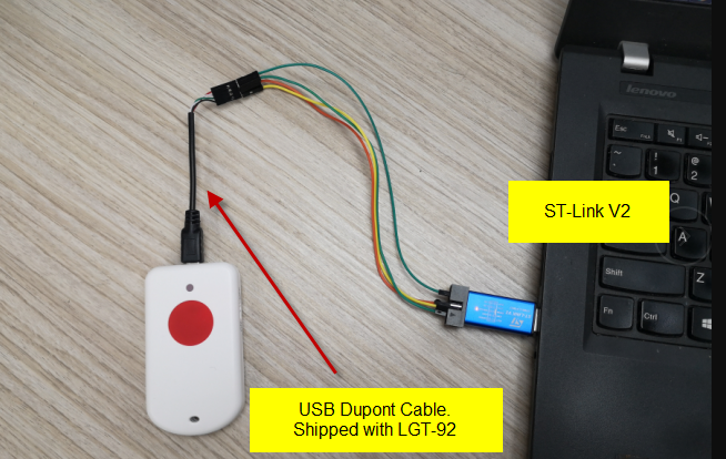
Connection to LGT92
- ST-LINK v2 5.0v <--> Dupont Cable red pin
- ST-LINK v2 GND <--> Dupont Cable black pin
- ST-LINK v2 SWCLK <--> Dupont Cable green pin
- ST-LINK v2 SWDIO <--> Dupont Cable white pin
4.1.3 LAQ4 ST-Link v2 Connection
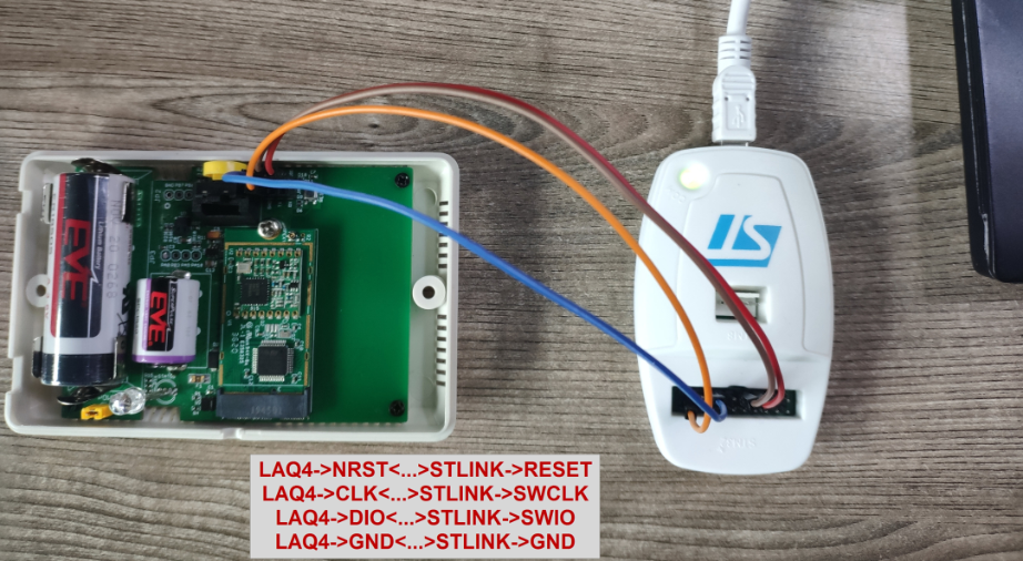
Connection to LAQ4
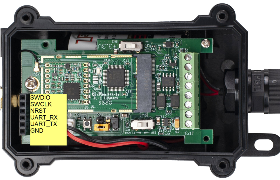
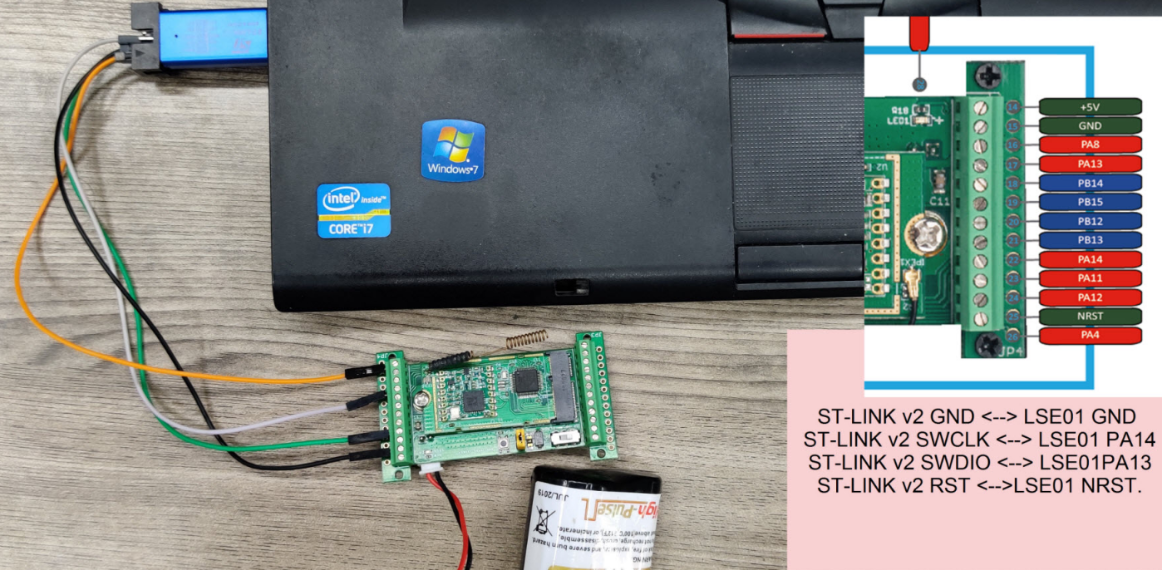
4.1.4 RS485-BL/LDDS75/LDDS20/LSE01
Connection for RS485-BL base mother board
When use ST-Link v2 to update, need:
- ST-LINK v2 RESET <--> NRST
- ST-LINK v2 GND <--> GND
- ST-LINK v2 SWCLK <--> SWCLK
- ST-LINK v2 SWDIO <--> SWDIO
- ST-LINK (VDD 3.3v,pin19) <--> ST-LINK (TVCC ,pin1) a wire to connect two pins of ST-Link together.
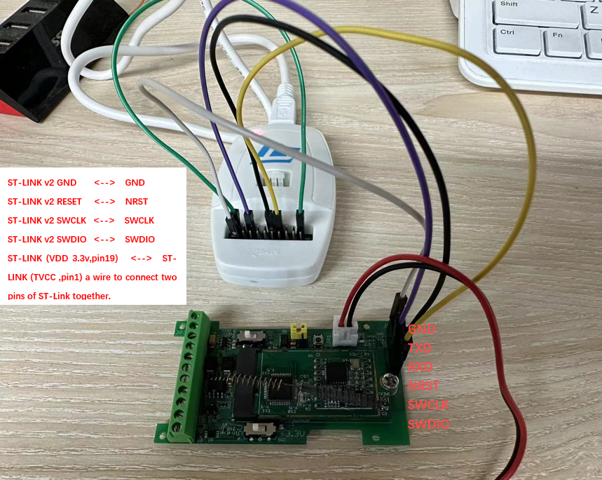
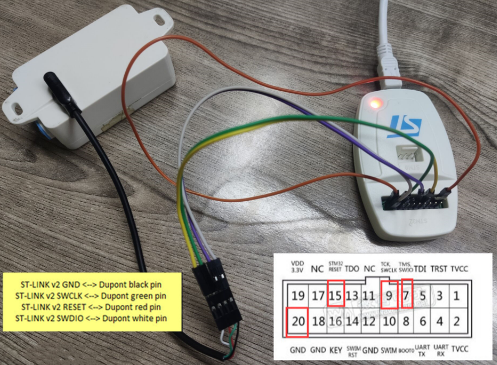
4.1.5 LTC2
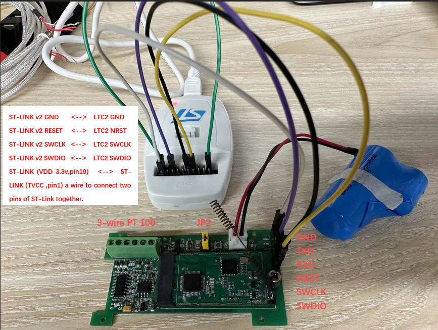
Connection for LTC2 base mother board
Connection:
- ST-LINK v2 GND <--> LTC2 GND
- ST-LINK v2 RESET <--> LTC2 NRST
- ST-LINK v2 SWCLK <--> LTC2 SWCLK
- ST-LINK v2 SWDIO <--> LTC2 SWDIO
- ST-LINK (VDD 3.3v,pin19) <--> ST-LINK (TVCC ,pin1) a wire to connect two pins of ST-Link together.
4.2. Firmware upgrade using STM32 Cubeprogramer
Step1: download STM32 Cubeprogramer
Step2: Place the button on the base plate at the ISP and press the reset button
Step3: Enter the download interface
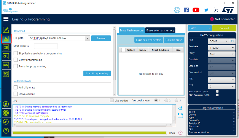
Step4: Connect serial port correctly and select UART/ST-LINK
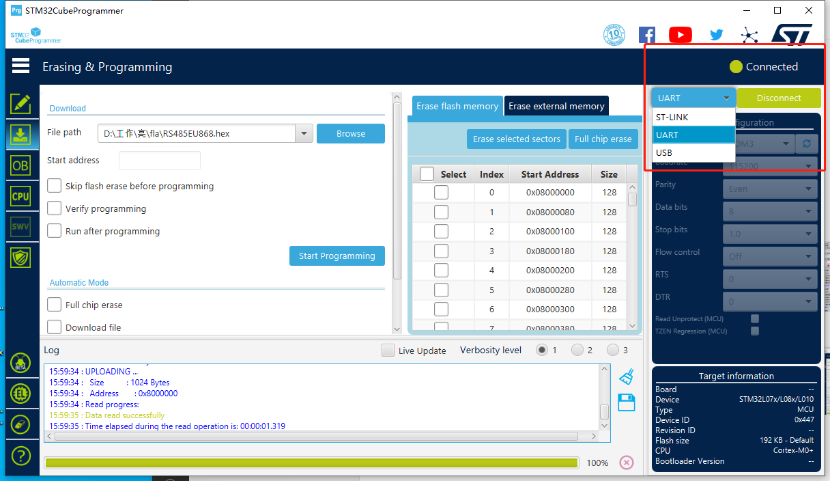
Step5: Select the file to download
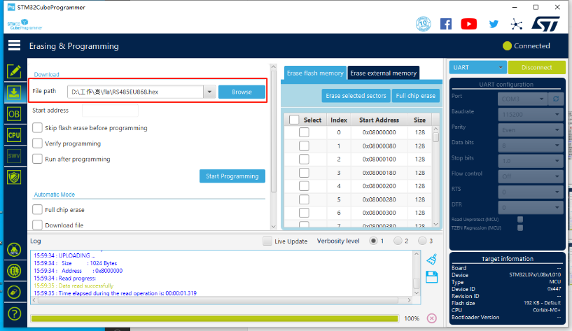
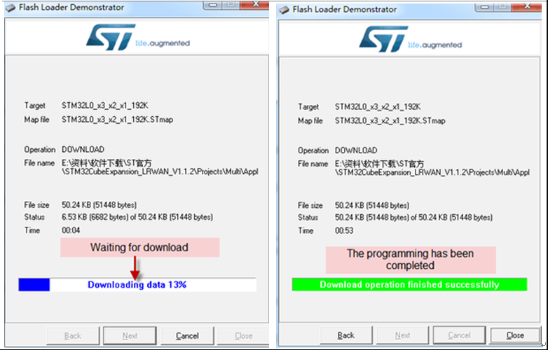
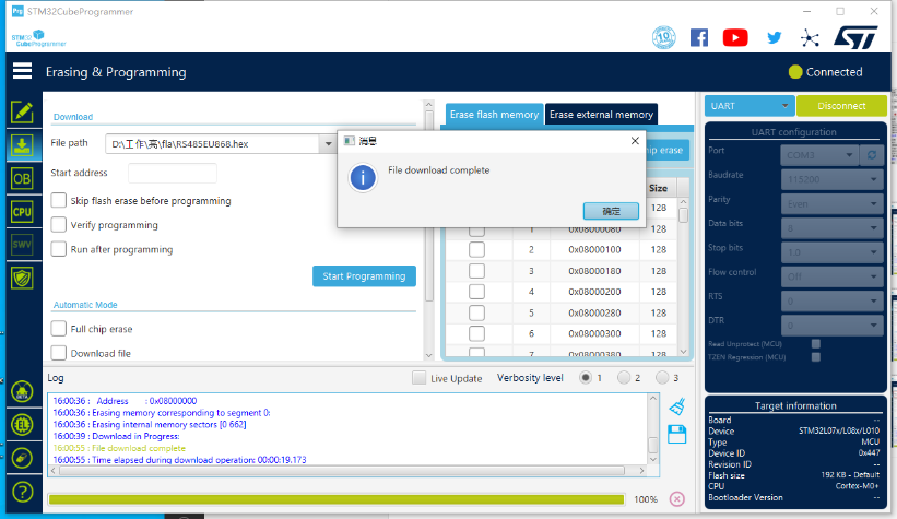
Step6: Click to start programming, and wait for it to download to 100%, pop up a successful download box
4.3 Trouble Shootings
4.3.1 ST-Link v2 can not detect the hardware
Possible Issue 1:
- Make sure see the LED blink on the ST-Link and release the reset button during blinking.
Possible Issue 2:
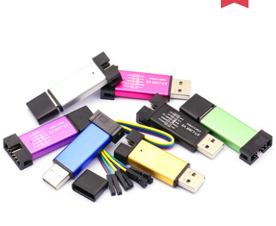
- There are different version ST-Link v2. The white one as below is the most stable and recommended one.
- The white version ST-Link v2 such as below photo has different hardware version. The original one doesn't have 3.3v on pin 1/2 and the clone one has 3.3v on pin 1/2. User has to short pin19 (VDD 3.3v) and pin 1/2 (TVCC) for the original one so pin 1/2 has 3.3v power. Otherwise, the original one might have problem to upload firmware to End Node.
ST-Link upload issue
Possible Issue 3:
- The ST-Link adapter has issue in the RESET pin. this happens for the LHT65 model where the update request use the reset pin of ST-Link.We see this issue happen in below ST-LINK.
RESET pin not function
User can try to mannual reset when use this type of ST-Link, touch the reset pin to GND pin and click the global icon in the ST Utility, If the other 3 wire connection is fine, the ST-LInk adapter LED will blink. and then release the reset. The IC should be detected.
For LHT65 we recommend to use the white one show in possible issue 2.
For LGT92, if user use this type of ST-Link, please also connect the 5v to USB port of LGT92.
4.3.2 ST-Link v2 detect the hardware but disconnect after click OK
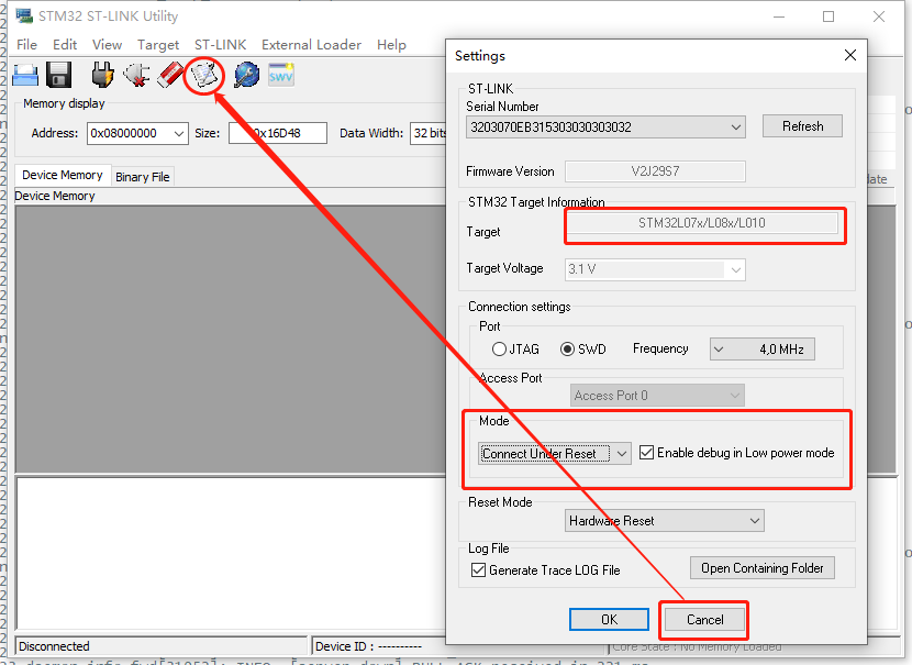
Do not click OK, click Cancel
4.3.3 Old ST-LINK firmware/ST-LINK already use and USB communication error
It may be that your stlink firmware is too old.
You can try these steps:
You unplug the stlink, and then plug in the stlink again.
You click ST-LINK -> Firmware update.
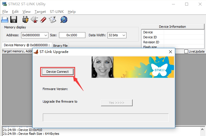
step1: click Device connect.
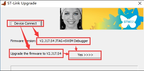
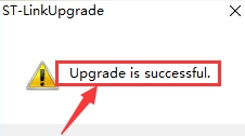
step2: Click yes to upgrade successfully.
5. Other Method
ST-Link v2 Upgrade Guide
Step 1: Install ST-LINK driver first and then install ST-LINK Utility
Step 2: Download the Image files, firmware download link can be found on the product user manual.
Step 3: Open ST-LINK utility, file --> open file to select the image to be upgraded.
Step 4:
- Case 1: If your board has the Reset pin connect to St-Link ((for example: LSN50v2, LHT65, LAQ4), click the blue global “settings” button on ST-LINK.
- Case 2: If your board doesn't have reset pin connect to ST-Link, but has a reset button (for example: LGT92). Keep pushing the small reset button on LGT92 and then click the blue global “settings” button on ST-Link utility.
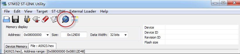
Click Global Icon
Step 5: Please select the mode as Connect under reset. After click the Global ICon in Step4, The led on the ST-LINK v2 adapter will now blinks, if you use hand to press the reset button , you need to release the reset button when see the LED blinks, and the ST-Link will detect the STM32 hardware as below. Click cancel to enter next step. Please check hardware connection if ST-Link v2 LED doesn't blink.

Do not click OK, click Cancel
Step 6: Click verify/upgrade firmware. The ST-Link utility will pop up a download window. Click the start button to download the image to Device.
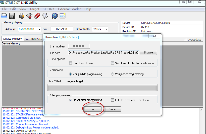
ST-Link v2 Upgrade