LHT65N LoRaWAN Temperature & Humidity Sensor Manual
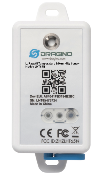
Table of Contents:
- 1. Introduction
- 2. Connect LHT65N to IoT Server
- 2.1 How does LHT65N work?
- 2.2 How to Activate LHT65N?
- 2.3 Example to join LoRaWAN network
- 2.4 Uplink Payload (Fport=2)
- 2.4.1 Decoder in TTN V3
- 2.4.2 BAT-Battery Info
- 2.4.3 Built-in Temperature
- 2.4.4 Built-in Humidity
- 2.4.5 Ext #
- 2.4.6 Ext value
- 2.4.6.1 Ext=1, E3 Temperature Sensor
- 2.4.6.2 Ext=9, E3 sensor with Unix Timestamp
- 2.4.6.3 Ext=6, ADC Sensor(use with E2 Cable)
- 2.4.6.4 Ext=2 TMP117 Sensor(Since Firmware v1.3)
- 2.4.6.5 Ext=11 SHT31 Sensor (Since Firmware v1.4.1)
- 2.4.6.6 Ext=4 Interrupt Mode(Since Firmware v1.3)
- 2.4.6.7 Ext=8 Counting Mode(Since Firmware v1.3)
- 2.4.6.8 Ext=10, E2 sensor (TMP117)with Unix Timestamp(Since firmware V1.3.2)
- 2.5 Show data on Datacake
- 2.6 Datalog Feature
- 2.7 Alarm Mode & Feature "Multi sampling, one uplink"
- 2.8 LED Indicator
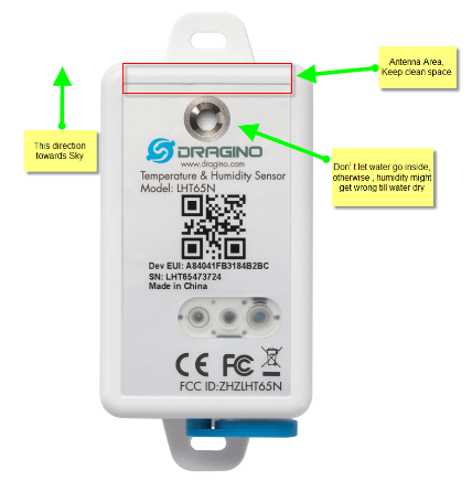
- 2.9 installation
- 3. Sensors and Accessories
- 4. Configure LHT65N via AT command or LoRaWAN downlink
- 4.1 Set Transmit Interval Time
- 4.2 Set External Sensor Mode
- 4.3 Enable/Disable uplink DS18B20 Temperature probe ID
- 4.4 Set Password
- 4.5 Quit AT Command
- 4.6 Set to sleep mode
- 4.7 Set system time
- 4.8 Set Time Sync Mode
- 4.9 Set Time Sync Interval
- 4.10 Get data
- 4.11 Print data entries base on page
- 4.12 Print last few data entries
- 4.13 Clear Flash Record
- 4.14 Auto Send None-ACK messages
- 4.15 Modified WMOD command for external sensor TMP117 or DS18B20 temperature alarm(Since firmware 1.3.0)
- 4.16 Get Firmware Version Info(Since V1.4.0)
- 4.17 Setting LEDAlarm
- 5. Battery & How to replace
- 6. FAQ
- 7. Order Info
- 8. Packing Info
- 9. Reference material
- 10. FCC Warning
1. Introduction
1.1 What is LHT65N LoRaWAN Temperature & Humidity Sensor
The Dragino LHT65N Temperature & Humidity sensor is a Long Range LoRaWAN Sensor. It includes a built-in Temperature & Humidity sensor and has an external sensor connector to connect to an external Temperature Sensor.
The LHT65N allows users to send data and reach extremely long ranges. It provides ultra-long range spread spectrum communication and high interference immunity whilst minimizing current consumption. It targets professional wireless sensor network applications such as irrigation systems, smart metering, smart cities, building automation, and so on.
LHT65N has a built-in 2400mAh non-chargeable battery which can be used for up to 10 years*.
LHT65N is full compatible with LoRaWAN v1.0.3 Class A protocol, it can work with a standard LoRaWAN gateway.
LHT65N supports Datalog Feature. It will record the data when there is no network coverage and users can retrieve the sensor value later to ensure no miss for every sensor reading.
*The actual battery life depends on how often to send data, please see the battery analyzer chapter.
1.2 Features
- LoRaWAN v1.0.3 Class A protocol
- Frequency Bands: CN470/EU433/KR920/US915/EU868/AS923/AU915
- AT Commands to change parameters
- Remote configure parameters via LoRaWAN Downlink
- Firmware upgradeable via program port
- Built-in 2400mAh battery for up to 10 years of use.
- Built-in Temperature & Humidity sensor
- Optional External Sensors
- Tri-color LED to indicate working status
- Datalog feature (Max 3328 records)
1.3 Specification
Built-in Temperature Sensor:
- Resolution: 0.01 °C
- Accuracy Tolerance : Typ ±0.3 °C
- Long Term Drift: < 0.02 °C/yr
- Operating Range: -40 ~ 85 °C
Built-in Humidity Sensor:
- Resolution: 0.04 %RH
- Accuracy Tolerance : Typ ±3 %RH
- Long Term Drift: < 0.25 RH/yr
- Operating Range: 0 ~ 96 %RH
External Temperature Sensor:
- Resolution: 0.0625 °C
- ±0.5°C accuracy from -10°C to +85°C
- ±2°C accuracy from -55°C to +125°C
- Operating Range: -55 °C ~ 125 °C
2. Connect LHT65N to IoT Server
2.1 How does LHT65N work?
LHT65N is configured as LoRaWAN OTAA Class A mode by default. Each LHT65N is shipped with a worldwide unique set of OTAA keys. To use LHT65N in a LoRaWAN network, first, we need to put the OTAA keys in LoRaWAN Network Server and then activate LHT65N.
If LHT65N is under the coverage of this LoRaWAN network. LHT65N can join the LoRaWAN network automatically. After successfully joining, LHT65N will start to measure environment temperature and humidity, and start to transmit sensor data to the LoRaWAN server. The default period for each uplink is 20 minutes.
2.2 How to Activate LHT65N?
The LHT65N has two working modes:
Deep Sleep Mode: LHT65N doesn't have any LoRaWAN activation. This mode is used for storage and shipping to save battery life.
Working Mode: In this mode, LHT65N works as LoRaWAN Sensor mode to Join LoRaWAN network and send out the sensor data to the server. Between each sampling/tx/rx periodically, LHT65N will be in STOP mode (IDLE mode), in STOP mode, LHT65N has the same power consumption as Deep Sleep mode.
The LHT65N is set in deep sleep mode by default; The ACT button on the front is to switch to different modes:
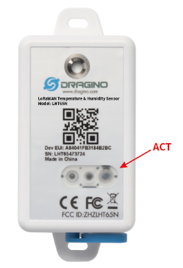
| Behavior on ACT | Function | Action |
|---|---|---|
| Pressing ACT between 1s < time < 3s | Test uplink status | If LHT65N is already Joined to rhe LoRaWAN network, LHT65N will send an uplink packet, if LHT65N has external sensor connected,Blue led will blink once. If LHT65N has not external sensor, Red led will blink once. |
| Pressing ACT for more than 3s | Active Device | Green led will fast blink 5 times, LHT65N will enter working mode and start to JOIN LoRaWAN network. |
| Fast press ACT 5 times. | Deactivate Device | Red led will solid on for 5 seconds. Means LHT65N is in Deep Sleep Mode. |
2.3 Example to join LoRaWAN network
This section shows an example of how to join the TTN V3 LoRaWAN IoT server. Use with other LoRaWAN IoT servers is of a similar procedure.
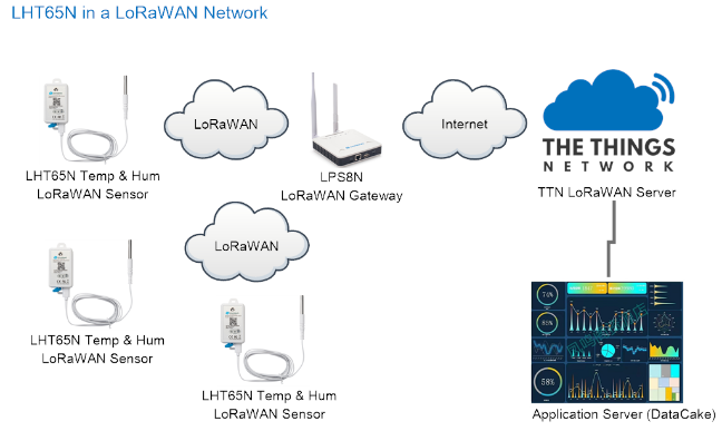
Assume the LPS8N is already set to connect to TTN V3 network, So it provides network coverage for LHT65N. Next we need to add the LHT65N device in TTN V3:
2.3.1 Step 1: Create Device on TTN
Create a device in TTN V3 with the OTAA keys from LHT65N.
Each LHT65N is shipped with a sticker with its device EUI, APP Key and APP EUI as below:
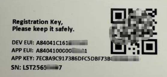
User can enter these keys in the LoRaWAN Server portal. Below is TTN V3 screenshot:
Add APP EUI in the application.
1. Create application
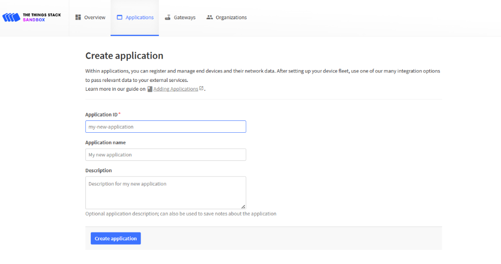
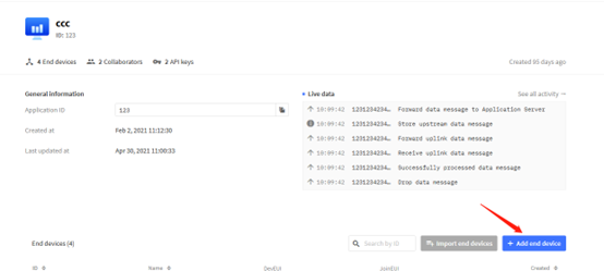
2. Register end device

Note: LHT65N use same payload as LHT65.
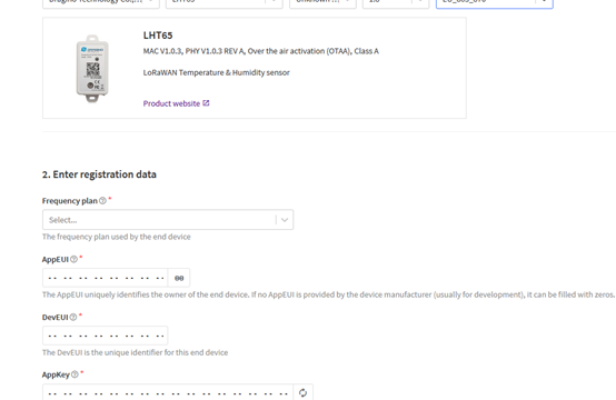
Input JoinEUI(APPEUI), DEVEUI and APPKEY:

2.3.2 Step 2: Activate LHT65N by pressing the ACT button for more than 5 seconds.
Use ACT button to activate LHT65N and it will auto-join to the TTN V3 network. After join success, it will start to upload sensor data to TTN V3 and user can see in the panel.

2.4 Uplink Payload (Fport=2)
The uplink payload includes totally 11 bytes. Uplink packets use FPORT=2 and every 20 minutes send one uplink by default.
After each uplink, the BLUE LED will blink once.
Size(bytes) | 2 | 2 | 2 | 1 | 4 |
|---|---|---|---|---|---|
Value | Ext # |
- The First 6 bytes: has fix meanings for every LHT65N.
- The 7th byte (EXT #): defines the external sensor model.
- The 8th ~ 11th byte: the value for external sensor value. The definition is based on external sensor type. (If EXT=0, there won't be these four bytes.)
2.4.1 Decoder in TTN V3
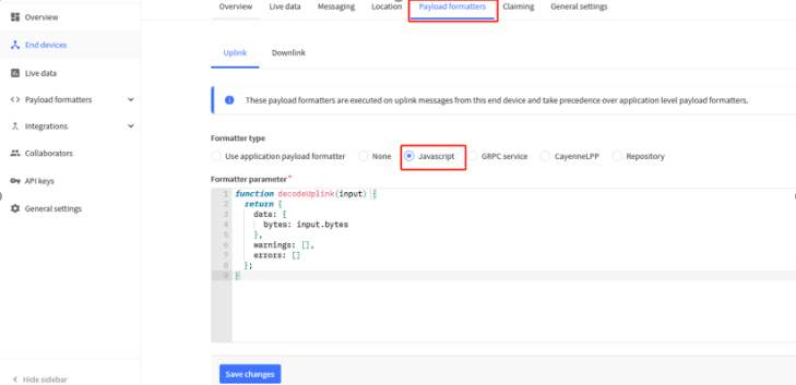
When the uplink payload arrives TTNv3, it shows HEX format and not friendly to read. We can add LHT65N decoder in TTNv3 for friendly reading.
Below is the position to put the decoder and LHT65N decoder can be download from here: https://github.com/dragino/dragino-end-node-decoder
2.4.2 BAT-Battery Info
These two bytes of BAT include the battery state and the actually voltage.
Bit(bit) | [15:14] | [13:0] |
|---|---|---|
Value | BAT Status | Actually BAT voltage |
(b)stands for binary

Check the battery voltage for LHT65N.
- BAT status=(0Xcba4>>14)&0xFF=11 (BIN) ,very good
- Battery Voltage =0xCBA4&0x3FFF=0x0BA4=2980mV
2.4.3 Built-in Temperature

- Temperature: 0x0ABB/100=27.47℃

- Temperature: (0xF5C6-65536)/100=-26.18℃
2.4.4 Built-in Humidity

- Humidity: 0x025C/10=60.4%
2.4.5 Ext #
Bytes for External Sensor:
| EXT # Value | External Sensor Type |
|---|---|
| 0x01 | Sensor E3, Temperature Sensor |
| 0x09 | Sensor E3, Temperature Sensor, Datalog Mod |
| 0x06 | ADC Sensor(use with E2 Cable) |
| 0x02 | TMP117 Sensor |
| 0x11 | SHT31 Sensor |
| 0x04 | Interrupt Mode |
| 0x08 | Counting Mode |
| 0x10 | E2 sensor (TMP117)with Unix Timestamp |
2.4.6 Ext value
2.4.6.1 Ext=1, E3 Temperature Sensor
Size(bytes) | 2 | 2 | 2 | 1 | 2 | 2 |
|---|---|---|---|---|---|---|
Value | BAT & BAT Status | TempC_SHT | Hum_SHT | Status & Ext | TempC_DS | senseless |

- DS18B20 temp=0x0ADD/100=27.81℃
The last 2 bytes of data are meaningless

- External temperature= (0xF54F-65536)/100=-27.37℃
F54F : (F54F & 8000 == 1) , temp = (F54F - 65536)/100 = 27.37℃
(0105 & 8000:Judge whether the highest bit is 1, when the highest bit is 1, it is negative)
The last 2 bytes of data are meaningless
If the external sensor is 0x01, and there is no external temperature connected. The temperature will be set to 7FFF which is 327.67℃
2.4.6.2 Ext=9, E3 sensor with Unix Timestamp
Timestamp mode is designed for LHT65N with E3 probe, it will send the uplink payload with Unix timestamp. With the limitation of 11 bytes (max distance of AU915/US915/AS923 band), the time stamp mode will be lack of BAT voltage field, instead, it shows the battery status. The payload is as below:
Size(bytes) | 2 | 2 | 2 | 1 | 4 |
|---|---|---|---|---|---|
Value | External temperature | BAT Status & Built-in Humidity | Status & Ext |
- Battery status & Built-in Humidity
| Bit(bit) | [15:14] | [11:0] |
|---|---|---|
| Value | BAT Status |
- Status & Ext Byte
| Bits | 7 | 6 | 5 | 4 | [3:0] |
| Status&Ext | None-ACK Flag | Poll Message FLAG | Sync time OK | Unix Time Request | Ext: 0b(1001) |
- Poll Message Flag: 1: This message is a poll message reply, 0: means this is a normal uplink.
- Sync time OK: 1: Set time ok,0: N/A. After time SYNC request is sent, LHT65N will set this bit to 0 until got the time stamp from the application server.
- Unix Time Request: 1: Request server downlink Unix time, 0 : N/A. In this mode, LHT65N will set this bit to 1 every 10 days to request a time SYNC. (AT+SYNCMOD to set this)
2.4.6.3 Ext=6, ADC Sensor(use with E2 Cable)
Size(bytes) | 2 | 2 | 2 | 1 | 2 | 2 |
|---|---|---|---|---|---|---|
Value | BAT & BAT Status | TempC_SHT | Hum_SHT | Status & Ext | ADC_Value | senseless |
In this mode, user can connect external ADC sensor to check ADC value. The 3V3_OUT can
be used to power the external ADC sensor; user can control the power on time for this
sensor by setting:
AT+EXT=6,timeout Time to power this sensor, from 0 ~ 65535ms
For example:
AT+EXT=6,1000 will power this sensor for 1000ms before sampling the ADC value.
Or use downlink command A2 to set the same.
The measuring range of the node is only about 0.1V to 1.1V The voltage resolution is about 0.24mv.
When the measured output voltage of the sensor is not within the range of 0.1V and 1.1V, the output voltage terminal of the sensor shall be divided The example in the following figure is to reduce the output voltage of the sensor by three times If it is necessary to reduce more times, calculate according to the formula in the figure and connect the corresponding resistance in series.
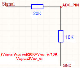
When ADC_IN1 pin is connected to GND or suspended, ADC value is 0

When the voltage collected by ADC_IN1 is less than the minimum range, the minimum range will be used as the output; Similarly, when the collected voltage is greater than the maximum range, the maximum range will be used as the output.
1) The minimum range is about 0.1V. Each chip has internal calibration, so this value is close to 0.1V

2) The maximum range is about 1.1V. Each chip has internal calibration, so this value is close to 1.1v

3) Within range

2.4.6.4 Ext=2 TMP117 Sensor(Since Firmware v1.3)

Ext=2,Temperature Sensor(TMP117):
Size(bytes) | 2 | 2 | 2 | 1 | 2 | 2 |
|---|---|---|---|---|---|---|
Value | BAT & BAT Status | TempC_SHT | Hum_SHT | Status & Ext | TempC_Temp117 | senseless |

Interrupt Mode and Counting Mode:
The external cable NE2 can be use for MOD4 and MOD8
2.4.6.5 Ext=11 SHT31 Sensor (Since Firmware v1.4.1)

Ext=11,Temperature & Humidity Sensor(SHT31):
Size(bytes) | 2 | 2 | 2 | 1 | 2 | 2 |
|---|---|---|---|---|---|---|
Value | BAT & BAT Status | TempC_SHT | Hum_SHT | Status & Ext | Ext_TempC_SHT | Ext_Hum_SHT |

2.4.6.6 Ext=4 Interrupt Mode(Since Firmware v1.3)
Note: In this mode, 3.3v output will be always ON. LHT65N will send an uplink when there is a trigger.
Interrupt Mode can be used to connect to external interrupt sensors such as:
Case 1: Door Sensor. 3.3v Out for such sensor is just to detect Open/Close.
In Open State, the power consumption is the same as if there is no probe
In Close state, the power consumption will be 3uA higher than normal.
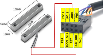
Ext=4,Interrupt Sensor:
AT+EXT=4,1 | Sent uplink packet in both rising and falling interrupt |
AT+EXT=4,2 | Sent uplink packet only in falling interrupt |
AT+EXT=4,3 | Sent uplink packet only in rising interrupt |
Size(bytes) | 2 | 2 | 2 | 1 | 1 | 1 | 2 |
|---|---|---|---|---|---|---|---|
Value | BAT & BAT Status | TempC_SHT | Hum_SHT | Status & Ext | Exti_pin_level | Exti_status | senseless |
Trigger by falling edge:

Trigger by raising edge:

BAT & BAT Status :
Check the battery voltage.
Ex1: 0x0B45 = 2885mV
Ex2: 0x0B49 = 2889mV
TempC_SHT :
The temperature detected by the built-in temperature and humidity sensor SHT31.
If payload is: 0105H: (0105 & 8000 == 0), temp = 0105H /10 = 26.1 degree
If payload is: FF3FH : (FF3F & 8000 == 1) , temp = (FF3FH - 65536)/10 = -19.3 degrees.
(FF3F & 8000: Judge whether the highest bit is 1, when the highest bit is 1, it is negative)
Hum_SHT :
The humidity detected by the built-in temperature and humidity sensor SHT31.
Read:0295(H)=661(D) Value: 661 / 10=66.1, So 66.1%
Status & Ext :
| Bits | 7 | 6 | 5 | 4 | [3:0] |
| Status&Ext | None-ACK Flag | Poll Message FLAG | Sync time OK | Unix Time Request | Ext: 0b(1001) |
- Poll Message Flag: 1: This message is a poll message reply, 0: means this is a normal uplink.
- Sync time OK: 1: Set time ok,0: N/A. After time SYNC request is sent, LHT65N will set this bit to 0 until got the time stamp from the application server.
- Unix Time Request: 1: Request server downlink Unix time, 0 : N/A. In this mode, LHT65N will set this bit to 1 every 10 days to request a time SYNC. (AT+SYNCMOD to set this)
Exti_pin_level :
- Wet contacts: high and low levels . 1: high level; 0: low level.
- Dry contacts: 1: closed; 0: open
Exti_status :
Determines whether the uplink packet is generated by an interrupt.
1: Interrupt packet
0: Normal TDC uplink packet
senseless :
Reserved position, meaningless. The value is fixed to 0x7FFF.
2.4.6.7 Ext=8 Counting Mode(Since Firmware v1.3)
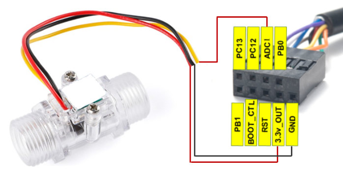
Note: In this mode, 3.3v output will be always ON. LHT65N will count for every interrupt and uplink periodically.
Case 1: Low power consumption Flow Sensor, such flow sensor has pulse output and the power consumption in uA level and can be powered by LHT65N.
Case 2: Normal Flow Sensor: Such flow sensor has higher power consumption and is not suitable to be powered by LHT65N. It is powered by external power and output <3.3v pulse
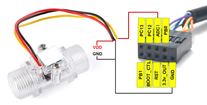
Ext=8, Counting Sensor ( 4 bytes):
AT+EXT=8,0 | Count at falling interrupt |
AT+EXT=8,1 | Count at rising interrupt |
AT+SETCNT=60 | Sent current count to 60 |
Size(bytes) | 2 | 2 | 2 | 1 | 4 |
|---|---|---|---|---|---|
Value | BAT & BAT Status | TempC_SHT | Hum_SHT | Status & Ext | Exit_count |

A2 downlink Command:
A2 02: Same as AT+EXT=2 (AT+EXT= second byte)
A2 06 01 F4: Same as AT+EXT=6,500 (AT+EXT= second byte, third and fourth bytes)
A2 04 02: Same as AT+EXT=4,2 (AT+EXT= second byte, third byte)
A2 08 01 00: Same as AT+EXT=8,0 (AT+EXT= second byte, fourth byte)
A2 08 02 00 00 00 3C: Same as AT+ SETCNT=60 (AT+ SETCNT = 4th byte and 5th byte and 6th byte and 7th byte)
2.4.6.8 Ext=10, E2 sensor (TMP117)with Unix Timestamp(Since firmware V1.3.2)
Timestamp mode is designed for LHT65N with E2 probe, it will send the uplink payload with Unix timestamp. With the limitation of 11 bytes (max distance of AU915/US915/AS923 band), the time stamp mode will be lack of BAT voltage field, instead, it shows the battery status. The payload is as below:
Size(bytes) | 2 | 2 | 2 | 1 | 4 |
|---|---|---|---|---|---|
Value | External temperature | BAT Status & Built-in Humidity | Status & Ext |
- Battery status & Built-in Humidity
| Bit(bit) | [15:14] | [11:0] |
|---|---|---|
| Value | BAT Status |
- Status & Ext Byte
| Bits | 7 | 6 | 5 | 4 | [3:0] |
| Status&Ext | None-ACK Flag | Poll Message FLAG | Sync time OK | Unix Time Request | Ext: 0b(1001) |
- Poll Message Flag: 1: This message is a poll message reply, 0: means this is a normal uplink.
- Sync time OK: 1: Set time ok, 0: N/A. After time SYNC request is sent, LHT65N will set this bit to 0 until got the time stamp from the application server.
- Unix Time Request: 1: Request server downlink Unix time, 0 : N/A. In this mode, LHT65N will set this bit to 1 every 10 days to request a time SYNC. (AT+SYNCMOD to set this)
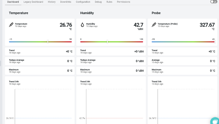
2.5 Show data on Datacake
Datacake IoT platform provides a human-friendly interface to show the sensor data, once we have sensor data in TTN V3, we can use Datacake to connect to TTN V3 and see the data in Datacake. Below are the steps:
Step 1: Be sure that your device is programmed and properly connected to the LoRaWAN network.
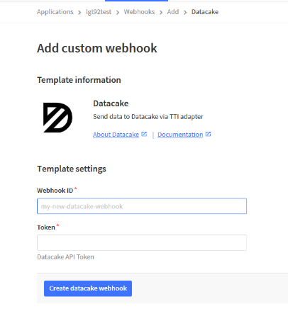
Step 2: Configure your Application to forward data to Datacake you will need to add integration. Go to TTN V3 Console --> Applications --> Integrations --> Add Integrations.
Add Datacake:

Select default key as Access Key:
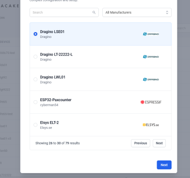
In Datacake console (https://datacake.co/) , add LHT65 device.
2.6 Datalog Feature
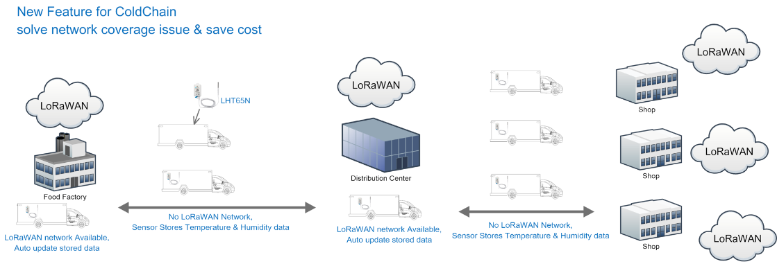
Datalog Feature is to ensure IoT Server can get all sampling data from Sensor even if the LoRaWAN network is down. For each sampling, LHT65N will store the reading for future retrieving purposes. There are two ways for IoT servers to get datalog from LHT65N.
2.6.1 Ways to get datalog via LoRaWAN
There are two methods:
Method 1: IoT Server sends a downlink LoRaWAN command to poll the value for specified time range.
Method 2: Set PNACKMD=1, LHT65N will wait for ACK for every uplink, when there is no LoRaWAN network, LHT65N will mark these records with non-ack messages and store the sensor data, and it will send all messages (10s interval) after the network recovery.
Note for method 2:
- a) LHT65N will do an ACK check for data records sending to make sure every data arrive server.
- b) LHT65N will send data in CONFIRMED Mode when PNACKMD=1, but LHT65N won't re-transmit the packet if it doesn't get ACK, it will just mark it as a NONE-ACK message. In a future uplink if LHT65N gets a ACK, LHT65N will consider there is a network connection and resend all NONE-ACK Message.
Below is the typical case for the auto-update datalog feature (Set PNACKMD=1)
2.6.2 Unix TimeStamp
LHT65N uses Unix TimeStamp format based on

User can get this time from link: https://www.epochconverter.com/ :
Below is the converter example
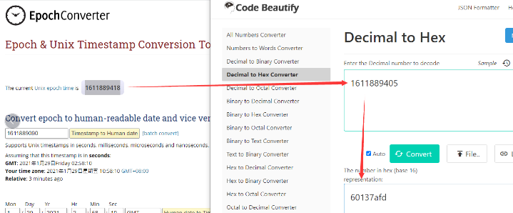
So, we can use AT+TIMESTAMP=1611889405 or downlink 3060137afd00 to set the current time 2021 – Jan -- 29 Friday 03:03:25
2.6.3 Set Device Time
There are two ways to set device's time:
1. Through LoRaWAN MAC Command (Default settings)
User need to set SYNCMOD=1 to enable sync time via MAC command.
Once LHT65N Joined LoRaWAN network, it will send the MAC command (DeviceTimeReq) and the server will reply with (DeviceTimeAns) to send the current time to LHT65N. If LHT65N fails to get the time from the server, LHT65N will use the internal time and wait for next time request (AT+SYNCTDC to set the time request period, default is 10 days).
Note: LoRaWAN Server need to support LoRaWAN v1.0.3(MAC v1.0.3) or higher to support this MAC command feature, Chirpstack,TTN V3 v3 and loriot support but TTN V3 v2 doesn't support. If server doesn't support this command, it will through away uplink packet with this command, so user will lose the packet with time request for TTN V3 v2 if SYNCMOD=1.
2. Manually Set Time
User needs to set SYNCMOD=0 to manual time, otherwise, the user set time will be overwritten by the time set by the server.
2.6.4 Poll sensor value
User can poll sensor value based on timestamps from the server. Below is the downlink command.
| 1byte | 4bytes | 4bytes | 1byte |
| 31 | Timestamp start | Timestamp end | Uplink Interval |
Timestamp start and Timestamp end use Unix TimeStamp format as mentioned above. Devices will reply with all data log during this time period, use the uplink interval.
For example, downlink command 31 5FC5F350 5FC6 0160 05
Is to check 2020/12/1 07:40:00 to 2020/12/1 08:40:00's data
Uplink Internal =5s, means LHT65N will send one packet every 5s. range 5~255s.
2.6.5 Datalog Uplink payload
The Datalog poll reply uplink will use below payload format.
Retrieval data payload:
Size(bytes) | 2 | 2 | 2 | 1 | 4 |
|---|---|---|---|---|---|
| Value | External sensor data | Built In Temperature | Built-in Humidity | Poll message flag & Ext | Unix Time Stamp |
Poll message flag & Ext:
| Bits | 7 | 6 | 5 | 4 | [3:0] |
| Status&Ext | No ACK Message | Poll Message Flag | Sync time OK | Unix Time Request | Ext: 0b(1001) |
No ACK Message: 1: This message means this payload is fromn Uplink Message which doesn't get ACK from the server before ( for PNACKMD=1 feature)
Poll Message Flag: 1: This message is a poll message reply.
- Poll Message Flag is set to 1.
- Each data entry is 11 bytes, to save airtime and battery, devices will send max bytes according to the current DR and Frequency bands.
For example, in US915 band, the max payload for different DR is:
a) DR0: max is 11 bytes so one entry of data
b) DR1: max is 53 bytes so devices will upload 4 entries of data (total 44 bytes)
c) DR2: total payload includes 11 entries of data
d) DR3: total payload includes 22 entries of data.
If devise doesn't have any data in the polling time. Device will uplink 11 bytes of 0
Example:
If LHT65N has below data inside Flash:
| Flash Add | Unix Time | Ext | BAT voltage | Value |
|---|---|---|---|---|
| 80196E0 | 21/1/19 04:27:03 | 1 | 3145 | sht temp=22.00 sht hum=32.6 ds temp=327.67 |
| 80196F0 | 21/1/19 04:28:57 | 1 | 3145 | sht temp=21.90 sht hum=33.1 ds temp=327.67 |
| 8019600 | 21/1/19 04:30:30 | 1 | 3145 | sht temp=21.81 sht hum=33.4 ds temp=327.67 |
| 8019610 | 21/1/19 04:40:30 | 1 | 3145 | sht temp=21.65 sht hum=33.7 ds temp=327.67 |
| 8019620 | 21/1/19 04:50:30 | 1 | 3147 | sht temp=21.55 sht hum=34.1 ds temp=327.67 |
| 8019630 | 21/1/19 04:00:30 | 1 | 3149 | sht temp=21.50 sht hum=34.1 ds temp=327.67 |
| 8019640 | 21/1/19 04:10:30 | 1 | 3149 | sht temp=21.43 sht hum=34.6 ds temp=327.67 |
| 8019650 | 21/1/19 04:20:30 | 1 | 3151 | sht temp=21.35 sht hum=34.9 ds temp=327.67 |
If user sends below downlink command: 3160065F9760066DA705
Where : Start time: 60065F97 = time 21/1/19 04:27:03
Stop time: 60066DA7= time 21/1/19 05:27:03
LHT65N will uplink this payload.
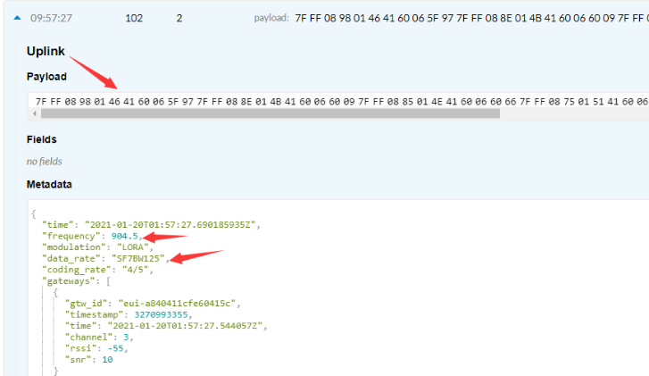
7FFF089801464160065F97 7FFF 088E 014B 41 60066009 7FFF0885014E41600660667FFF0875015141600662BE7FFF086B015541600665167FFF08660155416006676E7FFF085F015A41600669C67FFF0857015D4160066C1E
Where the first 11 bytes is for the first entry:
7FFF089801464160065F97
Ext sensor data=0x7FFF/100=327.67
Temp=0x088E/100=22.00
Hum=0x014B/10=32.6
poll message flag & Ext=0x41,means reply data,Ext=1
Unix time is 0x60066009=1611030423s=21/1/19 04:27:03
2.7 Alarm Mode & Feature "Multi sampling, one uplink"
when the device is in alarm mode, it checks the built-in sensor temperature for a short time. if the temperature exceeds the preconfigured range, it sends an uplink immediately.
Note: alarm mode adds a little power consumption, and we recommend extending the normal read time when this feature is enabled.
2.7.1 ALARM MODE ( Since v1.3.1 firmware)
DS18B20 and TMP117 Threshold Alarm(The mod1 use for external sensors (DS18B20 and TMP117 )
AT+WMOD=1,60,-10,20
Explain:
- parameter1: Set Working Mode to Mode 1,Threshold Alarm(Out of range alarm)
- parameter2: Sampling Interval is 60s.
- parameter3 & parameter4: Temperature alarm range is -10 to 20°C(Set the temperature range value with a coefficient of 100)
Downlink Command:
Example: A5013CFC1807D0
MOD=01
CITEMP=3C(S) =60(S)
TEMPlow=FC18 = -1000/100=-10(℃)
TEMPhigh=07D0=2000/100=20(℃)
Fluctuation alarm for DS18B20 and TMP117(Acquisition time: minimum 1s)(The mod2 use for external sensors (DS18B20 and TMP117)
AT+WMOD=2,60,5
Explain:
- parameter1: Set Working Mode to Mode 2,Fluctuation alarm
- parameter2: Sampling Interval is 60s.
- parameter3: The temperature fluctuation is +-5 °C
Downlink Command
Example: A5023C05
MOD=02
CITEMP=3C(S)=60(S)
temperature fluctuation=05(℃)
Sampling multiple times and uplink together(The mod3 can be used for internal and external sensors)(Internal GXHT30 temperature alarm(Acquisition time: fixed at one minute)
AT+WMOD=3,1,60,20,-16,32,1
Explain:
- parameter1: Set Working Mode to Mode 3,Sampling multiple times and uplink together
- parameter2: Set the temperature sampling mode to 1(1:DS18B20;2:TMP117;3: Internal GXHT30).
- parameter3: Sampling Interval is 60s.(This parameter has no effect on internal sensors)
- parameter4: When there is 20 sampling dats, Device will send these data via one uplink. (max value is 60, means max 60 sampling in one uplink)
- parameter5 & parameter6: Temperature alarm range is -16 to 32°C,
- parameter7: 1 to enable temperature alarm, 0 to disable the temperature alarm. If alarm is enabled, a data will be sent immediately if temperate exceeds the Alarm range.
Downlink Command:
Example: A50301003C14FFF0002001
MOD=03
TEMP=DS18B20
CITEMP=003C(S)=60(S)
Total number of acquisitions=14
TEMPlow=FFF0=-16(℃)
TEMPhigh=0020=20(℃)
ARTEMP=01
Uplink payload( Fport=3)
Example: CBEA0109920A4109C4
BatV=CBEA
TEMP=DS18B20
Temp1=0992 // 24.50℃
Temp2=0A41 // 26.25℃
Temp3=09C4 // 25.00℃
Note: This uplink will automatically select the appropriate DR according to the data length
In this mode, the temperature resolution of ds18b20 is 0.25℃ to save power consumption
2.7.2 ALARM MODE ( Before v1.3.1 firmware)
Downlink Command: AAXXXXXXXXXXXXXX
Total bytes: 8 bytes
Example:AA0100010001003C
WMOD=01
CITEMP=0001
TEMPlow=0001
TEMPhigh=003C
2.8 LED Indicator
The LHT65 has a triple color LED which for easy showing different stage .
While user press ACT button, the LED will work as per LED status with ACT button.
In a normal working state:
- For each uplink, the BLUE LED or RED LED will blink once.
BLUE LED when external sensor is connected. - RED LED when external sensor is not connected
- For each success downlink, the PURPLE LED will blink once
2.9 installation
3. Sensors and Accessories
3.1 E2 Extension Cable
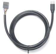
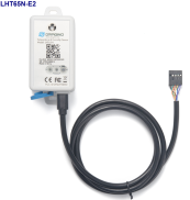
1m long breakout cable for LHT65N. Features:
Use for AT Command, works for both LHT52/LHT65N
Update firmware for LHT65N, works for both LHT52/LHT65N
Supports ADC mode to monitor external ADC
Supports Interrupt mode
Exposed All pins from the LHT65N Type-C connector.
3.2 E3 Temperature Probe
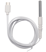
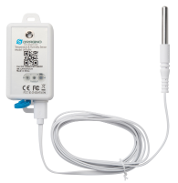
Temperature sensor with 2 meters cable long
- Resolution: 0.0625 °C
- ±0.5°C accuracy from -10°C to +85°C
- ±2°C accuracy from -55°C to +125°C
- Operating Range: -40 ~ 125 °C
- Working voltage 2.35v ~ 5v
3.3 E31F Temperature Probe
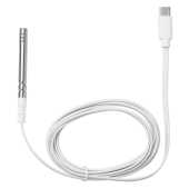
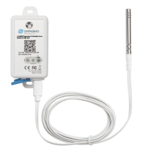
Temperature sensor with 1 meters cable long
Built-in Temperature Sensor:
- Resolution: 0.01 °C
- Accuracy Tolerance : Typ ±0.3 °C
- Long Term Drift: < 0.02 °C/yr
- Operating Range: -40 ~ 80 °C
Built-in Humidity Sensor:
- Resolution: 0.04 % RH
- Accuracy Tolerance : Typ ±3 % RH
- Long Term Drift: < 0.02 °C/yr
- Operating Range: 0 ~ 96 % RH
External Temperature Sensor :
- Resolution: 0.01 °C
- Accuracy Tolerance : Typical ±0.3 °C
- Long Term Drift: < 0.02 °C/yr
- Operating Range: -40 ~ 125 °C
External Humidity Sensor :
- Resolution: 0.04 % RH
- Accuracy Tolerance : Typ ±3 % RH
- Long Term Drift: < 0.02 °C/yr
- Operating Range: 0 ~ 96 % RH
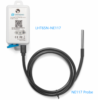
3.4 NE117 Temperature Probe (Model: LHT65N-NE117)
External Temperature Sensor – NE117:
Equip with TMP117A temperature sensor. TMP117 IC is NIST traceability Sensor by TI.
- Silica gel cable
- ±0.1 °C (maximum) from –20 °C to 50 °C
- ±0.2 °C (maximum) from –40 °C to 100 °C
- ±0.3 °C (maximum) from –55 °C to 150 °C
3.5 Dry Contact Probe (Model: LHT65N-DC)
- Design for Pulse Counting(Ext=8), Alarm (Ext=4),Open/Close Detect (Ext=4)
- 3 wires: VCC/GND/INT
- Cable Lenght: 1 meter

LHT65-DC can be used to connect various types of external sensor. below.
User can refer this link for the instructions: LHT65-DC Connection Instruction.


3.6 Door Sensor (Model: LHT65N-DS)
- Aluminum Alloy Door Sensor
- Detect Distance: ~3cm
- Cable Lenght: 1 meter
Notice: When order LHT65N-DS, the device is by default set to: a) AT+EXT=4,1 ; b) Default Uplink Interval TDC is 12 hour.

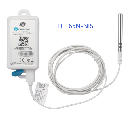
3.6 NIS Certificate Probe (Model: LHT65N-NIS)
External Probe:
- Unique NIST Certi cate for each probe
- External NIST Traceable probe with unique ID
Notice: AT+PID=1 is by default enable, so LHT65N will also uplink the probe ID to platform.
4. Configure LHT65N via AT command or LoRaWAN downlink
Use can configure LHT65N via AT Command or LoRaWAN Downlink.
AT Command Connection: See FAQ.
LoRaWAN Downlink instruction for different platforms: IoT LoRaWAN Server
There are two kinds of commands to configure LHT65N, they are:
General Commands.
These commands are to configure:
General system settings like: uplink interval.
LoRaWAN protocol & radio-related commands.
They are the same for all Dragino Devices which supports DLWS-005 LoRaWAN Stack(Note**). These commands can be found on the wiki: End Device Downlink Command
Commands special design for LHT65N
These commands are only valid for LHT65N, as below:
4.1 Set Transmit Interval Time
Feature: Change LoRaWAN End Node Transmit Interval.
AT Command: AT+TDC
| Command Example | Function | Response |
| AT+TDC=? | Show current transmit Interval | 30000 OK the interval is 30000ms = 30s |
| AT+TDC=60000 | Set Transmit Interval | OK Set transmit interval to 60000ms = 60 seconds |
Downlink Command: 0x01
Format: Command Code (0x01) followed by 3 bytes time value.
If the downlink payload=0100003C, it means set the END Node's Transmit Interval to 0x00003C=60(S), while type code is 01.
- Example 1: Downlink Payload: 0100001E // Set Transmit Interval (TDC) = 30 seconds
- Example 2: Downlink Payload: 0100003C // Set Transmit Interval (TDC) = 60 seconds
4.2 Set External Sensor Mode
Feature: Change External Sensor Mode.
AT Command: AT+EXT
| Command Example | Function | Response |
| AT+EXT=? | Get current external sensor mode | 1 OK External Sensor mode =1 |
| AT+EXT=1 | Set external sensor mode to 1 | |
| AT+EXT=9 | Set to external DS18B20 with timestamp | |
Downlink Command: 0xA2
Total bytes: 2 ~ 5 bytes
Example:
- 0xA201: Set external sensor type to E1
- 0xA209: Same as AT+EXT=9
- 0xA20702003c: Same as AT+SETCNT=60
4.3 Enable/Disable uplink DS18B20 Temperature probe ID
Feature: If PID is enabled, LHT65N will send the DS18B20 temperature probe ID on:
- First Packet after OTAA Join
- Every 24 hours since the first packet.
PID is default set to disable (0)
Notice: This feature only valid when EXT=1 or EXt=9
AT Command:
| Command Example | Function | Response |
| AT+PID=1 | Enable PID uplink | OK |
Downlink Command:
- 0xA800 --> AT+PID=0
- 0xA801 --> AT+PID=1
4.4 Set Password
Feature: Set device password, max 9 digits
AT Command: AT+PWORD
| Command Example | Function | Response |
| AT+PWORD=? | Show password | 123456 OK |
| AT+PWORD=999999 | Set password | OK |
Downlink Command:
No downlink command for this feature.
4.5 Quit AT Command
Feature: Quit AT Command mode, so user needs to input password again before use AT Commands.
AT Command: AT+DISAT
| Command Example | Function | Response |
| AT+DISAT | Quit AT Commands mode | OK |
Downlink Command:
No downlink command for this feature.
4.6 Set to sleep mode
Feature: Set device to sleep mode
- AT+Sleep=0 : Normal working mode, device will sleep and use lower power when there is no LoRa message
- AT+Sleep=1 : Device is in deep sleep mode, no LoRa activation happen, used for storage or shipping.
AT Command: AT+SLEEP
| Command Example | Function | Response |
| AT+SLEEP | Set to sleep mode | Clear all stored sensor data… OK |
Downlink Command:
- There is no downlink command to set to Sleep mode.
4.7 Set system time
Feature: Set system time, unix format. See here for format detail.
AT Command:
| Command Example | Function |
| AT+TIMESTAMP=1611104352 | OK Set System time to 2021-01-20 00:59:12 |
Downlink Command:
0x306007806000 // Set timestamp to 0x(6007806000),Same as AT+TIMESTAMP=1611104352
4.8 Set Time Sync Mode
Feature: Enable/Disable Sync system time via LoRaWAN MAC Command (DeviceTimeReq), LoRaWAN server must support v1.0.3 protocol to reply this command.
SYNCMOD is set to 1 by default. If user want to set a different time from LoRaWAN server, user need to set this to 0.
AT Command:
| Command Example | Function |
| AT+SYNCMOD=1 | Enable Sync system time via LoRaWAN MAC Command (DeviceTimeReq) |
Downlink Command:
0x28 01 // Same As AT+SYNCMOD=1
0x28 00 // Same As AT+SYNCMOD=0
4.9 Set Time Sync Interval
Feature: Define System time sync interval. SYNCTDC default value: 10 days.
AT Command:
| Command Example | Function |
| AT+SYNCTDC=0x0A | Set SYNCTDC to 10 (0x0A), so the sync time is 10 days. |
Downlink Command:
0x29 0A // Same as AT+SYNCTDC=0x0A
4.10 Get data
Feature: Get the current sensor data.
AT Command:
- AT+GETSENSORVALUE=0 // The serial port gets the reading of the current sensor
- AT+GETSENSORVALUE=1 // The serial port gets the current sensor reading and uploads it.
4.11 Print data entries base on page
Feature: Print the sector data from start page to stop page (max is 416 pages).
AT Command: AT+PDTA
| Command Example | Function |
AT+PDTA=1,3 | 8019500 19/6/26 16:48 1 2992 sht temp=28.21 sht hum=71.5 ds temp=27.31 OK |
Downlink Command:
No downlink commands for feature
4.12 Print last few data entries
Feature: Print the last few data entries
AT Command: AT+PLDTA
| Command Example | Function |
AT+PLDTA=5 | Stop Tx and RTP events when read sensor data |
Downlink Command:
No downlink commands for feature
4.13 Clear Flash Record
Feature: Clear flash storage for data log feature.
AT Command: AT+CLRDTA
| Command Example | Function | Response |
| AT+CLRDTA | Clear date record | Clear all stored sensor data… OK |
Downlink Command: 0xA3
- Example: 0xA301 // Same as AT+CLRDTA
4.14 Auto Send None-ACK messages
Feature: LHT65N will wait for ACK for each uplink, If LHT65N doesn't get ACK from the IoT server, it will consider the message doesn't arrive server and store it. LHT65N keeps sending messages in normal periodically. Once LHT65N gets ACK from a server, it will consider the network is ok and start to send the not-arrive message.
AT Command: AT+PNACKMD
The default factory setting is 0
| Command Example | Function | Response |
|---|---|---|
| AT+PNACKMD=1 | Poll None-ACK message | OK |
Downlink Command: 0x34
- Example: 0x3401 // Same as AT+PNACKMD=1
4.15 Modified WMOD command for external sensor TMP117 or DS18B20 temperature alarm(Since firmware 1.3.0)
Feature: Set internal and external temperature sensor alarms.
| Command Example | Function | Response |
|---|---|---|
| AT+WMOD=parameter1,parameter2,parameter3,parameter4 | Set internal and external temperature sensor alarms | OK |
AT+WMOD=parameter1,parameter2,parameter3,parameter4
Parameter 1: Alarm mode:
0): Cancel
1): Threshold alarm
2): Fluctuation alarm
3): Sampling multiple times and uplink together
Parameter 2: Sampling time. Unit: seconds, up to 255 seconds.
Note: When the collection time is less than 60 seconds and always exceeds the set alarm threshold, the sending interval will not be the collection time, but will be sent every 60 seconds.
Parameter 3 and parameter 4:
1): If Alarm Mode is set to 1: Parameter 3 and parameter 4 are valid, as before, they represent low temperature and high temperature.
Such as AT+WMOD=1,60,45,105, it means high and low temperature alarm.
2): If Alarm Mode is set to 2: Parameter 3 is valid, which represents the difference between the currently collected temperature and the last uploaded temperature.
Such as AT+WMOD=2,10,2,it means that it is a fluctuation alarm.
If the difference between the current collected temperature and the last Uplin is ±2 degrees, the alarm will be issued.
3): If Alarm Mode is set to 3:
- parameter1: Set Working Mode to Mode 3
- parameter2: Set the temperature sampling mode to 1(1:DS18B20;2:TMP117;3: Internal GXHT30).
- parameter3: Sampling Interval is 60s.
- parameter4: When there is 20 sampling dats, Device will send these data via one uplink. (max value is 60, means max 60 sampling in one uplink)
- parameter5 & parameter6: Temperature alarm range is -16 to 32°C,
- parameter7: 1 to enable temperature alarm, 0 to disable the temperature alarm. If alarm is enabled, a data will be sent immediately if temperate exceeds the Alarm range.
Downlink Command: 0xA5
0xA5 00 -- AT+WMOD=0.
0xA5 01 0A 11 94 29 04 -- AT+WMOD=1,10,45,105 (AT+WMOD = second byte, third byte, fourth and fifth bytes divided by 100, sixth and seventh bytes divided by 100 )
0XA5 01 0A F9 C0 29 04 --AT+WMOD=1,10,-16,105(Need to convert -16 to -1600 for calculation,-1600(DEC)=FFFFFFFFFFFFF9C0(HEX) FFFFFFFFFFFFF9C0(HEX) +10000(HEX)=F9C0(HEX))
0xA5 02 0A 02 -- AT+WMOD=2,10,2 (AT+WMOD = second byte, third byte, fourth byte)
0xA5 03 01 00 3C 14 FF F0 00 20 01--AT+WMOD=3,1,60,20,-16,32,1
0xA5 FF -- After the device receives it, upload the current alarm configuration (FPORT=8). Such as 01 0A 11 94 29 04 or 02 0A 02.
4.16 Get Firmware Version Info(Since V1.4.0)
Feature: use downlink to get firmware version.
Downlink Command: 0x2601
| Downlink Control Type | FPort | Type Code | Downlink payload size(bytes) |
|---|---|---|---|
| Get Firmware Version Info | Any | 26 | 2 |
Device will reply with firmware version info, device info. frequency band info. detail please check device user manual.
Total 7 bytes Example(FPort=5): 
Sensor model
0x0b: LHT65N
Firmware version
firm_ver=(bytes[1]&0x0f)+'.'+(bytes[2]>>4&0x0f)+'.'+(bytes[2]&0xOf);
Example: 0x0140=V1.4.0
Frequency Band:
- 0x01: EU868
- 0x02: US915
- 0x03: IN865
- 0x04: AU915
- 0x05: KZ865
- 0x06: RU864
- 0x07: AS923
- 0x08: AS923-1
- 0x09: AS923-2
- 0xa0: AS923-3
Subband
value 0x00 ~ 0x08
Example: 0xFF ---> " NULL"
Battery
Ex1: 0x0C4E(H) = 3150(D) = 3150mV =3.15V
Ex2: 0x0CF8(H) = 3320(D) = 3320mV =3.32V
4.17 Setting LEDAlarm
Feature: Setting LEDAlarm
The default factory setting is 0
| Command Example | Function | Response |
|---|---|---|
| AT+LEDALARM=1 | Setting LEDAlarm | OK |
Downlink Command: 0x3601
Note: This alarm range is controlled by AT+ARTEMP. You need to set AT+WMOD=1 before use.
5. Battery & How to replace
5.1 Battery Type
LHT65N is equipped with a 2400mAH Li-MnO2 (CR17505) battery . The battery is an un-rechargeable battery with low discharge rate targeting for up to 8~10 years use. This type of battery is commonly used in IoT devices for long-term running, such as water meters.
The discharge curve is not linear so can't simply use percentage to show the battery level. Below is the battery performance.

The minimum Working Voltage for the LHT65N is ~ 2.5v. When battery is lower than 2.6v, it is time to change the battery.
5.2 Replace Battery
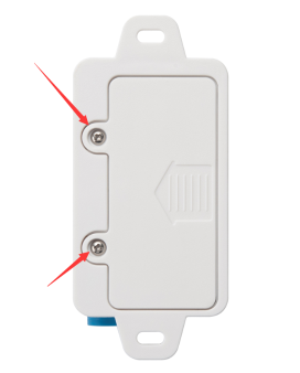
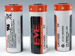
LHT65N has two screws on the back, Unscrew them, and changing the battery inside is ok. The battery is a general CR17450 battery. Any brand should be ok.
5.3 Battery Life Analyze
Dragino battery-powered products are all run in Low Power mode. User can check the guideline from this link to calculate the estimated battery life:
https://www.dragino.com/downloads/downloads/LoRa_End_Node/Battery_Analyze/DRAGINO_Battery_Life_Guide.pdf
A full detail test report for LHT65N on different frequency can be found at : https://www.dropbox.com/sh/r2i3zlhsyrpavla/AAB1sZw3mdT0K7XjpHCITt13a?dl=0
6. FAQ
6.1 How to connect to LHT65N UART interface?
The LHT65N has the UART interface in its Type-C. The UART Interface can be used for
- Send AT Commands, and get output from LHT65N
- Upgrade firmwre of LHT65N.
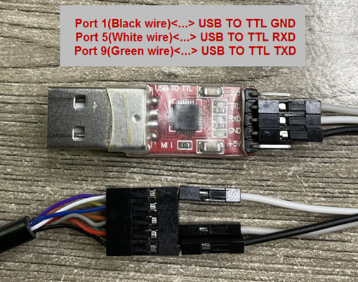
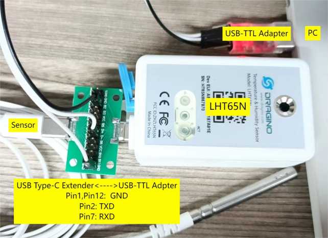
The hardware connection is: PC <--> USB to TTL Adapter <--> Jump wires <--> Type-C Adapter <--> LHT65N
Option of USB TTL adapter:
- CP2101 USB TTL Adapter
- CH340 USB TTL Adapter
- FT232 USB TTL Adapter
Option of Type-C Adapter:
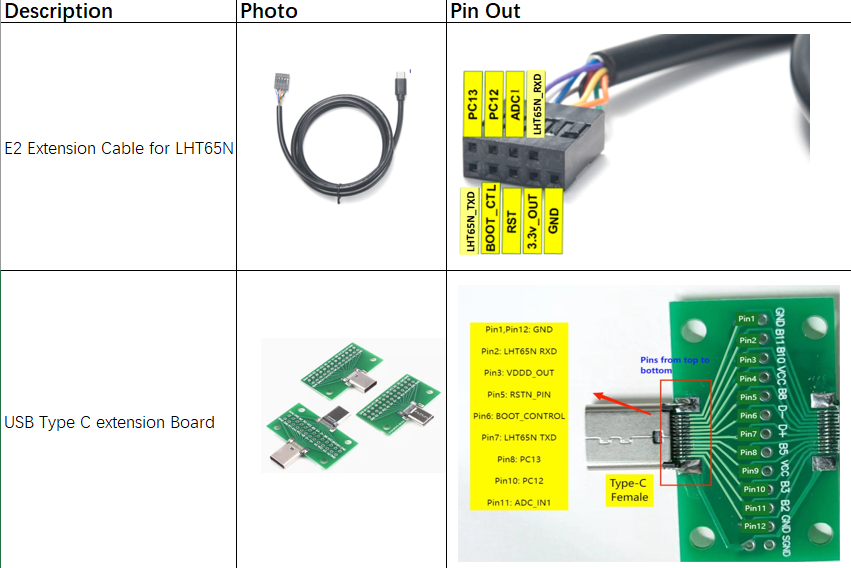
Connection:
- USB to TTL GND <--> LHT65N GND
- USB to TTL RXD <--> LHT65N TXD
- USB to TTL TXD <--> LHT65N RXD
Connection Example:
6.2 How to use AT Commands?
First, Connect PC and LHT65N via USB TTL adapter as FAQ 6.1
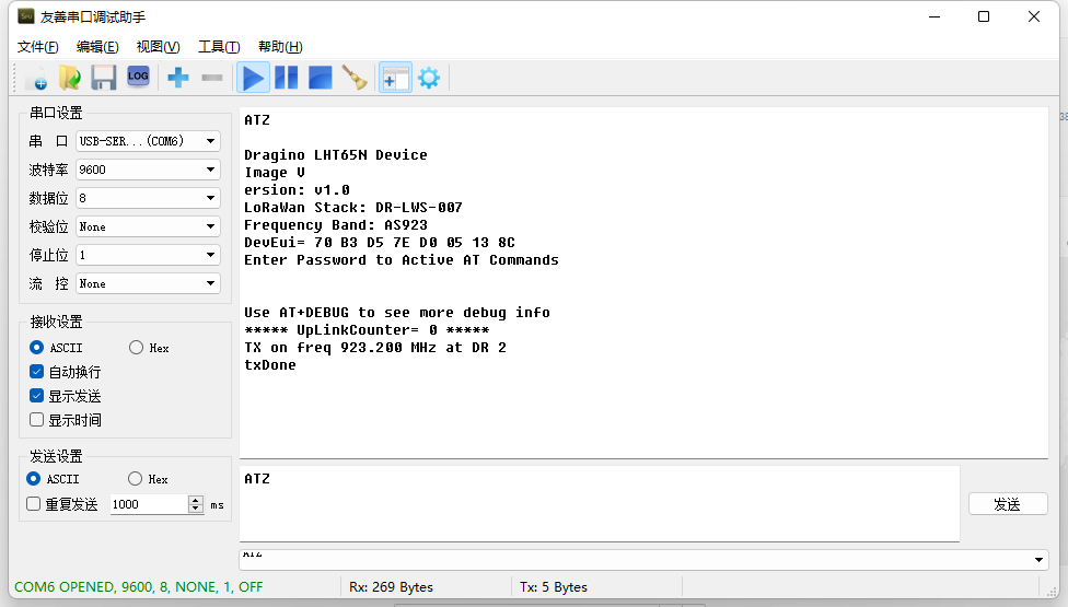
In PC, User needs to set serial tool(such as putty, SecureCRT) baud rate to 9600 to access to access serial console for LHT65N. The AT commands are disable by default and need to enter password (default:123456) to active it. Timeout to input AT Command is 5 min, after 5-minute, user need to input password again. User can use AT+DISAT command to disable AT command before timeout.
Input password and ATZ to activate LHT65N,As shown below:
AT Command List is as below:
AT+<CMD>? : Help on <CMD>
AT+<CMD> : Run <CMD>
AT+<CMD>=<value> : Set the value
AT+<CMD>=? : Get the value
AT+DEBUG: Set more info output
ATZ: Trig a reset of the MCU
AT+FDR: Reset Parameters to Factory Default, Keys Reserve
AT+DEUI: Get or Set the Device EUI
AT+DADDR: Get or Set the Device Address
AT+APPKEY: Get or Set the Application Key
AT+NWKSKEY: Get or Set the Network Session Key
AT+APPSKEY: Get or Set the Application Session Key
AT+APPEUI: Get or Set the Application EUI
AT+ADR: Get or Set the Adaptive Data Rate setting. (0: off, 1: on)
AT+TXP: Get or Set the Transmit Power (0-5, MAX:0, MIN:5, according to LoRaWAN Spec)
AT+DR: Get or Set the Data Rate. (0-7 corresponding to DR_X)
AT+DCS: Get or Set the ETSI Duty Cycle setting - 0=disable, 1=enable - Only for testing
AT+PNM: Get or Set the public network mode. (0: off, 1: on)
AT+RX2FQ: Get or Set the Rx2 window frequency
AT+RX2DR: Get or Set the Rx2 window data rate (0-7 corresponding to DR_X)
AT+RX1DL: Get or Set the delay between the end of the Tx and the Rx Window 1 in ms
AT+RX2DL: Get or Set the delay between the end of the Tx and the Rx Window 2 in ms
AT+JN1DL: Get or Set the Join Accept Delay between the end of the Tx and the Join Rx Window 1 in ms
AT+JN2DL: Get or Set the Join Accept Delay between the end of the Tx and the Join Rx Window 2 in ms
AT+NJM: Get or Set the Network Join Mode. (0: ABP, 1: OTAA)
AT+NWKID: Get or Set the Network ID
AT+FCU: Get or Set the Frame Counter Uplink
AT+FCD: Get or Set the Frame Counter Downlink
AT+CLASS: Get or Set the Device Class
AT+JOIN: Join network
AT+NJS: Get the join status
AT+SENDB: Send hexadecimal data along with the application port
AT+SEND: Send text data along with the application port
AT+RECVB: Print last received data in binary format (with hexadecimal values)
AT+RECV: Print last received data in raw format
AT+VER: Get current image version and Frequency Band
AT+CFM: Get or Set the confirmation mode (0-1)
AT+CFS: Get confirmation status of the last AT+SEND (0-1)
AT+SNR: Get the SNR of the last received packet
AT+RSSI: Get the RSSI of the last received packet
AT+TDC: Get or set the application data transmission interval in ms
AT+PORT: Get or set the application port
AT+DISAT: Disable AT commands
AT+PWORD: Set password, max 9 digits
AT+CHS: Get or Set Frequency (Unit: Hz) for Single Channel Mode
AT+CHE: Get or Set eight channels mode,Only for US915,AU915,CN470
AT+PDTA: Print the sector data from start page to stop page
AT+PLDTA: Print the last few sets of data
AT+CLRDTA: Clear the storage, record position back to 1st
AT+SLEEP: Set sleep mode
AT+EXT: Get or Set external sensor model
AT+BAT: Get the current battery voltage in mV
AT+CFG: Print all configurations
AT+WMOD: Get or Set Work Mode
AT+ARTEMP: Get or set the internal Temperature sensor alarm range
AT+CITEMP: Get or set the internal Temperature sensor collection interval in min
AT+SETCNT: Set the count at present
AT+RJTDC: Get or set the ReJoin data transmission interval in min
AT+RPL: Get or set response level
AT+TIMESTAMP: Get or Set UNIX timestamp in second
AT+LEAPSEC: Get or Set Leap Second
AT+SYNCMOD: Get or Set time synchronization method
AT+SYNCTDC: Get or set time synchronization interval in day
AT+PID: Get or set the PID
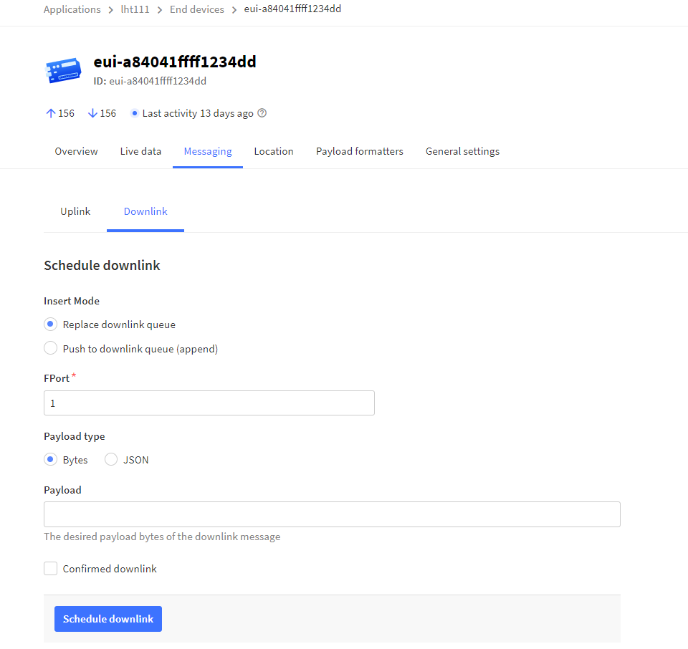
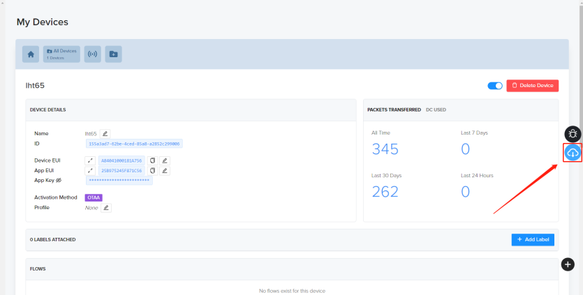
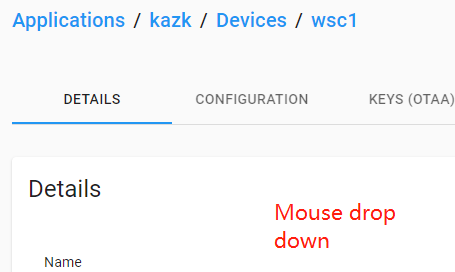
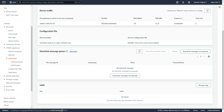
6.3 How to use Downlink commands?
Downlink commands:
TTN:
Helium:
Chirpstack: The downlink window will not be displayed until the network is accessed

AWS-IOT :
6.4 How to change the uplink interval?
Please see this link: http://wiki.dragino.com/xwiki/bin/view/Main/How%20to%20set%20the%20transmit%20time%20interval/
6.5 How to upgrade firmware?
The firmware before V1.4 does not have wireless upgrade function, and the starting address of the firmware is 0x08000000.
Since and including V1.4, LHT65N supports wireless upgrade, and its firmware is divided into bootloader + working firmware. Burning bootloader selects address 0x08000000, and burning working firmware selects address 0x0800D000.
LHT65N has two types of firmware: Firmware with bootloader and Firmware without bootloader. Firmware Download Link:
Use UART connection to update the firmware, detailed description of UART refer to FAQ 6.1, Connection Example:


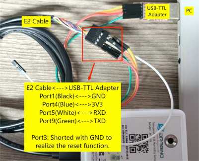
Note: To use the TremoProgrammer the node must be put into burn mode, i.e. the USB-TTL adapter 3.3V must be connected to the BOOT_CONTROL pin of the LHT65N.
- For the connection E2 cable <----> USB-TTL adapter:
Port 4(Blue wire)<---->USB-TTL 3V3

- For the connection USB Type-C Extender<---->USB-TTL adapter:
Pin 6<---->USB-TTL 3V3

6.5.1 Burning firmware before V1.3 (including V1.3)
Burning firmware prior to and including V1.3 can only be done using the TremoProgrammer, select the burn address: 0x08000000
According to the above instructions to enter the burning mode, re-install the battery to reset the node, press the ACT button LED does not light up, the node successfully entered the burning mode, click "START".

6.5.2 Updated firmware for V1.4 and above
Updating firmware version V1.4 and above requires distinguishing whether the firmware comes with a bootloader or not.
- For version V1.4 and above, we ship nodes with bootloader, users can directly choose firmware without bootloader to upgrade directly. Use TremoProgrammer to start at address 0x0800D000. Using Dragino Sensor Manager Utility.exe does not require address selection, but must use firmware without bootloader.
- For nodes where the bootloader was accidentally erased, customers need to burn the bootloader and working firmware using TremoProgrammer.
The firmware of V1.4 and above updated on our official website will note whether it comes with bootloader or not, customers need to choose the appropriate update method according to the firmware type.
6.5.2.1 Update firmware (Assume device already have bootloader)
Step1 : Connect UART as per FAQ 6.1
Step2 : Update follow Instruction for update via DraginoSensorManagerUtility.exe. Make sure to use the firmware without bootloader.
(Recommanded way) OTA firmware update via wireless : http://wiki.dragino.com/xwiki/bin/view/Main/Firmware%20OTA%20Update%20for%20Sensors/
6.5.2.2 Update firmware (Assume device doesn't have bootloader)
In this update method, make sure to use the firmware with bootloader , Download Link . After update , device will have bootloader so can use above method( 6.5.2.1) to update.
Step1: Install TremoProgrammer first.

Step2: Hardware Connection
Connect PC and LHT65N via USB TTL adapter .
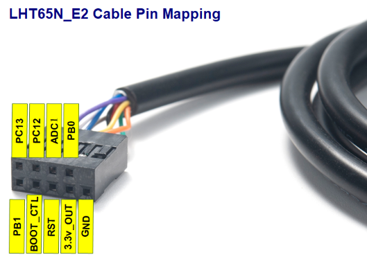
Note: Burn mode: Port4 (BOOT_CTL) of E2 cable connects 3V3 of USB-TTL.
Connection method:
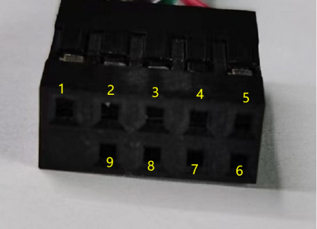
USB-TTL GND <--> Port 1 of E2 cable
USB-TTL 3V3 <--> Port 4 of E2 cable
USB-TTL TXD <--> Port 9 of E2 cable
USB-TTL RXD <--> Port 5 of E2 cable
Step3: Select the device port to be connected, baud rate and bin file to be downloaded.
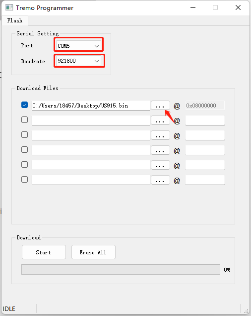
Reset node: Short-circuit the port3(RST) of the E2 cable to GND. /The new motherboard cancels the RST, and the battery needs to be reinstalled to achieve the reset effect.
Then click the start button to start the firmware upgrade.
When this interface appears, it indicates that the download has been completed.
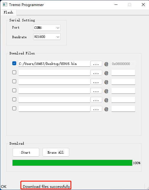
Finally, Disconnect Port4 of E2 cable, reset the node again (Port3 shorted GND/ /The new motherboard cancels the RST, and the battery needs to be reinstalled to achieve the reset effect.), and the node exits burning mode.
6.6 Why can't I see the datalog information
1. The time is not aligned, and the correct query command is not used.
2. Decoder error, did not parse the datalog data, the data was filtered.
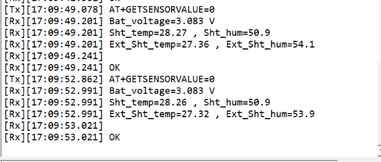
6.7 How can i read sensor data without LoRaWAN? For Calibration Purpose
Some clients need to calibrate the sensor value in calibration Lab. In such case, Reading the data without LoRaWAN network is more convinient. To achieve this, use can use a USB Type-C Breakout board to expose the UART pins while still have the probe connected. See below. Detail Pin out please refer the FAQ of how to connect UART
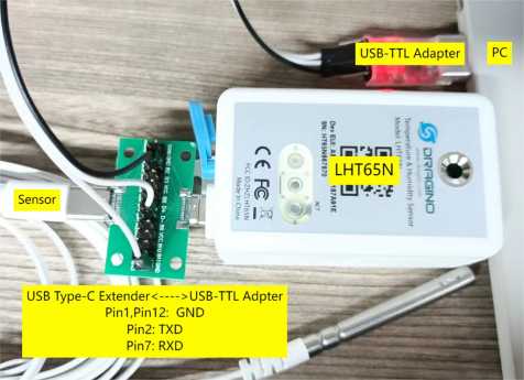
After there is UART Connectio, run below commands:
1. AT+NJM=0 // Set Device to ABP mode , so can works without join to LoRaWAN server.
2. AT+GETSENSORVALUE=0 //The serial port gets the reading of the current sensor.
Example output:
7. Order Info
Part Number: LHT65N-XX-YY
XX : The default frequency band
- AS923: LoRaWAN AS923 band
- AU915: LoRaWAN AU915 band
- EU433: LoRaWAN EU433 band
- EU868: LoRaWAN EU868 band
- KR920: LoRaWAN KR920 band
- US915: LoRaWAN US915 band
- IN865: LoRaWAN IN865 band
- CN470: LoRaWAN CN470 band
YY: Sensor Accessories
- E3: External Temperature Probe
8. Packing Info
Package Includes:
- LHT65N Temperature & Humidity Sensor x 1
- Optional external sensor
9. Reference material
10. FCC Warning
This device complies with part 15 of the FCC Rules.Operation is subject to the following two conditions:
(1) This device may not cause harmful interference;
(2) this device must accept any interference received, including interference that may cause undesired operation.
