

Table of Contents:


1. Introduction
1.1 What is LoRaWAN Pressure Sensor
The Dragino PS-LB series sensors are LoRaWAN Pressure Sensor for Internet of Things solution. PS-LB can measure Air, Water pressure and liquid level and upload the sensor data via wireless to LoRaWAN IoT server.
The PS-LB series sensors include Thread Installation Type and Immersion Type, it supports different pressure range which can be used for different measurement requirement.
The LoRa wireless technology used in PS-LB allows device to send data and reach extremely long ranges at low data-rates. It provides ultra-long range spread spectrum communication and high interference immunity whilst minimizing current consumption.
PS-LB supports BLE configure and wireless OTA update which make user easy to use.
PS-LB is powered by 8500mAh Li-SOCI2 battery, it is designed for long term use up to 5 years.
Each PS-LB is pre-load with a set of unique keys for LoRaWAN registrations, register these keys to local LoRaWAN server and it will auto connect after power on.
1.2 Features
- LoRaWAN 1.0.3 Class A
- Ultra-low power consumption
- Measure air / gas or water pressure
- Different pressure range available
- Thread Installation Type or Immersion Type
- Monitor Battery Level
- Bands: CN470/EU433/KR920/US915/EU868/AS923/AU915/IN865
- Support Bluetooth v5.1 and LoRaWAN remote configure
- Support wireless OTA update firmware
- Uplink on periodically
- Downlink to change configure
- 8500mAh Battery for long term use
1.3 Specification
Micro Controller:
- MCU: 48Mhz ARM
- Flash: 256KB
- RAM: 64KB
Common DC Characteristics:
- Supply Voltage: 2.5v ~ 3.6v
- Operating Temperature: -40 ~ 85°C
LoRa Spec:
- Frequency Range, Band 1 (HF): 862 ~ 1020 Mhz
- Max +22 dBm constant RF output vs.
- RX sensitivity: down to -139 dBm.
- Excellent blocking immunity
Current Input Measuring :
- Range: 0 ~ 20mA
- Accuracy: 0.02mA
- Resolution: 0.001mA
Voltage Input Measuring:
- Range: 0 ~ 30v
- Accuracy: 0.02v
- Resolution: 0.001v
Battery:
- Li/SOCI2 un-chargeable battery
- Capacity: 8500mAh
- Self-Discharge: <1% / Year @ 25°C
- Max continuously current: 130mA
- Max boost current: 2A, 1 second
Power Consumption
- Sleep Mode: 5uA @ 3.3v
- LoRa Transmit Mode: 125mA @ 20dBm, 82mA @ 14dBm
1.4 Probe Types
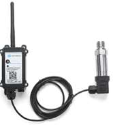
1.4.1 Thread Installation Type
- Hersman Pressure Transmitter
- Measuring Range: -0.1 ~ 0 ~ 60MPa, see order info.
- Accuracy: 0.2% F.S
- Long-Term Stability: 0.2% F.S ±0.05%
- Overload 200% F.S
- Zero Temperature Drift: 0.03% FS/℃(≤100Kpa), 0.02%FS/℃(>100Kpa)
- FS Temperature Drift: 0.003% FS/℃(≤100Kpa), 0.002%FS/℃(>100Kpa)
- Storage temperature: -30℃~80℃
- Operating temperature: -20℃~60℃
- Connector Type: Various Types, see order info
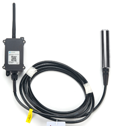
1.4.2 Immersion Type
- Immersion Type, Probe IP Level: IP68
- Measuring Range: Measure range can be customized, up to 100m.
- Accuracy: 0.2% F.S
- Long-Term Stability: ±0.2% F.S / Year
- Overload 200% F.S
- Zero Temperature Drift: ±2% F.S)
- FS Temperature Drift: ±2% F.S
- Storage temperature: -30℃~80℃
- Operating temperature: -40℃~85℃
- Material: 316 stainless steels
-
- Probe Dimension
-
- Application and Installation
- Thread Installation Type
- Application and Installation
Application:
- Hydraulic Pressure
- Petrochemical Industry
- Health and Medical
- Food & Beverage Processing
- Auto-controlling house
- Constant Pressure Water Supply
- Liquid Pressure measuring
Order the suitable thread size and install to measure the air / liquid pressure

-
-
- Immersion Type
-
Application:
Liquid & Water Pressure / Level detect.

The Immersion Type pressure sensor is shipped with the probe and device separately. When user got the device, below is the wiring to for connect the probe to the device.


-
- Sleep mode and working mode
Deep Sleep Mode: Sensor doesn’t have any LoRaWAN activate. This mode is used for storage and shipping to save battery life.
Working Mode: In this mode, Sensor will work as LoRaWAN Sensor to Join LoRaWAN network and send out sensor data to server. Between each sampling/tx/rx periodically, sensor will be in IDLE mode), in IDLE mode, sensor has the same power consumption as Deep Sleep mode.
-
- Button & LEDs

| Behavior on ACT | Function | Action |
| Pressing ACT between 1s < time < 3s | Send an uplink | If sensor is already Joined to LoRaWAN network, sensor will send an uplink packet, blue led will blink once. Meanwhile, BLE module will be active and user can connect via BLE to configure device. |
| Pressing ACT for more than 3s | Active Device | Green led will fast blink 5 times, device will enter OTA mode for 3 seconds. And then start to JOIN LoRaWAN network. Green led will solidly turn on for 5 seconds after joined in network. Once sensor is active, BLE module will be active and user can connect via BLE to configure device, no matter if device join or not join LoRaWAN network. |
| Fast press ACT 5 times. | Deactivate Device | red led will solid on for 5 seconds. Means PS-LB is in Deep Sleep Mode. |
-
- Pin Mapping

-
- BLE connection
PS-LB support BLE remote configure.
BLE can be used to configure the parameter of sensor or see the console output from sensor. BLE will be only activate on below case:
- Press button to send an uplink
- Press button to active device.
- Device Power on or reset.
If there is no activity connection on BLE in 60 seconds, sensor will shut down BLE module to enter low power mode.
-
- Mechanical


- Configure PS-LB to connect to LoRaWAN network
- How it works
The PS-LB is configured as LoRaWAN OTAA Class A mode by default. It has OTAA keys to join LoRaWAN network. To connect a local LoRaWAN network, you need to input the OTAA keys in the LoRaWAN IoT server and activate the PS-LB. It will automatically join the network via OTAA and start to send the sensor value. The default uplink interval is 20 minutes.
-
- Quick guide to connect to LoRaWAN server (OTAA)
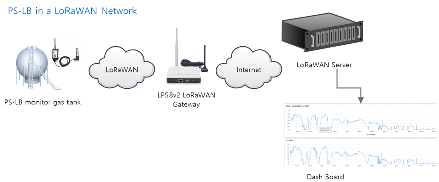
Following is an example for how to join the TTN v3 LoRaWAN Network. Below is the network structure; we use the LPS8v2 as a LoRaWAN gateway in this example.

The LPS8V2 is already set to connected to TTN network , so what we need to now is configure the TTN server.
Step 1: Create a device in TTN with the OTAA keys from PS-LB.
Each PS-LB is shipped with a sticker with the default device EUI as below:

You can enter this key in the LoRaWAN Server portal. Below is TTN screen shot:
Register the device

Add APP EUI and DEV EUI

Add APP EUI in the application

Add APP KEY

Step 2: Activate on PS-LB
Press the button for 5 seconds to activate the PS-LB.
Green led will fast blink 5 times, device will enter OTA mode for 3 seconds. And then start to JOIN LoRaWAN network. Green led will solidly turn on for 5 seconds after joined in network.
After join success, it will start to upload messages to TTN and you can see the messages in the panel.

-
- Uplink Payload
Uplink payloads have two types:
- Distance Value: Use FPORT=2
- Other control commands: Use other FPORT fields.
The application server should parse the correct value based on FPORT settings.
-
-
- Device Status, FPORT=5
-
Include device configure status. Once PS-LB Joined the network, it will uplink this message to the server.
Users can also use the downlink command(0x26 01) to ask PS-LB to resend this uplink.
| Device Status (FPORT=5) | |||||
| Size (bytes) | 1 | 2 | 1 | 1 | 2 |
| Value | Sensor Model | Firmware Version | Frequency Band | Sub-band | BAT |
Example parse in TTNv3

Sensor Model: For PS-LB, this value is 0x16
Firmware Version: 0x0100, Means: v1.0.0 version
Frequency Band:
*0x01: EU868
*0x02: US915
*0x03: IN865
*0x04: AU915
*0x05: KZ865
*0x06: RU864
*0x07: AS923
*0x08: AS923-1
*0x09: AS923-2
*0x0a: AS923-3
*0x0b: CN470
*0x0c: EU433
*0x0d: KR920
*0x0e: MA869
Sub-Band:
AU915 and US915:value 0x00 ~ 0x08
CN470: value 0x0B ~ 0x0C
Other Bands: Always 0x00
Battery Info:
Check the battery voltage.
Ex1: 0x0B45 = 2885mV
Ex2: 0x0B49 = 2889mV
-
-
- Sensor value, FPORT=2
-
Uplink payload includes in total 9 bytes.
Size (bytes) | 2 | 2 | 2 | 2 | 1 |
| Value | BAT | Probe Model | 0 ~ 20mA value | 0 ~ 30v value | IN1 &IN2 Interrupt flag |
-
-
- Battery Info
-
Check the battery voltage for PS-LB.
Ex1: 0x0B45 = 2885mV
Ex2: 0x0B49 = 2889mV
-
-
- Probe Model
-
PS-LB has different kind of probe, 0~20mA represent the full scale of the measuring range. So a 15mA output means different meaning for different probe.
For example.
| Part Number | Probe Used | 0~20mA scale | Example: 10mA meaning |
| PS-LB-I3 | immersion type with 3 meters cable | 0~3 meters | 1.5 meters pure water |
| PS-LB-I5 | immersion type with 5 meters cable | 0~5 meters | 2.5 meters pure water |
The probe model field provides the convenient for server to identical how it should parse the 0~20mA sensor value and get the correct value.
-
-
- 0~20mA value (IDC_IN)
-
The output value from Pressure Probe, use together with Probe Model to get the pressure value or water level.
Example:
27AE(H) = 10158 (D)/1000 = 10.158mA.
-
-
- 0~30V value ( pin VDC_IN)
-
Measure the voltage value. The range is 0 to 30V.
Example:
138E(H) = 5006(D)/1000= 5.006V
-
-
- IN1&IN2&INT pin
-
IN1 and IN2 are used as digital input pins.
Example:
09 (H) ![]() 0x09&0x08)>>3=1 IN1 pin is high level.
0x09&0x08)>>3=1 IN1 pin is high level.
09 (H) ![]() 0x09&0x04)>>2=0 IN2 pin is low level.
0x09&0x04)>>2=0 IN2 pin is low level.
This data field shows if this packet is generated by Interrupt Pin or not. Click here for the hardware and software set up. Note: The Internet Pin is a separate pin in the screw terminal.
Example:
09 (H) : (0x09&0x02)>>1=1 The level of the interrupt pin.
09 (H) : 0x09&0x01=1 0x00: Normal uplink packet.
0x01: Interrupt Uplink Packet.
-
-
- Decode payload in The Things Network
-
While using TTN network, you can add the payload format to decode the payload.

PS-LB TTN Payload Decoder:
https://github.com/dragino/dragino-end-node-decoder
-
- Uplink Interval
The PS-LB by default uplink the sensor data every 20 minutes. User can change this interval by AT Command or LoRaWAN Downlink Command. See this link:
-
- Show Data in DataCake IoT Server
DATACAKE provides a human friendly interface to show the sensor data, once we have data in TTN, we can use DATACAKE to connect to TTN and see the data in DATACAKE. Below are the steps:
Step 1: Be sure that your device is programmed and properly connected to the network at this time.
Step 2: To configure the Application to forward data to DATACAKE you will need to add integration. To add the DATACAKE integration, perform the following steps:


Step 3: Create an account or log in Datacake.
Step 4: Create PS-LB product.


Step 5: add payload decode


After added, the sensor data arrive TTN, it will also arrive and show in Datacake.

-
- Frequency Plans
The PS-LB uses OTAA mode and below frequency plans by default. If user want to use it with different frequency plan, please refer the AT command sets.
https://wiki.dragino.com/index.php?title=End_Device_Frequency_Band
-
- Firmware Change Log
Firmware download link:
https://www.dropbox.com/sh/gf1glloczbzz19h/AABbuYI4WY6VdAmpXo6o1V2Ka?dl=0
- Configure PS-LB via AT Command or LoRaWAN Downlink
Use can configure PS-LB via AT Command or LoRaWAN Downlink.
- AT Command Connection: See FAQ.
- LoRaWAN Downlink instruction for different platforms:
http://wiki.dragino.com/index.php?title=Main_Page#Use_Note_for_Server
There are two kinds of commands to configure PS-LB, they are:
- General Commands.
These commands are to configure:
- General system settings like: uplink interval.
- LoRaWAN protocol & radio related command.
They are same for all Dragino Device which support DLWS-005 LoRaWAN Stack. These commands can be found on the wiki:
http://wiki.dragino.com/index.php?title=End_Device_Downlink_Command
- Commands special design for PS-LB
These commands only valid for PS-LB, as below:
-
- Set Transmit Interval Time
Feature: Change LoRaWAN End Node Transmit Interval.
AT Command: AT+TDC
| Command Example | Function | Response |
| AT+TDC=? | Show current transmit Interval | 30000 OK the interval is 30000ms = 30s |
| AT+TDC=60000 | Set Transmit Interval | OK Set transmit interval to 60000ms = 60 seconds |
Downlink Command: 0x01
Format: Command Code (0x01) followed by 3 bytes time value.
If the downlink payload=0100003C, it means set the END Node’s Transmit Interval to 0x00003C=60(S), while type code is 01.
- Example 1: Downlink Payload: 0100001E // Set Transmit Interval (TDC) = 30 seconds
- Example 2: Downlink Payload: 0100003C // Set Transmit Interval (TDC) = 60 seconds
-
- Set Interrupt Mode
Feature, Set Interrupt mode for GPIO_EXIT.
AT Command: AT+INTMOD
| Command Example | Function | Response |
| AT+INTMOD=? | Show current interrupt mode | 0 OK the mode is 0 = No interruption |
| AT+INTMOD=2 | Set Transmit Interval
| OK |
Downlink Command: 0x06
Format: Command Code (0x06) followed by 3 bytes.
This means that the interrupt mode of the end node is set to 0x000003=3 (rising edge trigger), and the type code is 06.
- Example 1: Downlink Payload: 06000000 // Turn off interrupt mode
- Example 2: Downlink Payload: 06000003 // Set the interrupt mode to rising edge trigger
-
- Set the output time
Feature, Control the output 3V3 , 5V or 12V.
AT Command: AT+3V3T
| Command Example | Function | Response |
| AT+3V3T=? | Show 3V3 open time. | 0 OK |
| AT+3V3T=0 | Normally open 3V3 power supply. | OK default setting |
| AT+3V3T=1000 | Close after a delay of 1000 milliseconds. | OK
|
| AT+3V3T=65535 | Normally closed 3V3 power supply. | OK
|
AT Command: AT+5VT
| Command Example | Function | Response |
| AT+5VT=? | Show 5V open time. | 0 OK |
| AT+5VT=0 | Normally closed 5V power supply. | OK default setting |
| AT+5VT=1000 | Close after a delay of 1000 milliseconds. | OK
|
| AT+5VT=65535 | Normally open 5V power supply. | OK
|
AT Command: AT+12VT
| Command Example | Function | Response |
| AT+12VT=? | Show 12V open time. | 0 OK |
| AT+12VT=0 | Normally closed 12V power supply. | OK |
| AT+12VT=500 | Close after a delay of 500 milliseconds. | OK
|
Downlink Command: 0x07
Format: Command Code (0x07) followed by 3 bytes.
The first byte is which power, the second and third bytes are the time to turn on.
- Example 1: Downlink Payload: 070101F4 -> AT+3V3T=500
- Example 2: Downlink Payload: 0701FFFF -> AT+3V3T=65535
- Example 3: Downlink Payload: 070203E8 -> AT+5VT=1000
- Example 4: Downlink Payload: 07020000 -> AT+5VT=0
- Example 5: Downlink Payload: 070301F4 -> AT+12VT=500
- Example 6: Downlink Payload: 07030000 -> AT+12VT=0
-
- Set the Probe Model
AT Command: AT +PROBE
| Command Example | Function | Response |
| AT +PROBE =? | Get or Set the probe model. | 0 OK |
| AT +PROBE =0003 | Set water depth sensor mode, 3m type. | OK |
| AT +PROBE =0101 | Set pressure transmitters mode, first type. | OK
|
| AT +PROBE =0000 | Initial state, no settings. | OK
|
Downlink Command: 0x08
Format: Command Code (0x08) followed by 2 bytes.
- Example 1: Downlink Payload: 080003 -> AT+PROBE=0003
- Example 2: Downlink Payload: 080101 -> AT+PROBE=0101
- Battery & how to replace
- Battery Type
PS-LB is equipped with a 8500mAH ER26500 Li-SOCI2 battery. The battery is un-rechargeable battery with low discharge rate targeting for 8~10 years use. This type of battery is commonly used in IoT target for long-term running, such as water meter.
The discharge curve is not linear so can’t simply use percentage to show the battery level. Below is the battery performance.

Minimum Working Voltage for the PS-LB:
PS-LB: 2.45v ~ 3.6v
-
- Replace Battery
Any battery with range 2.45 ~ 3.6v can be a replacement. We recommend to use Li-SOCl2 Battery.
And make sure the positive and negative pins match.
-
- Power Consumption Analyze
Dragino Battery powered product are all runs in Low Power mode. We have an update battery calculator which base on the measurement of the real device. User can use this calculator to check the battery life and calculate the battery life if want to use different transmit interval.
Instruction to use as below:
Step 1: Downlink the up-to-date DRAGINO_Battery_Life_Prediction_Table.xlsx from:
https://www.dragino.com/downloads/index.php?dir=LoRa_End_Node/Battery_Analyze/
Step 2: Open it and choose
- Product Model
- Uplink Interval
- Working Mode
And the Life expectation in difference case will be shown on the right.

The battery related documents as below:
- Battery Dimension,
- Lithium-Thionyl Chloride Battery datasheet, Tech Spec
- Lithium-ion Battery-Capacitor datasheet, Tech Spec
JST-XH-2P connector |

-
-
- Battery Note
-
The Li-SICO battery is designed for small current / long period application. It is not good to use a high current, short period transmit method. The recommended minimum period for use of this battery is 5 minutes. If you use a shorter period time to transmit LoRa, then the battery life may be decreased.
-
-
- Replace the battery
-
You can change the battery in the PS-LB.The type of battery is not limited as long as the output is between 3v to 3.6v. On the main board, there is a diode (D1) between the battery and the main circuit. If you need to use a battery with less than 3.3v, please remove the D1 and shortcut the two pads of it so there won’t be voltage drop between battery and main board.
The default battery pack of PS-LB includes a ER26500 plus super capacitor. If user can’t find this pack locally, they can find ER26500 or equivalence, which will also work in most case. The SPC can enlarge the battery life for high frequency use (update period below 5 minutes)
- Remote Configure device
- Connect via BLE
Please see this instruction for how to configure via BLE:
http://wiki.dragino.com/xwiki/bin/view/Main/BLE%20Bluetooth%20Remote%20Configure/
-
- AT Command Set
- OTA firmware update
Please see this link for how to do OTA firmware update.
http://wiki.dragino.com/xwiki/bin/view/Main/Firmware%20OTA%20Update%20for%20Sensors/
- FAQ
- How to use AT Command to access device?
-
- How to update firmware via UART port?
See:
-
- How to change the LoRa Frequency Bands/Region
You can follow the instructions for how to upgrade image.
When downloading the images, choose the required image file for download.
- Order Info

- Packing Info
Package Includes:
- PS-LB LoRaWAN Pressure Sensor
Dimension and weight:
- Device Size: cm
- Device Weight: g
- Package Size / pcs : cm
- Weight / pcs : g
- Support
- Support is provided Monday to Friday, from 09:00 to 18:00 GMT+8. Due to different timezones we cannot offer live support. However, your questions will be answered as soon as possible in the before-mentioned schedule.
- Provide as much information as possible regarding your enquiry (product models, accurately describe your problem and steps to replicate it etc) and send a mail to