D20-LB/D22-LB/D23-LB LoRaWAN Temperature Sensor User Manual
Table of Contents:
- 1. Introduction
- 2. Configure D2x-LB to connect to LoRaWAN network
- 3. Configure D2x-LB
- 4. Battery & Power Consumption
- 5. OTA firmware update
- 6. FAQ
- 7. Order Info
- 8. Packing Info
- 9. Support
1. Introduction
1.1 What is D2x-LB LoRaWAN Temperature Sensor
The Dragino D2x-LB is a LoRaWAN Temperature Sensor for Internet of Things solution. D2x-LB has 5v and 12v output , 4~20mA, 0~30v input interface to power and get value from Analog Sensor. D2x-LB will convert the Analog Value to LoRaWAN wireless data and send to IoT platform via LoRaWAN gateway.
The LoRa wireless technology used in D2x-LB allows device to send data and reach extremely long ranges at low data-rates. It provides ultra-long range spread spectrum communication and high interference immunity whilst minimizing current consumption.
The temperature sensor used in D2x-LB can measure -55°C ~ 125°C with accuracy ±0.5°C (max ±2.0 °C).
D2x-LB supports temperature alarm feature, user can set temperature alarm for instant notice.
D2x-LB has max 3 probes which measure maximum 3 temperature points.
D2x-LB supports BLE configure and wireless OTA update which make user easy to use.
D2x-LB is powered by 8500mAh Li-SOCI2 battery, it is designed for long term use up to 5 years.
Each D2x-LB is pre-load with a set of unique keys for LoRaWAN registrations, register these keys to local LoRaWAN server and it will auto connect after power on.
1.2 Features
- LoRaWAN 1.0.3 Class A
- Ultra-low power consumption
- 1 ~ 3 External Temperature Probesr
- Measure range -55°C ~ 125°C
- Temperature alarm
- Bands: CN470/EU433/KR920/US915/EU868/AS923/AU915/IN865
- Support Bluetooth v5.1 and LoRaWAN remote configure
- Support wireless OTA update firmware
- Uplink on periodically
- Downlink to change configure
- 8500mAh Battery for long term use
1.3 Specification
Common DC Characteristics:
- Supply Voltage: built in 8500mAh Li-SOCI2 battery , 2.5v ~ 3.6v
- Operating Temperature: -40 ~ 85°C
Temperature Sensor:
- Dallas DS18B20
- Range: -55 to + 125°C
- Accuracy ±0.5°C (max ±2.0 °C).
LoRa Spec:
- Frequency Range, Band 1 (HF): 862 ~ 1020 Mhz
- Max +22 dBm constant RF output vs.
- RX sensitivity: down to -139 dBm.
- Excellent blocking immunity
Battery:
- Li/SOCI2 un-chargeable battery
- Capacity: 8500mAh
- Self-Discharge: <1% / Year @ 25°C
- Max continuously current: 130mA
- Max boost current: 2A, 1 second
Power Consumption
- Sleep Mode: 5uA @ 3.3v
- LoRa Transmit Mode: 125mA @ 20dBm, 82mA @ 14dBm
1.4 Sleep mode and working mode
Deep Sleep Mode: Sensor doesn't have any LoRaWAN activate. This mode is used for storage and shipping to save battery life.
Working Mode: In this mode, Sensor will work as LoRaWAN Sensor to Join LoRaWAN network and send out sensor data to server. Between each sampling/tx/rx periodically, sensor will be in IDLE mode), in IDLE mode, sensor has the same power consumption as Deep Sleep mode.
1.5 Button & LEDs
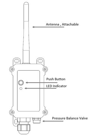
| Behavior on ACT | Function | Action |
|---|---|---|
| Pressing ACT between 1s < time < 3s | Send an uplink | If sensor is already Joined to LoRaWAN network, sensor will send an uplink packet, blue led will blink once. |
| Pressing ACT for more than 3s | Active Device | Green led will fast blink 5 times, device will enter OTA mode for 3 seconds. And then start to JOIN LoRaWAN network. |
| Fast press ACT 5 times. | Deactivate Device | Red led will solid on for 5 seconds. Means D2x-LB is in Deep Sleep Mode. |
1.6 BLE connection
D2x-LB support BLE remote configure.
BLE can be used to configure the parameter of sensor or see the console output from sensor. BLE will be only activate on below case:
- Press button to send an uplink
- Press button to active device.
- Device Power on or reset.
If there is no activity connection on BLE in 60 seconds, sensor will shut down BLE module to enter low power mode.
1.7 Hardware Variant
| Model | Photo | Probe Info |
|---|---|---|
| D20-LB | 1 x DS28B20 Probe Cable Length : 2 meters
| |
| D22-LB | ||
D23-LB |
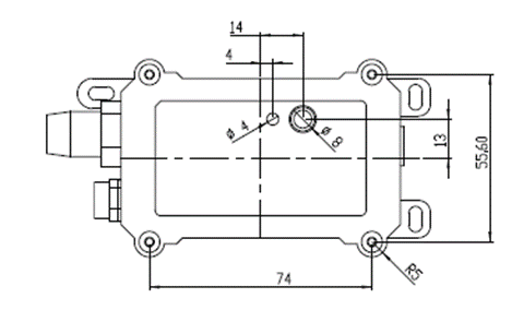
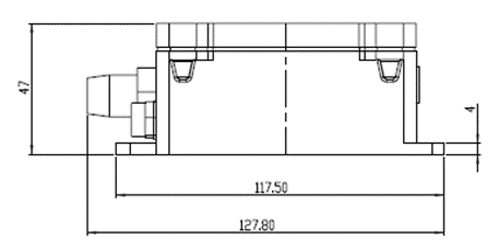
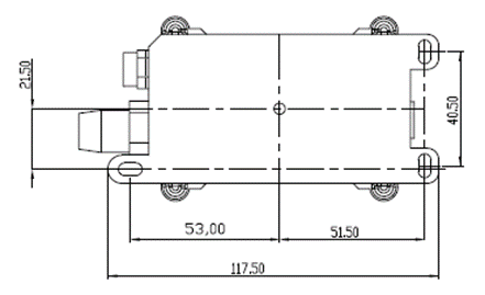
1.8 Mechanical
2. Configure D2x-LB to connect to LoRaWAN network
2.1 How it works
The D2x-LB is configured as LoRaWAN OTAA Class A mode by default. It has OTAA keys to join LoRaWAN network. To connect a local LoRaWAN network, you need to input the OTAA keys in the LoRaWAN IoT server and press the button to activate the D2x-LB. It will automatically join the network via OTAA and start to send the sensor value. The default uplink interval is 20 minutes.
2.2 Quick guide to connect to LoRaWAN server (OTAA)
Following is an example for how to join the TTN v3 LoRaWAN Network. Below is the network structure; we use the LPS8v2 as a LoRaWAN gateway in this example.
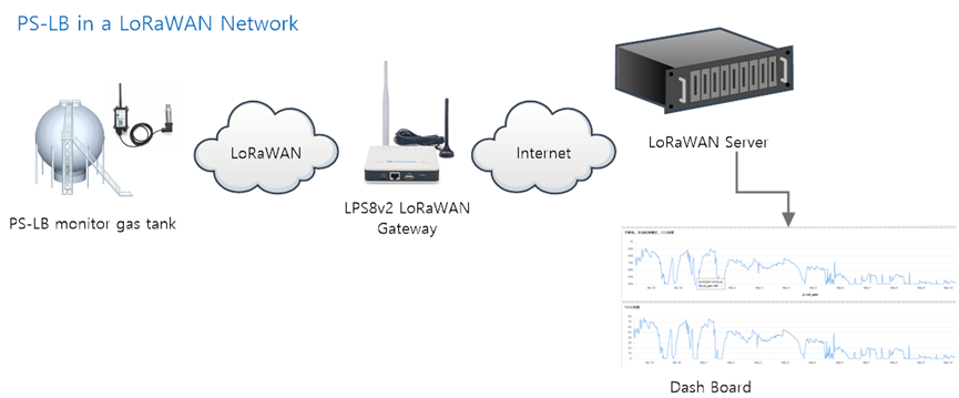
The LPS8V2 is already set to connected to TTN network , so what we need to now is configure the TTN server.
Step 1: Create a device in TTN with the OTAA keys from D2x-LB.
Each D2x-LB is shipped with a sticker with the default device EUI as below:
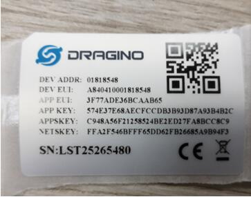
You can enter this key in the LoRaWAN Server portal. Below is TTN screen shot:
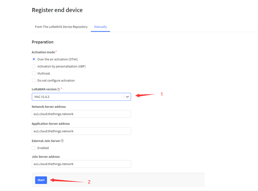
Register the device
Add APP EUI and DEV EUI
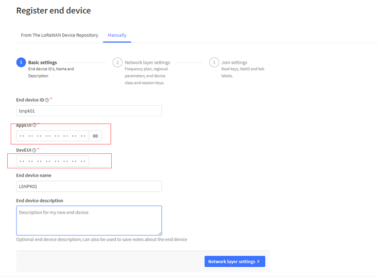
Add APP EUI in the application
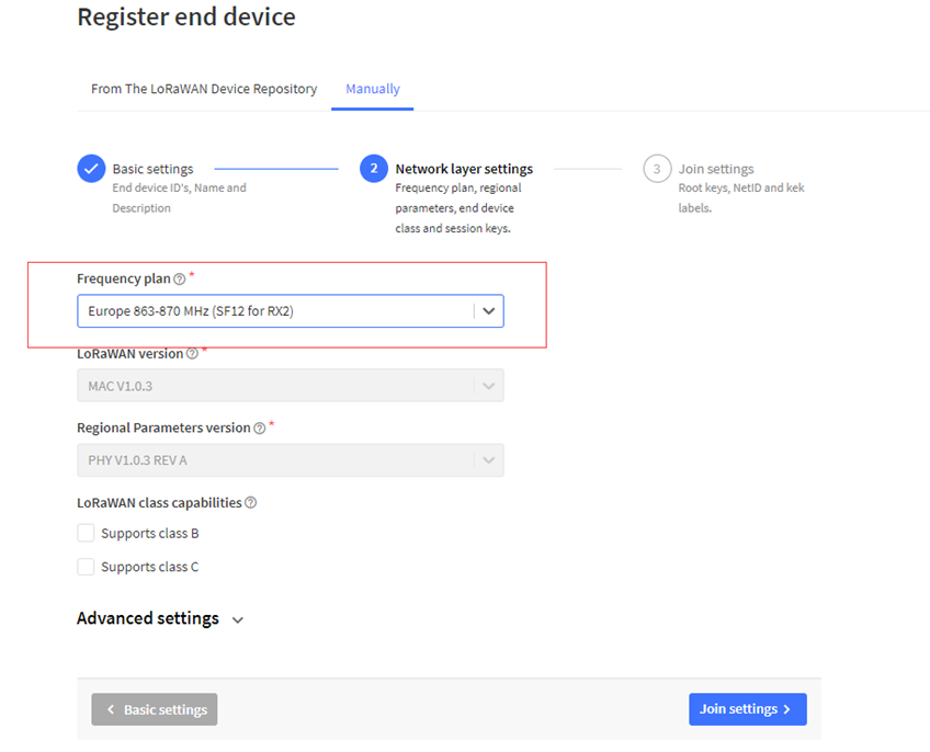
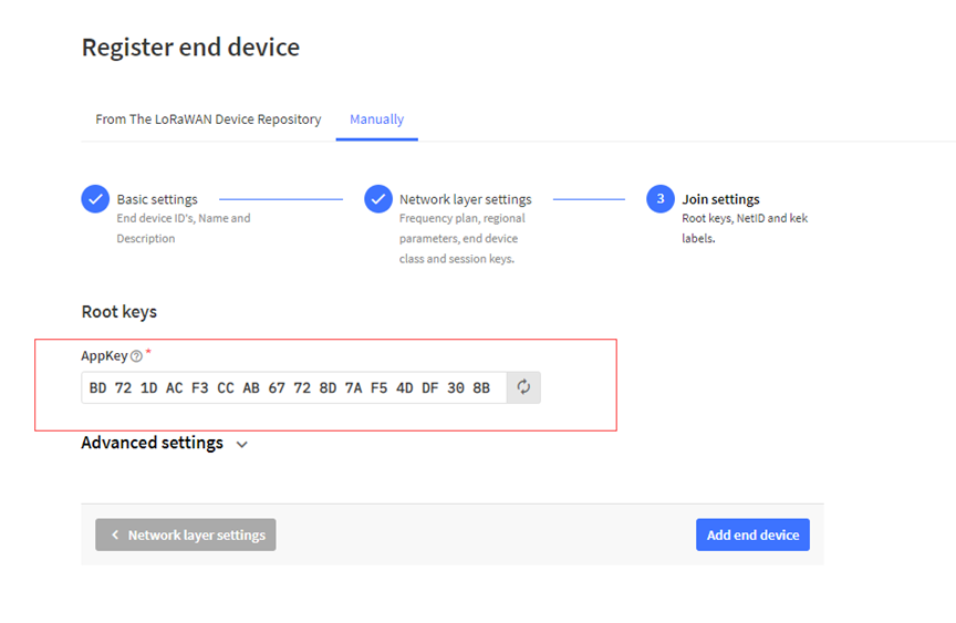
Add APP KEY
Step 2: Activate on D2x-LB
Press the button for 5 seconds to activate the D2x-LB.
Green led will fast blink 5 times, device will enter OTA mode for 3 seconds. And then start to JOIN LoRaWAN network. Green led will solidly turn on for 5 seconds after joined in network.
After join success, it will start to upload messages to TTN and you can see the messages in the panel.
2.3 Uplink Payload
2.3.1 Device Status, FPORT=5
Users can use the downlink command(0x26 01) to ask D2x-LB to send device configure detail, include device configure status. D2x-LB will uplink a payload via FPort=5 to server.
The Payload format is as below.
| Device Status (FPORT=5) | |||||
| Size (bytes) | 1 | 2 | 1 | 1 | 2 |
| Value | Sensor Model | Firmware Version | Frequency Band | Sub-band | BAT |
Example parse in TTNv3
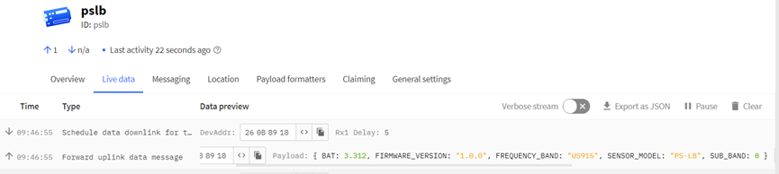
Sensor Model: For D2x-LB, this value is 0x19
Firmware Version: 0x0100, Means: v1.0.0 version
Frequency Band:
*0x01: EU868
*0x02: US915
*0x03: IN865
*0x04: AU915
*0x05: KZ865
*0x06: RU864
*0x07: AS923
*0x08: AS923-1
*0x09: AS923-2
*0x0a: AS923-3
*0x0b: CN470
*0x0c: EU433
*0x0d: KR920
*0x0e: MA869
Sub-Band:
AU915 and US915:value 0x00 ~ 0x08
CN470: value 0x0B ~ 0x0C
Other Bands: Always 0x00
Battery Info:
Check the battery voltage.
Ex1: 0x0B45 = 2885mV
Ex2: 0x0B49 = 2889mV
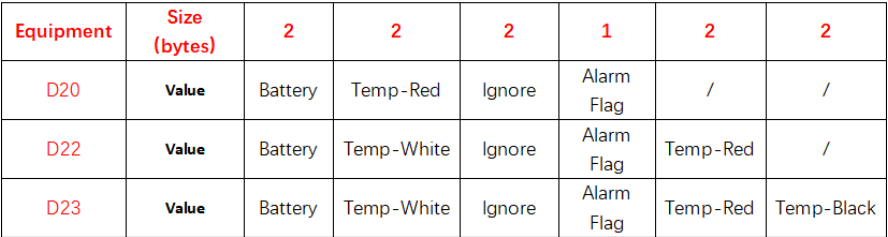
2.3.2 Sensor Data. FPORT=2
D2x-LB will uplink below payload via FPORT=2 after Joined LoRaWAN Network.
Size (bytes) | 2 | 2 | 2 | 1 | 2 | 2 |
|---|---|---|---|---|---|---|
| Value | ignore |
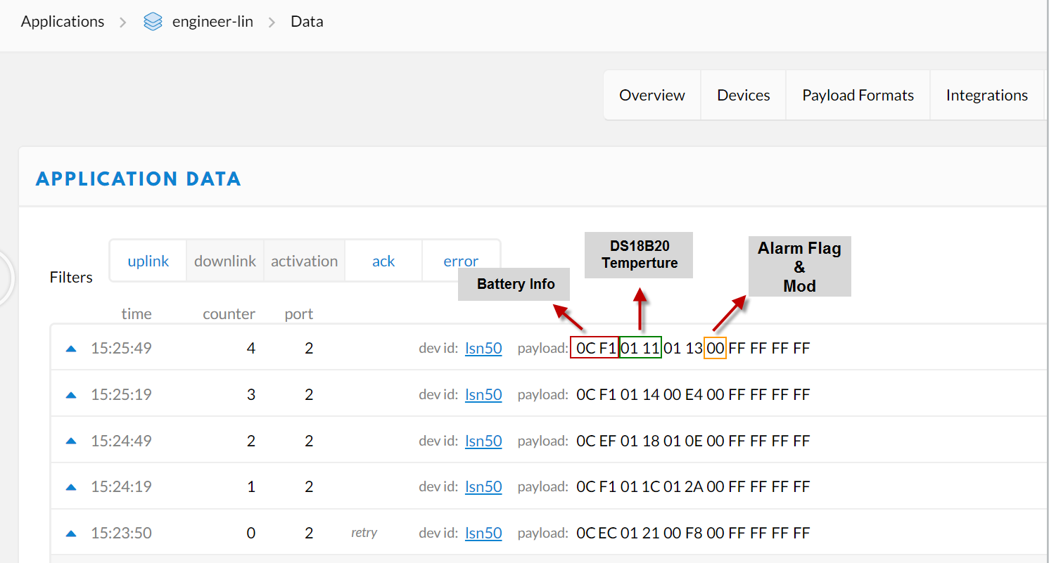
Battery:
Sensor Battery Level.
Ex1: 0x0B45 = 2885mV
Ex2: 0x0B49 = 2889mV
Temperature RED or Temperature White :
This point to the Red probe in D20-LB or the probe of D22-LB/D23-LB White
Example:
If payload is: 0105H: (0105 & 8000 == 0), temp = 0105H /10 = 26.1 degree
If payload is: FF3FH : (FF3F & 8000 == 1) , temp = (FF3FH - 65536)/10 = -19.3 degrees.
(FF3F & 8000:Judge whether the highest bit is 1, when the highest bit is 1, it is negative)
Temperature White:
This point to the Red probe in D22-LB/D23-LB
Example:
If payload is: 0105H: (0105 & 8000 == 0), temp = 0105H /10 = 26.1 degree
If payload is: FF3FH : (FF3F & 8000 == 1) , temp = (FF3FH - 65536)/10 = -19.3 degrees.
(FF3F & 8000:Judge whether the highest bit is 1, when the highest bit is 1, it is negative)
Temperature Black:
This point to the BLACK probe in D23-LB
Example:
If payload is: 0105H: (0105 & 8000 == 0), temp = 0105H /10 = 26.1 degree
If payload is: FF3FH : (FF3F & 8000 == 1) , temp = (FF3FH - 65536)/10 = -19.3 degrees.
(FF3F & 8000:Judge whether the highest bit is 1, when the highest bit is 1, it is negative)
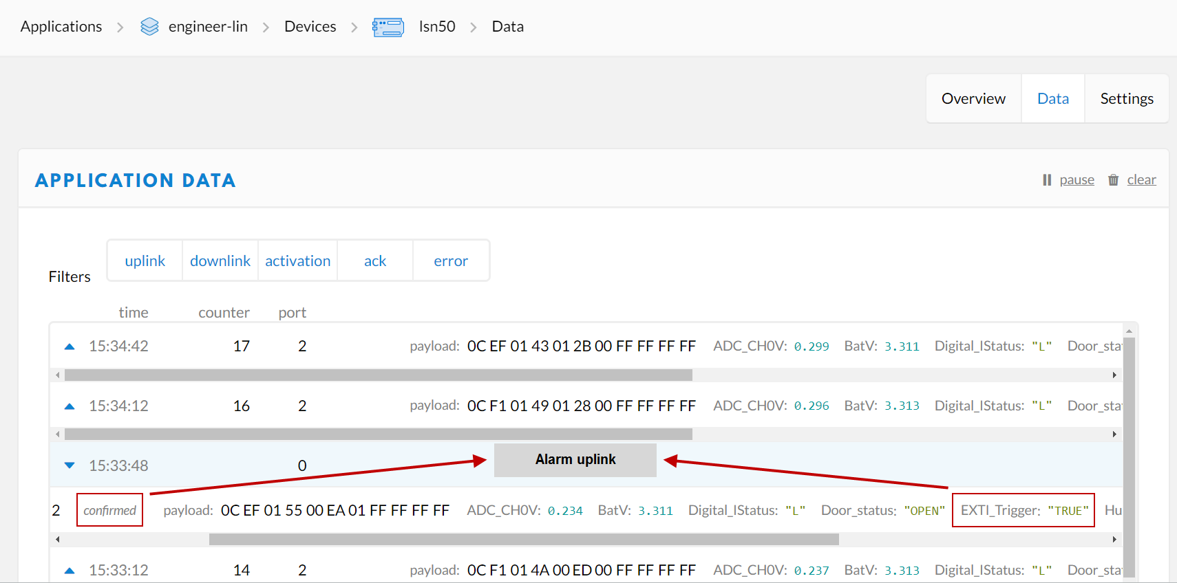
Alarm Flag& MOD:
Example:
If payload & 0x01 = 0x01 --> This is an Alarm Message
If payload & 0x01 = 0x00 --> This is a normal uplink message, no alarm
If payload >> 2 = 0x00 --> means MOD=1, This is a sampling uplink message
If payload >> 2 = 0x31 --> means MOD=31, this message is a reply message for polling, this message contains the alarm settings. see this link for detail.
Decode corresponding probe color:
D20:
Red <--> C1
D22:
White <--> C1 Red <--> C2
D23:
White <-->C1 Red <--> C2 Black <--> C3
2.4 Payload Decoder file
In TTN, use can add a custom payload so it shows friendly.
In the page Applications --> Payload Formats --> Custom --> decoder to add the decoder from: https://github.com/dragino/dragino-end-node-decoder
2.5 Temperature Alarm Feature
D2x-LB work flow with Alarm feature.
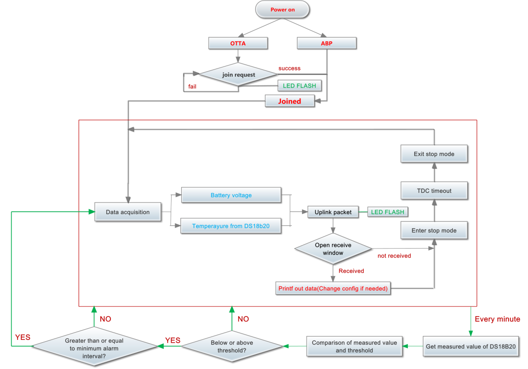
User can use AT+18ALARM command to set the alarm low limit or high limit. Device will check the temperature every minute, if the temperature lower than low limit or greater than high limit. D2x-LB will send an Alarm packet base on Confirmed Uplink Mode to server.
Below is an example of the Alarm Packet.
2.6 Frequency Plans
The D2x-LB uses OTAA mode and below frequency plans by default. If user want to use it with different frequency plan, please refer the AT command sets.
http://wiki.dragino.com/xwiki/bin/view/Main/End%20Device%20Frequency%20Band/
2.7 Firmware Change Log
Firmware download link:
https://www.dropbox.com/sh/gf1glloczbzz19h/AABbuYI4WY6VdAmpXo6o1V2Ka?dl=0
3. Configure D2x-LB
3.1 Configure Methods:
D2x-LB supports below configure method:
- AT Command via Bluetooth Connection (Recommand Way): BLE Configure Instruction.
- AT Command via UART Connection : See FAQ.
- LoRaWAN Downlink. Instruction for different platforms: See IoT LoRaWAN Server section.
3.2 General Commands
These commands are to configure:
- General system settings like: uplink interval.
- LoRaWAN protocol & radio related command.
They are same for all Dragino Devices which support DLWS-005 LoRaWAN Stack. These commands can be found on the wiki:
http://wiki.dragino.com/xwiki/bin/view/Main/End%20Device%20AT%20Commands%20and%20Downlink%20Command/
3.3 Commands special design for D2x-LB
These commands only valid for D2x-LB, as below:
3.3.1 Set Transmit Interval Time
Feature: Change LoRaWAN End Node Transmit Interval.
AT Command: AT+TDC
| Command Example | Function | Response |
|---|---|---|
| AT+TDC=? | Show current transmit Interval | 30000 |
| AT+TDC=60000 | Set Transmit Interval | OK |
Downlink Command: 0x01
Format: Command Code (0x01) followed by 3 bytes time value.
If the downlink payload=0100003C, it means set the END Node's Transmit Interval to 0x00003C=60(S), while type code is 01.
- Example 1: Downlink Payload: 0100001E // Set Transmit Interval (TDC) = 30 seconds
- Example 2: Downlink Payload: 0100003C // Set Transmit Interval (TDC) = 60 seconds
3.3.2 Get Device Status
Send a LoRaWAN downlink to ask device send Alarm settings.
- Downlink Payload: 0x26 01
Sensor will upload Device Status via FPORT=5. See payload section for detail.
3.3.3 Set Alarm Thredhold
1. Set for All Probes:
AT+18ALARM=min,max
- When min=0, and max≠0, Alarm trigger when higher than max
- When min≠0, and max=0, Alarm trigger when lower than min
- When min≠0 and max≠0, Alarm trigger when higher than max or lower than min
Example:
AT+18ALARM=-10,30 // Alarm when < -10 or higher than 30.
- Downlink Payload:
0x(0B F6 1E) // Same as AT+18ALARM=-10,30
(note: 0x1E= 30, 0xF6 means: 0xF6-0x100 = -10)
2. Set for Separate Probe:
AT+18ALARM=min,max,index
Index:
- 1: Temperature_Red
- 2: Temperature_White
- 3: Temperature_Black
Example:
AT+18ALARM=-10,30,1 // Alarm when temperature_red < -10 or higher than 30.
- Downlink Payload:
0x(0B F6 1E 01) // Same as AT+18ALARM=-10,30,1
(note: 0x1E= 30, 0xF6 means: 0xF6-0x100 = -10)
3.3.4 Set Alarm Interval
The shortest time of two Alarm packet. (unit: min)
- AT Command:
AT+ATDC=30 // The shortest interval of two Alarm packets is 30 minutes, Means is there is an alarm packet uplink, there won't be another one in the next 30 minutes.
- Downlink Payload:
0x(0D 00 1E) ---> Set AT+ATDC=0x 00 1E = 30 minutes
3.3.5 Get Alarm settings (什么FPORT?)
Send a LoRaWAN downlink to ask device send Alarm settings.
- Downlink Payload: 0x0E 01
Example:
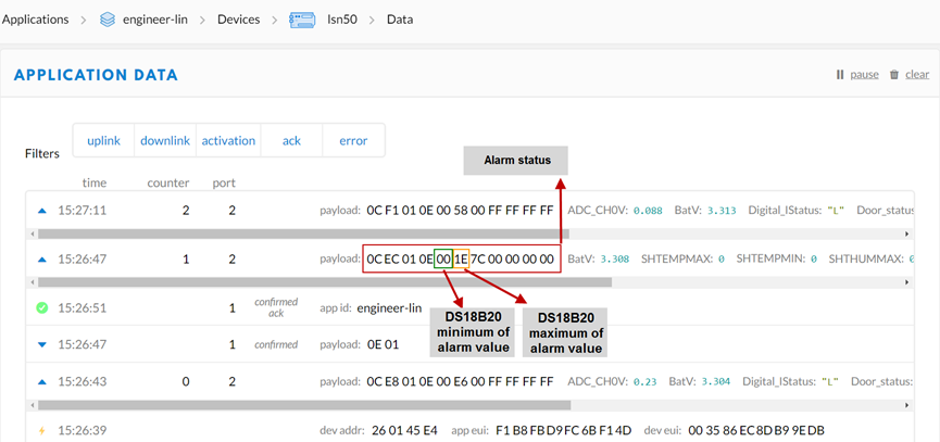
Explain:
- Alarm & MOD bit is 0x7C, 0x7C >> 2 = 0x31: Means this message is the Alarm settings message.
3.3.6 Set Interrupt Mode
Feature, Set Interrupt mode for GPIO_EXIT.
AT Command: AT+INTMOD
| Command Example | Function | Response |
|---|---|---|
| AT+INTMOD=? | Show current interrupt mode | 0 |
| AT+INTMOD=2 | Set Transmit Interval | OK |
Downlink Command: 0x06
Format: Command Code (0x06) followed by 3 bytes.
This means that the interrupt mode of the end node is set to 0x000003=3 (rising edge trigger), and the type code is 06.
- Example 1: Downlink Payload: 06000000 // Turn off interrupt mode
- Example 2: Downlink Payload: 06000003 // Set the interrupt mode to rising edge trigger
4. Battery & Power Consumption
D2x-LB use ER26500 + SPC1520 battery pack. See below link for detail information about the battery info and how to replace.
Battery Info & Power Consumption Analyze .
5. OTA firmware update
Please see this link for how to do OTA firmware update: http://wiki.dragino.com/xwiki/bin/view/Main/Firmware%20OTA%20Update%20for%20Sensors/
6. FAQ
6.1 How to use AT Command via UART to access device?
6.2 How to update firmware via UART port?
6.3 How to change the LoRa Frequency Bands/Region?
You can follow the instructions for how to upgrade image.
When downloading the images, choose the required image file for download.
7. Order Info
Part Number: D20-LB-XX / D22-LB-XX / D23-LB-XX
XX: The default frequency band
- AS923: LoRaWAN AS923 band
- AU915: LoRaWAN AU915 band
- EU433: LoRaWAN EU433 band
- EU868: LoRaWAN EU868 band
- KR920: LoRaWAN KR920 band
- US915: LoRaWAN US915 band
- IN865: LoRaWAN IN865 band
- CN470: LoRaWAN CN470 band
8. Packing Info
Package Includes:
- D2x-LB LoRaWAN Temperature Sensor
Dimension and weight:
- Device Size: cm
- Device Weight: g
- Package Size / pcs : cm
- Weight / pcs : g
9. Support
- Support is provided Monday to Friday, from 09:00 to 18:00 GMT+8. Due to different timezones we cannot offer live support. However, your questions will be answered as soon as possible in the before-mentioned schedule.
- Provide as much information as possible regarding your enquiry (product models, accurately describe your problem and steps to replicate it etc) and send a mail to support@dragino.com