Table of Contents:
- 1. Introduction
- 2. How to use
- 3. Configure WSC2-L
- 4. Power consumption and battery
- 5. Main Process Unit WSC2-L
- 7. OTA Firmware update
- 8. FAQ
- 9. Trouble Shooting
- 10. Order Info
- 11. Support
1. Introduction
1.1 Overview
Dragino WSC2-L Weather Station Kit is designed for measuring atmospheric conditions to provide information for weather forecasts and to study the weather and climate. WSC2-L Weather Station kit includes a 9 in 1 weather station and a LoRaWAN transmitter.
The 9 in 1 weather station kit can measure below values: Wind Speed, Wind Direction, Temperature, Humidity, Air Pressure, Illumination, PM2.5, PM10 & Noise. The LoRaWAN transmitter use RS485 interface to communicate with the 9 in 1 weather station. It can also connect 3rd party RS485 sensors to measure more environment data. It also has a pulse counting input which can be used to connect tipping bucket Rain Gauge.
WSC2-L is full compatible with LoRaWAN Class A protocol, it can work with standard LoRaWAN gateway.
1.2 Features
- LoRaWAN 1.0.3 Class A
- Bands: CN470/EU433/KR920/US915/EU868/AS923/AU915/IN865
- Ultra-low power consumption
- Built-in sensors: Wind Speed, Wind Direction, Temperature, Humidity, Air Pressure, Illumination, PM2.5, PM10
- RS485 Interface for 3rd Sensors
- Support tipping bucket Rain Gauge
- Support Bluetooth v5.1 and LoRaWAN remote configure
- Support wireless OTA update rmware
- AT Commands to change parameters
- Downlink to change configure
- IP66 Waterproof Enclosure
- 1000mAh Rechargeable Lion Battery
- Input and Recharge power : 12v
1.3 Specification
Wind Speed:
- Range:0~60m/s
- Accuracy:±(0.2m/s±0.02*v)(v : the wind speed)
- Ultrasonic measurement,no start wind strength needed
Wind Direction:
- Range:0~3599
- Accuracy:+3°
- Ultrasonic measurement,no start wind strength needed
- Built-in electronic compass. No need to consider installation direction
Temperature:
- Range:-40C~+80C
- Accuracy:+0.5C
Humidity:
- Range:0 ~99% RH
- Accuracy Tolerance :Typ +3% RH
Air Pressure:
- Accuracy: ±0.15kPa@25℃ 101kPa
- Range: 0-120kPa
Noise:
- Range: 30dB~120dB
- Accuracy: +0.5dB
PM2.5:
- Range: 0-1000ug/m3
- Accuracy: ±3%FS
- Resolution:1ug/m3
PM10:
- Range: 0-1000ug/m3
- Accuracy: +3%FS
- Resolution:1ug/m3
llumination:
- Range: 0-200k Lux
- Accuracy:+7%(25 ℃)
2. How to use
2.1 Installation
Below is an installation example for the weather station. Field installation example can be found at Appendix I: Field Installation Photo.

Wiring:
- WSC2-L and sensors all powered by solar power via MPPT
- WSC2-L Weather Station Kit already include 9 sensors.
- Possible to add optional 3rd sensors to measure more parameter
Notice 1:
- All weather sensors and WSC2-L are powered by MPPT solar recharge controller. MPPT is connected to solar panel and storage battery.
- Weather sensors won't work if solar panel and storage battery fails.
Notice 2:
Due to shipment and importation limitation, user is better to purchase below parts locally:
- Solar Panel
- Storage Battery
- MPPT Solar Recharger
- Cabinet.
2.2 How it works?
Each WSC2-L is shipped with a worldwide unique set of OTAA keys. To use WSC2-L in a LoRaWAN network, user needs to input the OTAA keys in LoRaWAN network server. After finish installation as above. Create WSC2-L in your LoRaWAN server and Power on WSC2-L , it can join the LoRaWAN network and start to transmit sensor data. The default period for each uplink is 20 minutes.
2.3 Example to use for LoRaWAN network
This section shows an example for how to join the TTN V3 LoRaWAN IoT server. Usages with other LoRaWAN IoT servers are of similar procedure.
Assume the DLOS8 is already set to connect to TTN V3 network . We need to add the WSC2-L device in TTN V3:
Step 1: Create a device in TTN V3 with the OTAA keys from WSC2-L.
Each WSC2-L is shipped with a sticker with the default device EUI as below:

User can enter these keys in the LoRaWAN Server portal. Below is TTN V3 screen shot:
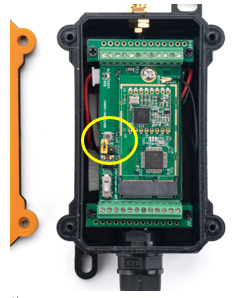
Put a Jumper on JP2 to power on the device. ( The Jumper must be in FLASH position).
Add APP EUI in the application.


Choose Manually to add WSC2-L

Add APP KEY and DEV EUI

Step 2: Power on WSC2-L, it will start to join TTN server. After join success, it will start to upload sensor data to TTN V3 and user can see in the panel.

2.4 Uplink Payload
Uplink payloads include two types: Valid Sensor Value and other status / control command.
- Valid Sensor Value: Use FPORT=2
- Other control command: Use FPORT other than 2.
2.4.1 Uplink FPORT=5, Device Status
Uplink the device configures with FPORT=5. Once WSC2-L Joined the network, it will uplink this message to the server. After first uplink, WSC2-L will uplink Device Status every 12 hours
User can also use downlink command(0x2301) to ask WSC2-L to resend this uplink
| Size(bytes) | 1 | 2 | 1 | 1 | 2 | 3 |
|---|---|---|---|---|---|---|
| Value | Sensor Model | Firmware Version | Frequency Band | Sub-band | BAT | Weather Sensor Types |

Example Payload (FPort=5): 
Sensor Model:
For WSC2-L, this value is 0x0D.
Firmware Version:
0x0100, Means: v1.0.0 version.
Frequency Band:
0x01: EU868
0x02: US915
0x03: IN865
0x04: AU915
0x05: KZ865
0x06: RU864
0x07: AS923
0x08: AS923-1
0x09: AS923-2
0x0a: AS923-3
Sub-Band:
value 0x00 ~ 0x08(only for CN470, AU915,US915. Others are0x00)
BAT:
shows the battery voltage for WSC2-L MCU.
Ex1: 0x0BD6/1000 = 3.03 V
Weather Sensor Types:
| Byte3 | Byte2 | Byte1 |
Bit = 1 means this sensor is connected, Bit=0 means this sensor is not connected
| Byte3 | Bit23 | Bit22 | Bit21 | Bit20 | Bit19 | Bit18 | Bit17 | Bit16 |
| N/A | Customize-A4 | Customize-A3 | Customize-A2 | Customize-A1 | N/A | N/A | N/A | |
| Byte2 | Bit15 | Bit14 | Bit13 | Bit12 | Bit11 | Bit10 | Bit9 | Bit8 |
| N/A | N/A | N/A | N/A | N/A | N/A | N/A | N/A | |
| Byte1 | Bit7 | Bit6 | Bit5 | Bit4 | Bit3 | Bit2 | Bit1 | Bit0 |
| WSS-07 | WSS-06 | WSS-05 | WSS-04 | WSS-03 | WSS-02 | WSS-01 | N/A |
Eg: 0x1000FE = 1 0000 0000 0000 1111 1110(b)
External sensors detected by WSC2-L include :
custom sensor A1,
PAR sensor (WSS-07),
Total Solar Radiation sensor (WSS-06),
CO2/PM2.5/PM10 (WSS-03),
Wind Speed/Direction (WSS-02)
User can also use downlink command(0x26 01) to ask WSC2-L to resend this uplink :
Downlink:0x26 01

2.4.2 Uplink FPORT=2, Real time sensor value
WSC2-L will send this uplink after Device Config uplink once join LoRaWAN network successfully. And it will periodically send this uplink. Default interval is 20 minutes and can be changed.
Uplink uses FPORT=2 and every 20 minutes send one uplink by default.
The upload length is dynamic, depends on what type of weather sensors are connected. The uplink payload is combined with sensor segments. As below:
Uplink Payload:
| Sensor Segment 1 | Sensor Segment 2 | …… | Sensor Segment n |
Sensor Segment Define:
| Type Code | Length (Bytes) | Measured Value |
Sensor Type Table:
| Sensor Type | Type Code | Range | Length( Bytes) | Example |
| Wind Speed | 0x01 | Speed: 0 ~ 60m/s | 0x03 | 0x0024/10=3.6m/s (0x02FE: No Sensor, 0x02EE: Value Error) 0x02=2 (0x14: No Sensor, 0x15: Value Error) |
| Wind Direction | 0x02 | Angel: 0 ~ 360° | 0x03 | 0x02C9/10=66.6°(0x0EFE: No Sensor,0x0EFF: Value Error) 0X03=3(ENE) (0x14: No Sensor,0x15: Value Error) |
| Illumination | 0x03 | 0~200000kLux | 0x02 | 0x04D2*10=12340kLux (0x4EFE: No Sensor,0x4EFF: Value Error) |
| Rain / Snow | 0x04 | 0A: No, 01 Yes. | 0x01 | 0x00 (00) No Rain or snow detected (0x02: No Sensor,0x03: Value Error) |
| CO2 | 0x05 | 0~5000ppm | 0x02 | 0x0378=888ppm (0x14FE: No Sensor,0x14FF: Value Error) |
| Temperature | 0x06 | -30℃~70℃ | 0x02 | 0xFFDD/10=-3.5℃ (0x02FE: No Sensor,0x02FF: Value Error) |
| Humidity | 0x07 | 0~100%RH | 0x02 | 0x0164/10=35.6%RH (0x03FE: No Sensor,0x03FF: Value Error) |
| Pressure | 0x08 | 10~1100hPa | 0x02 | 0x2748/10=1005.6hPa (0x00: No Sensor,0x01: Value Error) |
| Rain Gauge | 0x09 | 0mm~100mm(Rainfall in the last 24 hours) | 0x02 | 0x0050/10=8mm (Rainfall within the 24 hours:8.0mm) (0x03FE: No Sensor,0x03FF: Value Error) |
| PM2.5 | 0x0A | 0~1000μg/m3 | 0x02 | 0x0023=35μg/m3 (0x03FE: No Sensor,0x03FF: Value Error) |
| PM10 | 0x0B | 0~1000μg/m3 | 0x02 | 0x002D=45μg/m3 (0x03FE: No Sensor,0x03FF: Value Error) |
| PAR | 0x0C | 0~2500μmol/m2•s | 0x02 | 0x00B3=179μmol/m2•s (0x09FE: No Sensor,0x09FF: Value Error) |
Total Solar Radiation | 0x0D | 0~2000W/m2 | 0x02 | 0x0073/10=11.5W/m2(0x4EFE: No Sensor,0x4EFF: Value Error) |
Below is an example payload: 
When sending this payload to LoRaWAN server. WSC2-L will send this in one uplink or several uplinks according to LoRaWAN spec requirement. For example, total length of Payload is 54 bytes.
When WSC2-L sending in US915 frequency DR0 data rate. Because this data rate has limitation of 11 bytes payload for each uplink. The payload will be split into below packets and uplink.
Uplink 1: 
Uplink 2: 
When WSC2-L sending in EU868 frequency DR0 data rate. The payload will be split into below packets and uplink:
Uplink 1: 
Uplink 2: 
2.4.3 Decoder in TTN V3
In LoRaWAN platform, user only see HEX payload by default, user needs to use payload formatters to decode the payload to see human-readable value.
Download decoder for suitable platform from: https://github.com/dragino/dragino-end-node-decoder
and put as below:

2.5 Show data on Application Server
Application platform provides a human friendly interface to show the sensor data, once we have sensor data in TTN V3, we can use Datacake to connect to TTN V3 and see the data in Datacake. Below are the steps:
Step 1: Be sure that your device is programmed and properly connected to the LoRaWAN network.
Step 2: Configure your Application to forward data to Datacake you will need to add integration. Go to TTN V3 Console --> Applications --> Integrations --> Add Integrations.

Add TagoIO:

Authorization:

In TagoIO console (https://admin.tago.io//) , add WSC2-L:

2.6 Frequency Plans
The WSC2-L uses OTAA mode and below frequency plans by default. Each frequency band use different firmware, user update the firmware to the corresponding band for their country.
http://wiki.dragino.com/xwiki/bin/view/Main/End%20Device%20Frequency%20Band/
3. Configure WSC2-L
3.1 Configure Methods
WSC2-L supports below configure method:
- AT Command via Bluetooth Connection (Recommended): BLE Configure Instruction.
- AT Command via UART Connection : See UART Connection.
- LoRaWAN Downlink. Instruction for different platforms: See IoT LoRaWAN Server section.
3.2 General Commands
These commands are to configure:
- General system settings like: uplink interval.
- LoRaWAN protocol & radio related command.
They are same for all Dragino Devices which support DLWS-005 LoRaWAN Stack. These commands can be found on the wiki:
http://wiki.dragino.com/xwiki/bin/view/Main/End%20Device%20AT%20Commands%20and%20Downlink%20Command/
3.3 Commands special design for WSC2-L
These commands only valid for WSC2-L, as below:
3.3.1 Set Transmit Interval Time
Feature: Change LoRaWAN End Node Transmit Interval.
AT Command: AT+TDC
| Command Example | Function | Response |
| AT+TDC=? | Show current transmit Interval | 30000 |
| AT+TDC=60000 | Set Transmit Interval | OK |
Downlink Command: 0x01
Format: Command Code (0x01) followed by 3 bytes time value.
If the downlink payload=0100003C, it means set the END Node's Transmit Interval to 0x00003C=60(S), while type code is 01.
- Example 1: Downlink Payload: 0100001E // Set Transmit Interval (TDC) = 30 seconds
- Example 2: Downlink Payload: 0100003C // Set Transmit Interval (TDC) = 60 seconds
3.3.2 Set Emergency Mode
Feature: In emergency mode, WSC2-L will uplink data every 1 minute.
AT Command:
| Command Example | Function | Response |
| AT+ALARMMOD=1 | Enter emergency mode. Uplink every 1 minute | OK |
| AT+ALARMMOD=0 | Exit emergency mode. Uplink base on TDC time | OK |
Downlink Command:
- 0xE101 Same as: AT+ALARMMOD=1
- 0xE100 Same as: AT+ALARMMOD=0
3.3.3 Add or Delete RS485 Sensor
Feature: User can add or delete 3rd party sensor as long they are RS485/Modbus interface,baud rate support 9600.Maximum can add 4 sensors.
AT Command:
AT+DYSENSOR=Type_Code, Query_Length, Query_Command , Read_Length , Valid_Data ,has_CRC,timeout
Type_Code range: A1 ~ A4
Query_Length: RS485 Query frame length, Value cannot be greater than 10
Query_Command: RS485 Query frame data to be sent to sensor, cannot be larger than 10 bytes
Read_Length: RS485 response frame length supposed to receive. Max can receive
Valid_Data: valid data from RS485 Response, Valid Data will be added to Payload and upload via LoRaWAN.
has_CRC: RS485 Response crc check (0: no verification required 1: verification required). If CRC=1 and CRC error, valid data will be set to 0.
timeout: RS485 receive timeout (uint:ms). Device will close receive window after timeout
Example:
User need to change external sensor use the type code as address code.
With a 485 sensor, after correctly changing the address code to A1, the RS485 query frame is shown in the following table:

The response frame of the sensor is as follows:

Then the following parameters should be:
- Address_Code range: A1
- Query_Length: 8
- Query_Command: A103000000019CAA
- Read_Length: 8
- Valid_Data: 23 (Indicates that the data length is 2 bytes, starting from the 3th byte)
- has_CRC: 1
- timeout: 1500 (Fill in the test according to the actual situation)
So the input command is:
AT+DYSENSOR=A1,8,A103000000019CAA,8,24,1,1500
In every sampling. WSC2-L will auto append the sensor segment as per this structure and uplink.
| Type Code | Length (Bytes) | Measured Value |
|---|---|---|
| A1 | 2 | 0x000A |
Related commands:
AT+DYSENSOR=A1,0 --> Delete 3rd party sensor A1.
AT+DYSENSOR --> List All 3rd Party Sensor. Like below:
Downlink Command:
delete custom sensor A1:
- 0xE5A1 Same as: AT+DYSENSOR=A1,0
Remove all custom sensors
- 0xE5FF
3.3.4 RS485 Test Command
AT Command:
| Command Example | Function | Response |
|---|---|---|
| AT+RSWRITE=xxxxxx | Send command to 485 sensor. Range : no more than 10 bytes | OK |
Eg: Send command 01 03 00 00 00 01 84 0A to 485 sensor
AT+RSWRITE=0103000001840A
Downlink Command:
- 0xE20103000001840A Same as: AT+RSWRITE=0103000001840A
3.3.5 RS485 response timeout
Feature: Set or get extended time to receive 485 sensor data.
AT Command:
| Command Example | Function | Response |
|---|---|---|
| AT+DTR=1000 | Set response timeout to: Range : 0~10000 | OK |
Downlink Command:
Format: Command Code (0xE0) followed by 3 bytes time value.
If the downlink payload=E0000005, it means set the END Node's Transmit Interval to 0x000005=5(S), while type code is E0.
- Example 1: Downlink Payload: E0000005 // Set Transmit Interval (DTR) = 5 seconds
- Example 2: Downlink Payload: E000000A // Set Transmit Interval (DTR) = 10 seconds
3.3.6 Set Sensor Type
Feature: Set sensor in used. If there are 6 sensors, user can set to only send 5 sensors values.
See definition for the sensor type.
| Byte3 | Bit23 | Bit22 | Bit21 | Bit20 | Bit19 | Bit18 | Bit17 | Bit16 |
| A4 | A3 | A2 | A1 | |||||
| Byte2 | Bit15 | Bit14 | Bit13 | Bit12 | Bit11 | Bit10 | Bit9 | Bit8 |
| Solar Radiation | PAR | PM10 | PM2.5 | Rain | Air | |||
| Byte1 | Bit7 | Bit6 | Bit5 | Bit4 | Bit3 | Bit2 | Bit1 | Bit0 |
| Humidity | Temperature | CO2 | Rain/Snow | illuminance | Wind | Wind Speed | BAT |
AT Command:
| Command Example | Function | Response |
|---|---|---|
| AT+STYPE=80221 | Set sensor types | OK |
Eg: The setting command AT+STYPE=80221 means:
| Byte3 | Bit23 | Bit22 | Bit21 | Bit20 | Bit19 | Bit18 | Bit17 | Bit16 |
| 0 | 0 | 0 | 0 | 1 | 0 | 0 | 0 | |
| Byte2 | Bit15 | Bit14 | Bit13 | Bit12 | Bit11 | Bit10 | Bit9 | Bit8 |
| 0 | 0 | 0 | 0 | 0 | 0 | 1 | 0 | |
| Byte1 | Bit7 | Bit6 | Bit5 | Bit4 | Bit3 | Bit2 | Bit1 | Bit0 |
| 0 | 0 | 1 | 0 | 0 | 0 | 0 | 1 |
So WSC2-L will upload the following data: Custom Sensor A1, Rain Gauge,CO2,BAT.
Downlink Command:
- 0xE400080221 Same as: AT+STYPE=80221
Note:
1. The sensor type will not be saved to flash, and the value will be updated every time the sensor is restarted or rescanned.
3.4 Add 3rd RS485 / Modbus Sensor
3.4.1 Hardware Connection
3.4.2 Software Setup
3.4.3 Payload
3.5 Add tipping bucket Rain Guage
3.5.1 Hardware Connection
3.5.2 Calculating & Decode
4. Power consumption and battery
4.1 Total Power Consumption
Dragino Weather Station serial products include the main process unit (WSC2-L) and various sensors. The total power consumption equal total power of all above units. The power consumption for main process unit WSC2-L is 18ma @ 12v. and the power consumption of each sensor can be found on the Sensors chapter.
4.2 Reduce power consumption
The main process unit WSC2-L is set to LoRaWAN Class C by default. If user want to reduce the power consumption of this unit, user can set it to run in Class A. In Class A mode, WSC2-L will not be to get real-time downlink command from IoT Server.
4.3 Battery
All sensors are only power by external power source. If external power source is off. All sensor won't work.
Main Process Unit WSC2-L is powered by both external power source and internal 1000mAh rechargeable battery. If external power source is off, WSC2-L still runs and can send periodically uplinks, but the sensors value will become invalid. External power source can recharge the 1000mAh rechargeable battery.
5. Main Process Unit WSC2-L
WSC2-L is the main process unit in Dragino Weather Station solution. WSC2-LB is an an outdoor LoRaWAN RS485 end node. It is powered by external 12v solar power and have a built-in li-on backup battery.
WSC2-L reads value from various sensors and upload these sensor data to IoT server via LoRaWAN wireless protocol.
WSC2-L is full compatible with LoRaWAN Class C protocol, it can work with standard LoRaWAN gateway.
WSC2-L Supports BLE configure and wireless OTA update which make user easy to use.
Each WSC2-L is pre-load with a set of unique keys for LoRaWAN registration, register these keys to local LoRaWAN server and it will auto connect after power on.
5.1 Features
- LoRaWAN v1.0.3 Class A protocol.
- RS485 / Modbus protocol
- Frequency Bands: CN470/EU433/KR920/US915/EU868/AS923/AU915
- AT Commands to change parameters
- Downlink to change configure
- Powered by external 12v battery
- Back up rechargeable 1000mAh battery
- IP Rating: IP65
- Support default sensors or 3rd party RS485 sensors
- Support Bluetooth v5.1 and LoRaWAN remote configure
- Support wireless OTA update firmware
- Wall Attachable.
5.2 Power Consumption
WSC2-L (without external sensor): Idle: 4mA, Transmit: max 40mA
5.3 Storage & Operation Temperature
-20°C to +60°C
5.4 Sleep mode and working mode
Deep Sleep Mode: Sensor doesn't have any LoRaWAN activate. This mode is used for storage and shipping to save battery life.
Working Mode: In this mode, Sensor will work as LoRaWAN Sensor to Join LoRaWAN network and send out sensor data to server. Between each sampling/tx/rx periodically, sensor will be in IDLE mode), in IDLE mode, sensor has the same power consumption as Deep Sleep mode.
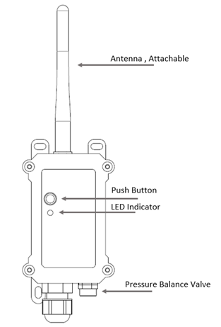
5.5 Button & LEDs
| Behavior on ACT | Function | Action |
|---|---|---|
| Pressing ACT between 1s < time < 3s | Send an uplink | If sensor is already Joined to LoRaWAN network, sensor will send an uplink packet, blue led will blink once. |
| Pressing ACT for more than 3s | Active Device | Green led will fast blink 5 times, device will enter OTA mode for 3 seconds. And then start to JOIN LoRaWAN network. |
| Fast press ACT 5 times. | Deactivate Device | Red led will solid on for 5 seconds. Means device is in Deep Sleep Mode. |
5.6 BLE connection
WSC2-L supports BLE remote configure.
BLE can be used to configure the parameter of sensor or see the console output from sensor. BLE will be only activate on below case:
- Press button to send an uplink
- Press button to active device.
- Device Power on or reset.
If there is no activity connection on BLE in 60 seconds, sensor will shut down BLE module to enter low power mode.
5.7 Pin Mapping

5.8 Mechanical
Refer LSn50v2 enclosure drawing in: https://www.dropbox.com/sh/0ir0l9jjmk6p95e/AADwWXorcKuNpPR5em7VgrEja?dl=0
5.9 Connect to RS485 Sensors
WSC2-L includes a RS485 converter PCB. Which help it easy to connect multiply RS485 sensors. Below is the photo for reference.

Hardware Design for the Converter Board please see:
https://www.dropbox.com/sh/bqyvsvitb70qtgf/AABLpD7_yxsQ_drVMxHIEI7wa?dl=0
7. OTA Firmware update
User can change firmware WSC2-L to:
- Change Frequency band/ region.
- Update with new features.
- Fix bugs.
Firmware and changelog can be downloaded from : Firmware download link
Methods to Update Firmware:
- (Recommanded way) OTA firmware update via wireless: http://wiki.dragino.com/xwiki/bin/view/Main/Firmware%20OTA%20Update%20for%20Sensors/
- Update through UART TTL interface: Instruction.
8. FAQ
8.1 What else do I need to purchase to build Weather Station?
Below is the installation photo and structure:


9. Trouble Shooting
10. Order Info
Part Number: WSC2-L-XX
XX: The default frequency band
- AS923: LoRaWAN AS923 band
- AU915: LoRaWAN AU915 band
- EU433: LoRaWAN EU433 band
- EU868: LoRaWAN EU868 band
- KR920: LoRaWAN KR920 band
- US915: LoRaWAN US915 band
- IN865: LoRaWAN IN865 band
- CN470: LoRaWAN CN470 band
11. Support
- Support is provided Monday to Friday, from 09:00 to 18:00 GMT+8. Due to different timezones we cannot offer live support. However, your questions will be answered as soon as possible in the before-mentioned schedule.
- Provide as much information as possible regarding your enquiry (product models, accurately describe your problem and steps to replicate it etc) and send a mail to support@dragino.com.