AIS01-CB -- NB-IoT/LTE-M AI Image End Node User Manual

Table of Contents:
- 1. Introduction
- 2. Use AIS01-CB to communicate with IoT Server
- 3. Configure AIS01-CB
- 3.1 Configure Methods
- 3.2 Commands special design for AIS01-CB
- 3.2.1 Set Transmit Interval Time
- 3.2.2 Set Interrupt Mode
- 3.2.3 Setting up automatic image upload data
- 3.2.4 Example Query saved historical records
- 3.2.5 Uplink log query
- 3.2.6 Set CoAP option
- 3.2.7 Set the downlink debugging mode(Since firmware v1.1.0)
- 3.2.8 Domain name resolution settings(Since firmware v1.1.1)
- 4. AT Commands Set
- 5. Clock logging
- 6. Battery & Power Consumption
- 7. Case Study
- 8. OTA Firmware update
- 9. FAQ
- 10. Order Info
- 11. Packing Info
- 12. Support
- 13. Appendix I: Field Installation Photo
1. Introduction
1.1 What is AIS01-CB
AIS01-CB is a NB-IoT/LTE-M AI Image End Node. AIS01-CB has a camera and AI processor in the probe. It can take photo , analyze the photo to get digital reading and upload to IoT server via NB-IoT/CAT-M1 network.
AIS01-CB is pre-trained to support image recognized of water meter, gas meter and power meter. It can be trained to support more image recognized for different application.
AIS01-CB can send the digital reading after recognized and it can also send the original photo via NB-IoT/CAT-M1 as well.
AIS01-CB has optional built-in SIM card and default IoT server connection version. Which makes it works with simple configuration.
AIS01-CB supports BLE configure and OTA update which make user easy to use.
AIS01-CB is powered by 8500mAh Li-SOCI2 battery, it is designed for long-term use up to several years.
1.2 Features
- For -NB Bands: B1/B2/B3/B4/B5/B8/B12/B13/B17/B18/B19/B20/B25/B28/B66/B70/B85
- For -CB Bands: B1/B2/B3/B4/B5/B8/B12/B13//B18/B19/B20/B25/B28/B66/B71/B85
- CAT-M1 / LTE-M Bands: B1/B2/B3/B4/B5/B8/B12/B13/B18/B19/B20/B25/B26/B27/B28/B66/B85
- Low power consumption
- AI Image Sensor.
- Send image to IoT server
- Recognize digits from Image and send data to IoT server
- Trained for common reading for Water Meter, Gas Meter, Power Meter
- Multiply Sampling and one uplink
- Support Interrupt uplink
- Support Bluetooth v5.1 remote configure and update firmware
- GNSS for Location Report
- Uplink via MQTT, MQTTs, TCP, UDP or CoAP
- Uplink on periodically
- Downlink to change configure
- 8500mAh Li/SOCl2 Battery
1.3 Specification
Common DC Characteristics:
- Supply Voltage: Built-in Battery , 2.6v ~ 3.6v
- Operating Temperature: -40 ~ 85°C
Camera:
- Mono: black & white
- Angle: 110°
- Image size: 64kb
- Image resolution: 640x480
- Power Consumption: 206.1mW
- Supply Voltage: DC5V
- Idel Mode: 6uA
- Take Photo: 41.22 mA and 3171 ms
- Cable Length: 150cm
- Dimension: 46.2x29x13.8 mm
I/O Interface:
- Battery output (2.6v ~ 3.6v depends on battery)
- +5v controllable output
- 3 x Interrupt or Digital IN/OUT pins
- 3 x one-wire interfaces
- 1 x UART Interface
- 1 x I2C Interface
LoRa Spec:
- Frequency Range, Band 1 (HF): 862 ~ 1020 Mhz
- Max +22 dBm constant RF output vs.
- RX sensitivity: down to -139 dBm.
- Excellent blocking immunity
Battery:
- Li/SOCI2 un-chargeable battery
- Capacity: 8500mAh
- Self-Discharge: <1% / Year @ 25°C
- Max continuously current: 130mA
- Max boost current: 2A, 1 second
Power Consumption:
- Sleep Mode: 5uA @ 3.3v
- LoRa Transmit Mode: 125mA @ 20dBm, 82mA @ 14dBm
1.4 Sleep mode and working mode
Deep Sleep Mode: Sensor doesn't have any NB-IoT activate. This mode is used for storage and shipping to save battery life.
Working Mode: In this mode, Sensor will work as NB-IoT Sensor to Join NB-IoT network and send out sensor data to server. Between each sampling/tx/rx periodically, sensor will be in IDLE mode), in IDLE mode, sensor has the same power consumption as Deep Sleep mode.
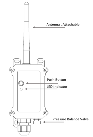
1.5 Button & LEDs
| Behavior on ACT | Function | Action |
|---|---|---|
 1~3s 1~3s | Send an uplink | If sensor is already Joined to NB-IoT/CAT-M1 network, sensor will send an uplink packet, blue led will blink once. |
 >3s >3s | Active Device | Green led will fast blink 5 times, device will enter OTA mode for 3 seconds. And then start to JOIN NB-IoT/CAT-M1 network. |
 x5 x5 | Deactivate Device | Red led will solid on for 5 seconds. Means device is in Deep Sleep Mode. |
1.6 BLE connection
AIS01-CB supports BLE remote configure.
BLE can be used to configure the parameter of sensor or see the console output from sensor. BLE will be only activate on below case:
- Press button to send an uplink
- Press button to active device.
- Device Power on or reset.
If there is no activity connection on BLE in 60 seconds, sensor will shut down BLE module to enter low power mode.
1.7 Pin Definitions
AIS01-CB use the mother board which as below.

1.7.1 Jumper JP2
Power on Device when put this jumper.
1.7.2 BOOT MODE / SW1
1) ISP: upgrade mode, device won't have any signal in this mode. but ready for upgrade firmware. LED won't work. Firmware won't run.
2) Flash: work mode, device starts to work and send out console output for further debug
1.7.3 Reset Button
Press to reboot the device.
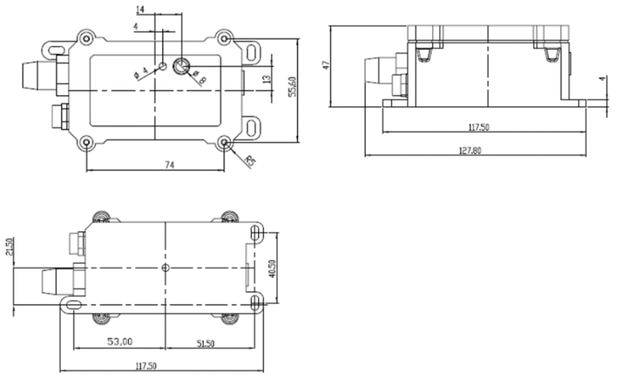
1.8 Mechanical
1.8.1 for CB version
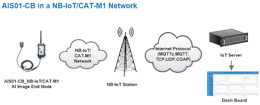
2. Use AIS01-CB to communicate with IoT Server
2.1 Send data to IoT server via NB-IoT/CAT-M1 network
The AIS01-CB is equipped with a NB-IoT module, the pre-loaded firmware in AIS01-CB will get environment data from sensors and send the value to local NB-IoT network via the NB-IoT module. The NB-IoT network will forward this value to IoT server via the protocol defined by AIS01-CB.
Below shows the network structure:
There are two version: -GE and -1T version of AIS01-CB.
GE Version: This version doesn't include SIM card or point to any IoT server. User needs to use AT Commands to configure below two steps to set AIS01-CB send data to IoT server.
- Install NB-IoT SIM card and configure APN. See instruction of Attach Network.
- Set up sensor to point to IoT Server. See instruction of Configure to Connect Different Servers.
Below shows result of different server as a glance.
| Servers | Dash Board | Comments |
| Node-Red |
| |
| DataCake |
| |
| Tago.IO |  | |
| General UDP | Raw Payload. Need Developer to design Dash Board | |
| General MQTT | Raw Payload. Need Developer to design Dash Board | |
| ThingSpeak |
| |
| ThingsBoard |
|
1T Version: This version has 1NCE SIM card pre-installed and configure to send value to ThingsEye. User Just need to select the sensor type in ThingsEyeand Activate AIS01-CB and user will be able to see data in ThingsEye. See here for ThingsEye Config Instruction.
2.2 Payload Types
To meet different server requirement, AIS01-CB supports different payload type.
Includes:
- General JSON format payload. (Type=5)
- HEX format Payload. (Type=0)
- ThingSpeak Format. (Type=1)
- ThingsBoard Format. (Type=3)
User can specify the payload type when choose the connection protocol. Example:
AT+PRO=2,0 // Use UDP Connection & hex Payload
AT+PRO=2,5 // Use UDP Connection & Json Payload
AT+PRO=3,5 // Use MQTT Connection & Json Payload
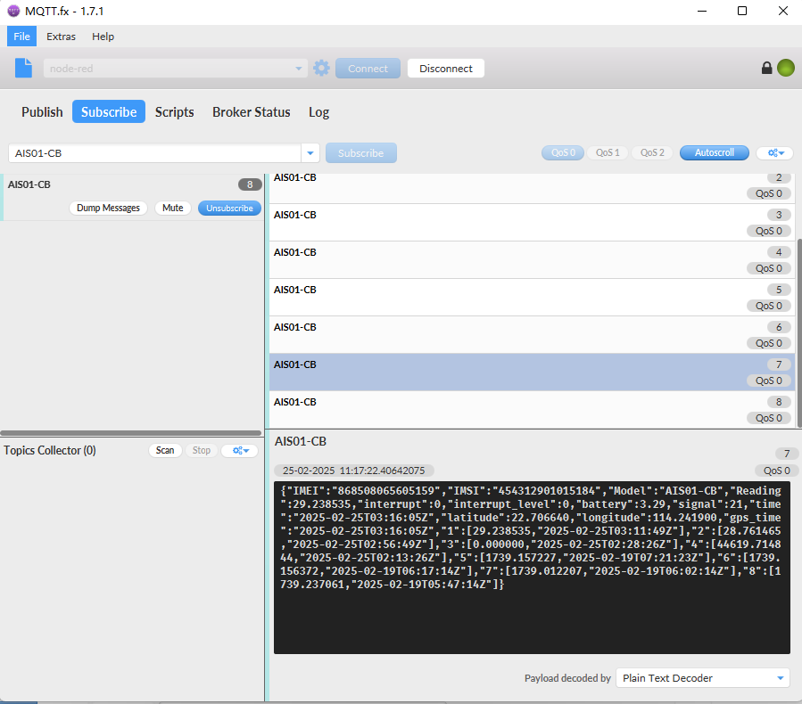
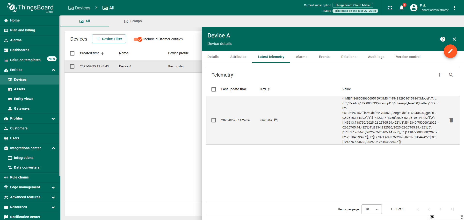
2.2.1 General Json Format(Type=5)
This is the General Json Format. As below:
{"IMEI":"868508065605159","IMSI":"454312901015184","Model":"AIS01-CB","Reading":29.238535,"interrupt":0,"interrupt_level":0,"battery":3.29,"signal":21,"time":"2025-02-25T03:16:05Z","latitude":22.706640,"longitude":114.241900,"gps_time":"2025-02-25T03:16:05Z","1":[29.238535,"2025-02-25T03:11:49Z"],"2":[28.761465,"2025-02-25T02:56:49Z"],"3":[0.000000,"2025-02-25T02:28:26Z"],"4":[44619.714844,"2025-02-25T02:13:26Z"],"5":[1739.157227,"2025-02-19T07:21:23Z"],"6":[1739.156372,"2025-02-19T06:17:14Z"],"7":[1739.012207,"2025-02-19T06:02:14Z"],"8":[1739.237061,"2025-02-19T05:47:14Z"]}
Note: from above payload:
- Reading, Interrupt, Interrupt_level, Battery, Signal, time, latitude, longitude&GPS time are the value at uplink time.
- Json entry 1 ~ 8 are the last 1 ~ 8 sampling data as specify by AT+CLOCKLOG=1,65535,15,8 Command. Each entry includes (from left to right): Reading, Sampling time.
Example:
2.2.2 HEX format Payload(Type=0)
This is the HEX Format. As below:
f868508065605159f454312901015184686e0cd4130100000000001d0003a3c767bd36b0015a791206cf32fc67bd36b00000001d0003a3c767bd34f50000001c000b9e7967bd3171
000000000000000067bd2aca0000ae4b000aeff367bd27460000000067a96efd67b586730000000067a96b7967b5776a0000000067a7388267b573e60000000067aaa72467b57062
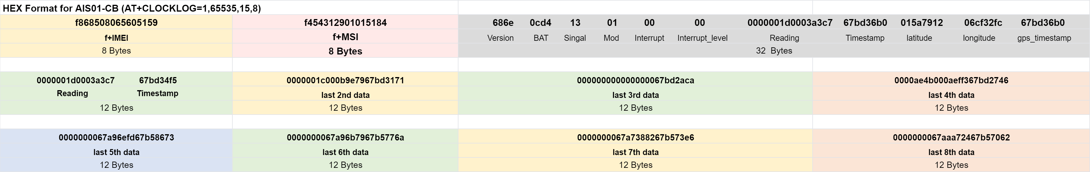

Version:
These bytes include the hardware and software version.
Higher byte: Specify Sensor Model: 0x68 for AIS01-CB
Lower byte: Specify the software version: 0x6e=110, means firmware version 1.1.0
BAT (Battery Info):
Ex1: 0x0cd4 = 3284mV
Signal Strength:
NB-IoT Network signal Strength.
Ex1: 0x13 = 19
0 -113dBm or less
1 -111dBm
2...30 -109dBm... -53dBm
31 -51dBm or greater
99 Not known or not detectable
Interrupt:
This data field shows if this packet is generated by interrupt or not.
Example:
If byte[0]&0x01=0x00 : Normal uplink packet.
If byte[0]&0x01=0x01 : Interrupt Uplink Packet.
Interrupt_level:
This byte shows whether the interrupt is triggered by a high or low level.
Ex1: 0x00 Interrupt triggered by falling edge (low level)
Ex2: 0x01 Interrupt triggered by rising edge (high level)
Reading:
The uplink integer data is the first four bytes of the Reading payload.
Ex1: 0x 0000001d(H) = 29(D)
The fractional part is the last four bytes of the uplink Reading payload.
Ex2: 0x0003a3c7(H) = 238535(D) / 1000000 = 0.238535
The total number read is:
integer part(D) + decimal part(D): 29+0.238535 = 29.238535
TimeStamp & GPS Timestamp
Unit TimeStamp Example: 67bd36b0(H) = 1740453552(D)
Put the decimal value into this link(https://www.epochconverter.com/) to get the time.
Latitude:
Example: 0x015a7912(H)=22706450(D)=22.706450
Longitude:
Example: 0x06cf32fc(H)=114242300(D)=114.242300
2.2.3 ThingsBoard Payload(Type=3)
Type3 payload special design for ThingsBoard, it will also configure other default server to ThingsBoard.
{
"IMEI": "868508065605159",
"IMSI": "454312901015184",
"Model": "AIS01-CB",
"Reading": 29.000593,
"interrupt": 0,
"interrupt_level": 0,
"battery": 3.28,
"signal": 22,
"time": "2025-02-25T06:24:15Z",
"latitude": 22.705870,
"longitude": 114.243620,
"gps_time": "2025-02-25T03:44:39Z",
"1": [143230.718750, "2025-02-25T06:14:42Z"],
"2": [145513.718750, "2025-02-25T05:59:42Z"],
"3": [545340.750000, "2025-02-25T05:44:42Z"],
"4": [3234.332520, "2025-02-25T05:29:42Z"],
"5": [173517.765625, "2025-02-25T05:14:42Z"],
"6": [111077.000000, "2025-02-25T04:59:42Z"],
"7": [177371.609375, "2025-02-25T04:44:42Z"],
"8": [124675.554688, "2025-02-25T04:29:42Z"]
}
2.2.4 ThingSpeak Payload(Type=1)
This payload meets ThingSpeak platform requirement. It includes only four fields. Form 1~4 are:
Temperature, Humidity, Battery & Signal. This payload type only valid for ThingsSpeak Platform
As below:
field1=Reading&field2=BatV&field3=Signal&field4=Interrupt&field5=Interrupt_Level

2.3 Image data
Because it takes a packet to remove the first eight bytes of flags, you need to start with the ninth byte when taking the first segment of the picture's data
Example: Payload: P1C05A0158070000FFD8FFE000104A46494600010101004800480000FFDB0043001B12141714111B1716171E1C1B2028422B28252528513A3D3042605565645F555D5B6A7899816A7190735B5D85B586909E
A3ABADAB6780BCC9BAA6C799A8ABA4FFDB0043011C1E1E2823284E2B2B4EA46E5D6EA4A4A4A4A4A4A4A4A4A4A4A4A4A4A4A4A4A4A4A4A4A4A4A4A4A4A4A4A4A4A4A4A4A4A4A4A4A4A4A4A4A4A4A
4A4A4A4A4A4A4FFC0000B080040010001012200FFC4001F0000010501010101010100000000000000000102030405060708090A0BFFC400B5100002010303020403050504040000017D0102030004110512213
1410613516107227114328191A1082342B1C11552D1F02433627282090A161718191A25262728292A3435363738393A434445464748494A535455565758595A636465666768696A737475767778797A838485
868788898A92939495969798999AA2A3A4A5A6A7A8A9AAB2B3B4B5B6B7B8B9BAC2C3C4C5C6C7C8C9CAD2D3D4D5D6D7D8D9DAE1E2E3E4E5E6E7E8E9EAF1F2F3F4F5F6F7F8F9FAFFC4001F0100030101010
101010101010000000000000102030405060708090A0BFFC400B51100020102040403040705040400010277000102031104052131061241510761711322328108144291A1B1C109233352F0156272D10A16243
4E125F11718191A262728292A35363738393A43444546
Image data=FFD8FFE000104A46494600010101004800480000FFDB0043001B12141714111B1716171E1C1B2028422B28252528513A3D3042605565645F555D5B6A7899816A7190735B5D85B586909EA3ABADAB678
0BCC9BAA6C799A8ABA4FFDB0043011C1E1E2823284E2B2B4EA46E5D6EA4A4A4A4A4A4A4A4A4A4A4A4A4A4A4A4A4A4A4A4A4A4A4A4A4A4A4A4A4A4A4A4A4A4A4A4A4A4A4A4A4A4A4A4A4A4A4A4A4
A4FFC0000B080040010001012200FFC4001F0000010501010101010100000000000000000102030405060708090A0BFFC400B5100002010303020403050504040000017D0102030004110512213141061351610
7227114328191A1082342B1C11552D1F02433627282090A161718191A25262728292A3435363738393A434445464748494A535455565758595A636465666768696A737475767778797A838485868788898A92
939495969798999AA2A3A4A5A6A7A8A9AAB2B3B4B5B6B7B8B9BAC2C3C4C5C6C7C8C9CAD2D3D4D5D6D7D8D9DAE1E2E3E4E5E6E7E8E9EAF1F2F3F4F5F6F7F8F9FAFFC4001F01000301010101010101010100
00000000000102030405060708090A0BFFC400B51100020102040403040705040400010277000102031104052131061241510761711322328108144291A1B1C109233352F0156272D10A162434E125F11718191
A262728292A35363738393A43444546
2.3.1 Image data reception instructions
Because the total number of bytes uplinked for the picture is 1892 bytes, an uplink packet can only be uplinked by 511 bytes, so it will be split into four packets for uplinking.
Example:
P1C05A0158070000FFD8FFE000104A46494600010101004800480000FFDB0043001B12141714111B1716171E1C1B2028422B28252528513A3D3042605565645F555D5B6A7899816A7190735B5D85B586909EA
3ABADAB6780BCC9BAA6C799A8ABA4FFDB0043011C1E1E2823284E2B2B4EA46E5D6EA4A4A4A4A4A4A4A4A4A4A4A4A4A4A4A4A4A4A4A4A4A4A4A4A4A4A4A4A4A4A4A4A4A4A4A4A4A4A4A4A4A4A4A4
A4A4A4A4A4A4FFC0000B080040010001012200FFC4001F0000010501010101010100000000000000000102030405060708090A0BFFC400B5100002010303020403050504040000017D01020300041105122131
410613516107227114328191A1082342B1C11552D1F02433627282090A161718191A25262728292A3435363738393A434445464748494A535455565758595A636465666768696A737475767778797A8384858
68788898A92939495969798999AA2A3A4A5A6A7A8A9AAB2B3B4B5B6B7B8B9BAC2C3C4C5C6C7C8C9CAD2D3D4D5D6D7D8D9DAE1E2E3E4E5E6E7E8E9EAF1F2F3F4F5F6F7F8F9FAFFC4001F01000301010101
01010101010000000000000102030405060708090A0BFFC400B51100020102040403040705040400010277000102031104052131061241510761711322328108144291A1B1C109233352F0156272D10A162434E
125F11718191A262728292A35363738393A43444546
2.3.2 Combined image
Combine each data packet obtained from the platform (note: the first 8 bytes of each data packet need to be deleted before combining)
Then use winhex software to convert to get the image, specific tutorial: Combined image
Below is the text of the integrated data and the image of the converted data:

2.4 ThingsEye Configuration
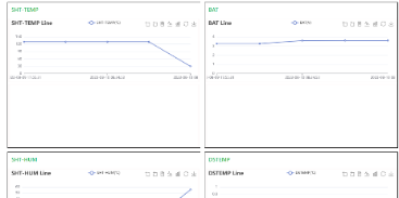
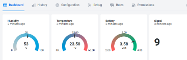
By configuring AIS01-CB on ThingsEye, you can intuitively see the trend of readings and obtain image data to see the real-time data.
The following shows how data can be uplinked to the ThingsEye platform via the UDP protocol
2.4.1 Create new devices in ThingsEye integration

Integration type select UDP:

Select JavaScript for Uplink data converter and Downlink data converter, and then fill in the code from the file.Uplink and downlink decoder codes.


Select JavaScript for Uplink data converter and Downlink data converter, and then fill in the code in the file.
1. Set the uplink port for the UDP protocol (we can help the user assign the port when shipping)
2.4.2 Import AIS01 rule chain library template
Rule chain library template file."ais01 _rule.json"

Select the device name you just created and save.

2.4.3 create a device profile
1. Select Device profiles
2. Click "+" to create a device profile
3. Create a name, select the rule chain template name "ais01-rule" just imported in Default rule chain
4. Click Add

2.4.4 Dashboard Configuration
Click Dashboards, click "+" and select Import dashboard to import the dashboard file.ais01 dashboard.josn

After importing, click edit mode.

Click allases, then click 2 to enter the edit.

After clicking save, the device will appear on the table.

2.4.5 Dashboard Contents
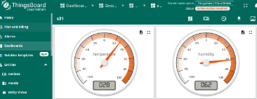
Click on the corresponding device and four modules will be displayed, namely, BAT, reading data, Image, and command issuing module.
You can enter 0B01 in the Update Multiple Attributes module and click Save, AIS01-CB will receive Image Polling Command in next data uplink and upload the image data.
There will be multiply packets uplink for the image and ThingsEye will re-built them and You will see the actual image in the Update Multiple Attributes module.

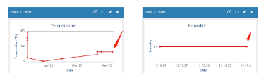
2.5 Node-Red Configuration
By configuring the AIS01-CB on the Node-RED, you can visualize trends in readings and acquire image data to view live dials.
The prerequisite is that the node has successfully uploaded the data.
2.5.1 Import file
Click on the upper right corner and click “import” to import the node red AIS01-CB file.

2.5.2 Edit the mqtt out node
The configuration to be modified is as follows:
1. Click on this module to enter the edit window
2. Enter the subscription subject of your node
3. Enter the edit window
4. Select the Security Edit window
5. Enter the MQTT username and password for the node.

The steps for modifying the content of these two modules are the same.

2.5.3 Edit the sqlite node

Select /home/lhr/root/data.db

Then click deploy

2.5.4 AIS01-CB Node Red UI
Click on the corresponding device and four modules will be displayed, namely, BAT data, reading data, image, and command issuing module.
You can enter 0B01 in the downlink module and click Save, AIS01-CB will receive the command and upload the image data after the next data upload.
You will see the actual image in the picture module.
(Note: If you need to use this function, TTN's Payload formatters need to be changed to https://github.com/dragino/dragino-end-node-decoder/blob/main/AIS01/AIS01_Thingseyes_Decoder.txt)

For more information about Node Red, please refer to Node-RED_Install and Use
3. Configure AIS01-CB
3.1 Configure Methods
AIS01-CB supports below configure method:
- AT Command via Bluetooth Connection (Recommended): BLE Configure Instruction.
- AT Command via UART Connection : See UART Connection.
- LoRaWAN Downlink. Instruction for different platforms: See IoT LoRaWAN Server section.
3.2 Commands special design for AIS01-CB
These commands only valid for AIS01-CB, as below:
3.2.1 Set Transmit Interval Time
Feature: Change LoRaWAN End Node Transmit Interval.
AT Command: AT+TDC
| Command Example | Function | Response |
|---|---|---|
| AT+TDC=? | Show current transmit Interval | 30000 |
| AT+TDC=60000 | Set Transmit Interval | OK |
Downlink Command: 0x01
Format: Command Code (0x01) followed by 3 bytes time value.
If the downlink payload=0100003C, it means set the END Node's Transmit Interval to 0x00003C=60(S), while type code is 01.
- Example 1: Downlink Payload: 0100001E // Set Transmit Interval (TDC) = 30 seconds
- Example 2: Downlink Payload: 0100003C // Set Transmit Interval (TDC) = 60 seconds
3.2.2 Set Interrupt Mode
Feature, Set Interrupt mode for GPIO_EXIT.
AT Command: AT+INTMOD1,AT+INTMOD2
| Command Example | Function | Response |
|---|---|---|
| AT+INTMOD1=? | Show current interrupt mode | 0 |
| AT+INTMOD1=2 | Set Transmit Interval | OK |
| AT+INTMOD2=2 | Set Transmit Interval 0. (Disable Interrupt), 1. (Trigger by rising and falling edge) 2. (Trigger by falling edge) 3. (Trigger by rising edge) | OK |
Downlink Command: 0x06
Format: Command Code (0x06) followed by 3 bytes.
This means that the interrupt mode of the end node is set to 0x000003=3 (rising edge trigger), and the type code is 06.
- Example 1: Downlink Payload: 06000000 ---> AT+INTMOD1=0
- Example 2: Downlink Payload: 06000003 ---> AT+INTMOD1=3
- Example 3: Downlink Payload: 06000102 ---> AT+INTMOD2=2
3.2.3 Setting up automatic image upload data
Feature: Automatically upload image data after each uplink packet
AT Command: AT+IMAGE
| Command Example | Function | Response |
| AT+IMAGE=1 | Enable automatic uploading of image data | 1 OK |
| AT+IMAGE=0 | Disable automatic uploading of image data | 0 |
Downlink Command: 0x0A
0X0A 01 // Same as AT+IMAGE=1
0x0A 00 // Same as AT+IMAGE=0
3.2.4 Example Query saved historical records
Feature:This command can be used to search the saved history, recording up to 32 groups of data, each group of historical data contains a maximum of 100 bytes.
AT Command: AT+CDP
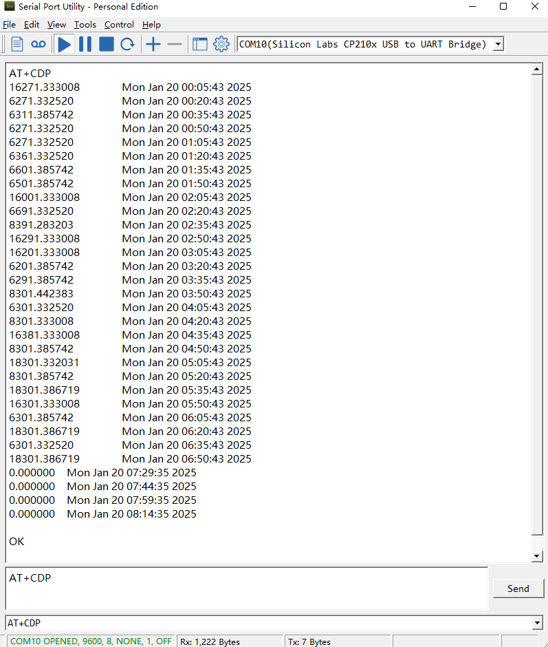
Downlink Command:
No downlink commands for feature
3.2.5 Uplink log query
Feature: This command can be used to query upstream logs of data packets.
AT Command: AT+GETLOG
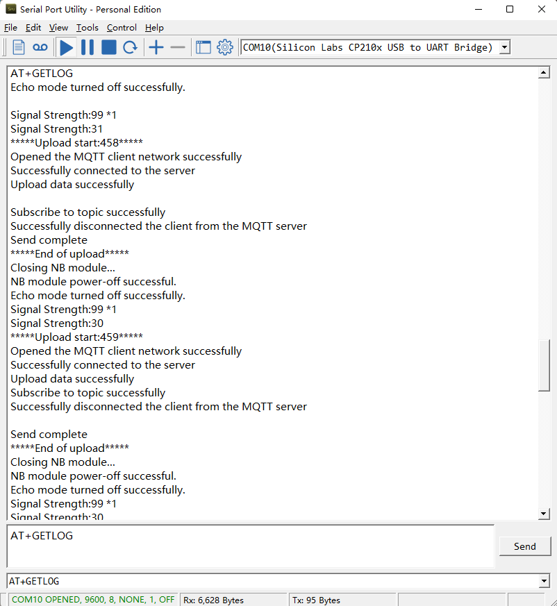
Downlink Command:
No downlink commands for feature
3.2.6 Set CoAP option
Feature: Set CoAP option, follow this link to set up the CoaP protocol.
AT command: AT+URI1~AT+URI8
AT+URI1=11,"i" // "i/" indicates that the endpoint supports observation mode. In -CB products, fixed setting AT+URI1=11,"i"
AT+URI2=11,"CoAP endpoint URl" // 11 is a fixed parameter.
Example: i/13a35fbe-9515-6e55-36e8-081fb6aacf86
AT+URI1=11,"i"
AT+URI2=11,"13a35fbe-9515-6e55-36e8-081fb6aacf86"
--> If multiple groups of CoAP endpoint urls:
AT+URI3=11,"i"
AT+URI4=11,"CoAP endpoint URl"
3.2.7 Set the downlink debugging mode(Since firmware v1.1.0)
Feature: Set the conversion between the standard version and 1T version downlinks.
AT command: AT+DOWNTE
| Command Example | Function/Parameters | Response/Explanation |
|---|---|---|
| AT+DOWNTE=? | Get current Settings | 0,0 (default) |
AT+DOWNTE=a,b | a: Set the conversion between the downlink of the standard version and 1T version | 0: Set the downlink of the standard version. |
| b: Enable/Disable downlink debugging | 0: Disable downlink debugging mode. |
Example:
- AT+DOWNTE=0,1 // Set to standard version downlink, and enable downlink debugging.
- AT+DOWNTE=1,1 // Set to 1T version downlink, and enable downlink debugging.
Downlink Command:
No downlink commands for feature
3.2.8 Domain name resolution settings(Since firmware v1.1.1)
Feature: Set static DNS resolution IP address.
AT command: AT+BKDNS
| Command Example | Function/Parameters | Response/Explanation |
|---|---|---|
AT+BKDNS=? | Get current Settings | 1,0,NULL (default) |
AT+BKDNS=a,b,c | a: Enable/Disable static DNS resolution. | 0: Disable static DNS resolution 1: Enable static DNS resolution. The ip address will be saved after the domain name is resolved, if the next domain name resolution fails, the last saved ip address will be used. |
| b: Meaningless. | Set to 0. | |
c: Set the IP address manually. | The format is the same as AT+SERVADDR. |
Example:
- AT+BKDNS=0,0,NULL //Disable static DNS resolution.
- AT+BKDNS=1,0,NULL // Enable static DNS resolution.
- AT+BKDNS=1,0,3.69.98.183,1883 //Enable static DNS resolution, if domain name resolution succeeds, the node uses the ip address successfully resolved and saves it to parameter c. If the domain name resolution fails, use the manually set ip address: 3.69.98.183 for communication.
Downlink Command:
No downlink commands for feature.
4. AT Commands Set
AT+<CMD>? : Help on <CMD>
AT+<CMD> : Run <CMD>
AT+<CMD>=<value> : Set the value
AT+<CMD>=? : Get the value
General Commands
AT+MODEL : Get module information
AT+CFGMOD : Working mode selection
AT+DEUI : Get or set the Device ID
AT+SERVADDR: Get or Set the Server address
AT+TDC : Get or set the application data transmission interval in s
AT+INTMOD : Get or Set the trigger interrupt mode (0:input,1:falling or rising,2:falling,3:rising)
AT+APN : Get or set the APN
AT+5VT : Get or Set extend the time of 5V power
AT+RXDL : Get or Set the receiving time
AT+GETSENSORVALUE : Returns the current sensor measurement
AT+DNSCFG : Get or Set DNS Server
AT+CSQTIME : Get or Set the time to join the network
AT+EXT : Get or Set Count value
AT+GDNS : Get or Set the DNS
AT+SLEEP : Get or Set the sleep mode
AT+IPTYPE : Set the IPv4 or IPv6
AT+QSW : Power on and power off BG95 module
AT+CLOCKLOG: Get or set SHT record time
AT+DOWNTE: Get or set the conversion between the standard version and 1T version downlinks
MQTT Management
AT+CLIENT : Get or Set the MQTT clientID
AT+UNAME : Get or Set the MQTT Username
AT+PWD : Get or Set the MQTT password
AT+PUBTOPIC: Get or set MQTT publishing topic
AT+SUBTOPIC: Get or set MQTT subscription topic
AT+MQOS : Set the QoS level of MQTT
AT+TLSMOD : Get or Set the TLS mode
COAP Management
AT+URI1: Get or set CoAP option 1
AT+URI2: Get or set CoAP option 2
AT+URI3: Get or set CoAP option 3
AT+URI4: Get or set CoAP option 4
AT+URI5: Get or set CoAP option 5
AT+URI6: Get or set CoAP option 6
AT+URI7: Get or set CoAP option 7
AT+URI8: Get or set CoAP option 8
GPS
AT+GNSST : Extend the time to turn on GNSS
AT+GPS : Turn off and on GPS
AT+GTDC : Get or set GPS positioning interval in units of h
Information
AT+FDR1 : Reset parameters to factory default values except for passwords
AT+FDR : Reset Parameters to Factory Default
AT+PWORD : Get or set the System password
AT+CFG : Print all settings
AT+CDP : Read or Clear cached data
AT+LDATA : Get the last upload data
AT+PRO : Get or Set usage agreement (1:COAP,2:UDP,3:MQTT,4:TCP)
AT+IMAGE : The next data packet will upload an image
AT+IOTMOD: Configure Network Category to be Searched for under LTE RAT
AT+QBAND: Get or set Frequency Band
ATZ : Trig a reset of the MCU
5. Clock logging
Sometimes when we deploy lots of end nodes in field. We want all sensors sample data at the same time, and upload these data together for analyze. In such case, we can use clock loging feature.
We can use this command to set the start time of data recording and the time interval to meet the requirements of the specific collection time of data.
- AT Command: AT+CLOCKLOG=a,b,c,d
a: 0: Disable Clock logging. 1: Enable Clock Logging
b: Specify First sampling start second: range (0 ~ 3599, 65535) // Note: If parameter b is set to 65535, the log period starts after the node accesses the network and sends packets.
c: Specify the sampling interval: range (0 ~ 255 minutes)
d:How many entries should be uplink on every TDC (max 32)
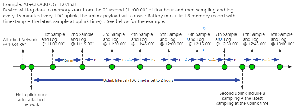
Example:
AT+CLOCKLOG=1,65535,1,5
After the node sends the first packet, data is recorded to the memory at intervals of 1 minute. For each TDC uplink, the uplink load will include: battery information + the last 5 memory records (payload + timestamp).
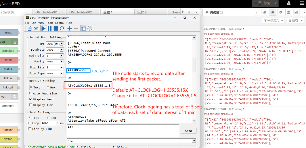
Note: Users need to synchronize the server time before configuring this command. If the server time is not synchronized before this command is configured, the command takes effect only after the node is reset.
6. Battery & Power Consumption
AIS01-CB use ER26500 + SPC1520 battery pack . See below link for detail information about the battery info and how to replace.
Battery Info & Power Consumption Analyze .
7. Case Study
7.1 Send Image to server to check different situation
Example 1: Users can use cameras to monitor whether the trash can is overflowing

Example 2: Users can use the camera to check whether the fire hydrant is in a safe and closed state.
8. OTA Firmware update
User can change firmware AIS01-CB to:
- Change Frequency band/ region.
- Update with new features.
- Fix bugs.
Firmware and changelog can be downloaded from : Firmware download link
Methods to Update Firmware:
- (Recommanded way) OTA firmware update via wireless: http://wiki.dragino.com/xwiki/bin/view/Main/Firmware%20OTA%20Update%20for%20Sensors/
- Update through UART TTL interface: Instruction.
9. FAQ
9.1 How can I access the BG95-NGFF AT Commands?
User can access to BG95-NGFF directly and send AT Commands.
9.2 General Manual for -CB , -CS models
Users can follow the instructions in this link to see how to configure to connect to different servers.
10. Order Info
Part Number: AIS01-CB-XX
XX:
- GE: General version ( Exclude SIM card)
- 1T: with 1NCE* 10 years 500MB SIM card and Pre-configure to ThingsEye server
1NCE SIM Card NB-IoT network coverage: Austria, Belgium, Bulgaria, Croatia, Czech Republic, Denmark, Finland, Germany, Great Britain, Greece, Hungary, Ireland, Italy, Latvia, Malta, Netherlands, Norway, Puerto Rico, Russia, Slovak , Republic, Slovenia, Spain, Sweden, Switzerland, Taiwan, USA, US Virgin Islands.
1NCE SIM Card LTE-M network coverage: Argentina, Austria, Australia, Belgium, Canada, Denmark, Estonia, Finland, France, Germany, Great Britain, Hungary, Ireland, Japan, Jersey, Korea, Repiblic of, Latvia, Luxembourg, Mexico, Netherlands, New Zealand, Norway, Poland, Puerto Rico, Romania, Spain, Sweden, Switzerland, Taiwan, USA, US Virgin Islands.
11. Packing Info
Package Includes:
- AIS01-CB NB-IoT/LTE-M AI Image End Node
- External antenna x 1
Dimension and weight:
- Device Size: cm
- Device Weight: g
- Package Size / pcs : cm
- Weight / pcs : g
12. Support
- Support is provided Monday to Friday, from 09:00 to 18:00 GMT+8. Due to different timezones we cannot offer live support. However, your questions will be answered as soon as possible in the before-mentioned schedule.
- Provide as much information as possible regarding your enquiry (product models, accurately describe your problem and steps to replicate it etc) and send a mail to support@dragino.cc
13. Appendix I: Field Installation Photo
Step1:
Find a water meter, install the AIS Sensor on the water meter fixture and install it on the water meter
The following is a comparison of before and after installation:
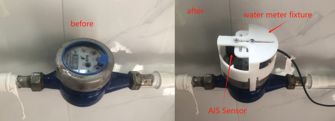
Step2:
Calibrate the AIS Sensor so that it can accurately read the water meter value.

Step3:
Choose a suitable location to place AIS01-CB,overall view

Get image data
When 0A 01 is sent on the TTN platform, the device will execute the command to send image data packet after sending the next data packet.

According to the method in 2.3.3.6, the combined data is converted into binary to obtain the following jpg image.
