PS-LB-NA LoRaWAN Analog Sensor User Manual
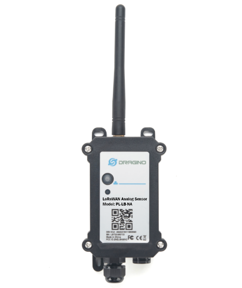
Table of Contents :
- 1. Introduction
- 2. Configure PS-LB-NA to connect to LoRaWAN network
- 3. Configure PS-LB-NA
- 4. Battery & Power Consumption
- 5. OTA firmware update
- 6. FAQ
- 7. Order Info
- 8. Packing Info
- 9. Support
1. Introduction
1.1 What is LoRaWAN Analog Sensor
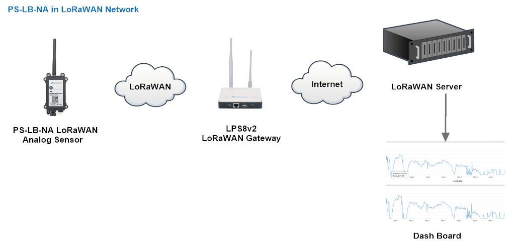
The Dragino PS-LB-NA is a LoRaWAN Analog Sensor for Internet of Things solution. PS-LB-NA has 5v and 12v output , 4~20mA, 0~30v input interface to power and get value from Analog Sensor. PS-LB-NA will convert the Analog Value to LoRaWAN wireless data and send to IoT platform via LoRaWAN gateway.
The LoRa wireless technology used in PS-LB-NA allows device to send data and reach extremely long ranges at low data-rates. It provides ultra-long range spread spectrum communication and high interference immunity whilst minimizing current consumption.
PS-LB-NA supports BLE configure and wireless OTA update which make user easy to use.
PS-LB-NA is powered by 8500mAh Li-SOCI2 battery, it is designed for long term use up to 5 years.
Each PS-LB-NA is pre-load with a set of unique keys for LoRaWAN registrations, register these keys to local LoRaWAN server and it will auto connect after power on.
1.2 Features
- LoRaWAN 1.0.3 Class A
- Ultra-low power consumption
- 1 x 0~20mA input , 1 x 0~30v input
- 5v and 12v output to power external sensor
- Monitor Battery Level
- Bands: CN470/EU433/KR920/US915/EU868/AS923/AU915/IN865
- Support Bluetooth v5.1 and LoRaWAN remote configure
- Support wireless OTA update firmware
- Uplink on periodically
- Downlink to change configure
- 8500mAh Battery for long term use
1.3 Specification
Micro Controller:
- MCU: 48Mhz ARM
- Flash: 256KB
- RAM: 64KB
Common DC Characteristics:
- Supply Voltage: 2.5v ~ 3.6v
- Operating Temperature: -40 ~ 85°C
LoRa Spec:
- Frequency Range, Band 1 (HF): 862 ~ 1020 Mhz
- Max +22 dBm constant RF output vs.
- RX sensitivity: down to -139 dBm.
- Excellent blocking immunity
Current Input (DC) Measuring :
- Range: 0 ~ 20mA
- Accuracy: 0.02mA
- Resolution: 0.001mA
Voltage Input Measuring:
- Range: 0 ~ 30v
- Accuracy: 0.02v
- Resolution: 0.001v
Battery:
- Li/SOCI2 un-chargeable battery
- Capacity: 8500mAh
- Self-Discharge: <1% / Year @ 25°C
- Max continuously current: 130mA
- Max boost current: 2A, 1 second
Power Consumption
- Sleep Mode: 5uA @ 3.3v
- LoRa Transmit Mode: 125mA @ 20dBm, 82mA @ 14dBm
1.4 Supported Extenal Sensors
PS-LB-NA can be used to power and connect to traditional industrial sensors and convert the sensor output signal to LoRaWAN signal. Below are some examples field as reference:
- Pressure Sensor: level sensors, level probes and pressure transmitters.
- Flow: flow of gases, liquids, or sludges.
- Level:
- Temperature/ Humidity: temperature probes, such as RTD temperature probes, thermocouples.
- Liquid analysis: pH values, redox potential, electrolytic conductivity, ammonia, dissolved oxygen, turbidity, chlorine, and much more
Key point for external sensor:
- Can be powered by 5v or 12v. Require Current < 1A.
- Sensor has output within range: 4~20mA or 0~30v.
- Sensor will be power off and power on after deployment. and After power on, it can provide valid output within several seconds.
1.5 Sleep mode and working mode
Deep Sleep Mode: Sensor doesn't have any LoRaWAN activate. This mode is used for storage and shipping to save battery life.
Working Mode: In this mode, Sensor will work as LoRaWAN Sensor to Join LoRaWAN network and send out sensor data to server. Between each sampling/tx/rx periodically, sensor will be in IDLE mode), in IDLE mode, sensor has the same power consumption as Deep Sleep mode.
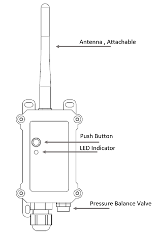
1.6 Button & LEDs
| Behavior on ACT | Function | Action |
|---|---|---|
| Pressing ACT between 1s < time < 3s | Send an uplink | If sensor is already Joined to LoRaWAN network, sensor will send an uplink packet, blue led will blink once. |
| Pressing ACT for more than 3s | Active Device | Green led will fast blink 5 times, device will enter OTA mode for 3 seconds. And then start to JOIN LoRaWAN network. |
| Fast press ACT 5 times. | Deactivate Device | Red led will solid on for 5 seconds. Means PS-LB-NA is in Deep Sleep Mode. |
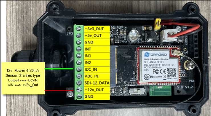
1.7 Pin Mapping
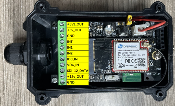
- +3v3_OUT: Controllable 3.3v output, Actually voltage level same as Battery, 2.6v ~ 3.6v
- +5v_OUT: Controllable 5.0v output
- GND: GND
- INT: Interrupt Pin
- IN1 & IN2: Digital IN1 and Digital IN2
- IDC_IN: 4~20mA current input pin
- VDC_IN: 0~30v sensor voltage input pin
- SDI-12_DATA: No used
- +12v_OUT: Controllable 12v output
- GND: GND
1.8 BLE connection
PS-LB-NA support BLE remote configure.
BLE can be used to configure the parameter of sensor or see the console output from sensor. BLE will be only activate on below case:
- Press button to send an uplink
- Press button to active device.
- Device Power on or reset.
If there is no activity connection on BLE in 60 seconds, sensor will shut down BLE module to enter low power mode.
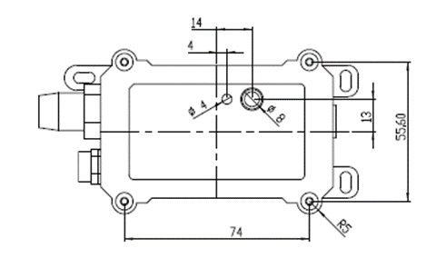
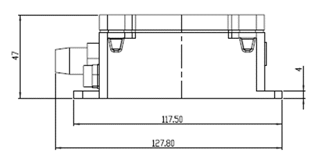
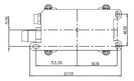
1.9 Mechanical
2. Configure PS-LB-NA to connect to LoRaWAN network
2.1 How it works
The PS-LB-NA is configured as LoRaWAN OTAA Class A mode by default. It has OTAA keys to join LoRaWAN network. To connect a local LoRaWAN network, you need to input the OTAA keys in the LoRaWAN IoT server and activate the PS-LB-NA. It will automatically join the network via OTAA and start to send the sensor value. The default uplink interval is 20 minutes.
2.2 Quick guide to connect to LoRaWAN server (OTAA)
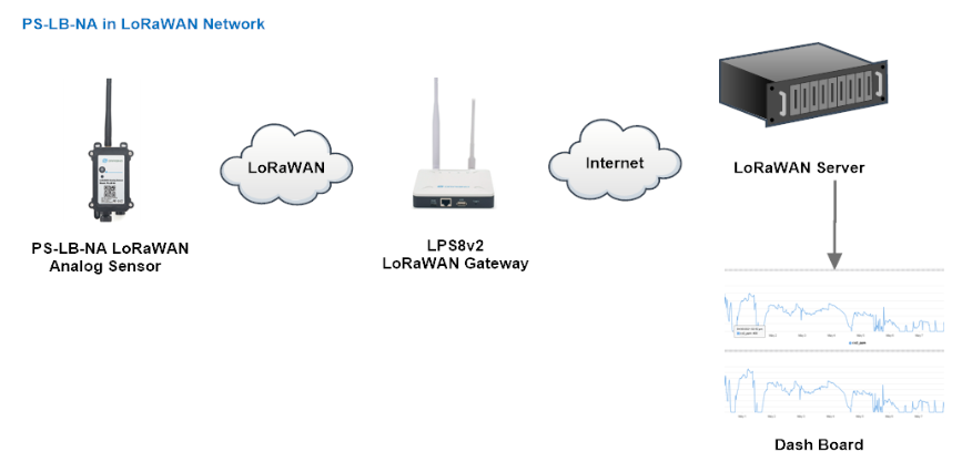
Following is an example for how to join the TTN v3 LoRaWAN Network. Below is the network structure; we use the LPS8v2 as a LoRaWAN gateway in this example.
The LPS8V2 is already set to connected to TTN network , so what we need to now is configure the TTN server.
Step 1: Create a device in TTN with the OTAA keys from PS-LB-NA.
Each PS-LB-NA is shipped with a sticker with the default device EUI as below:
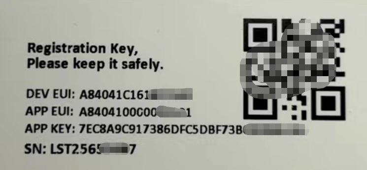
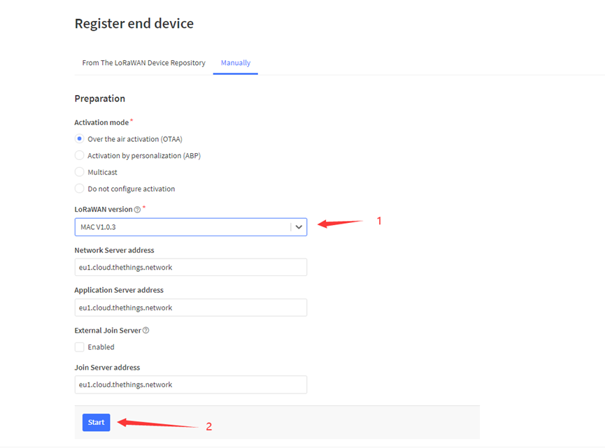
You can enter this key in the LoRaWAN Server portal. Below is TTN screen shot:
Register the device
Add APP EUI and DEV EUI
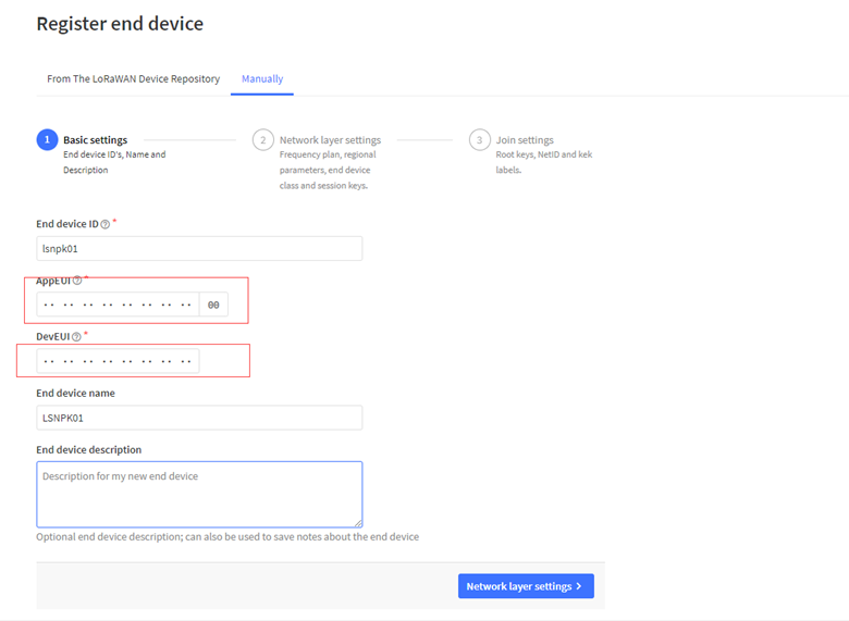
Add APP EUI in the application
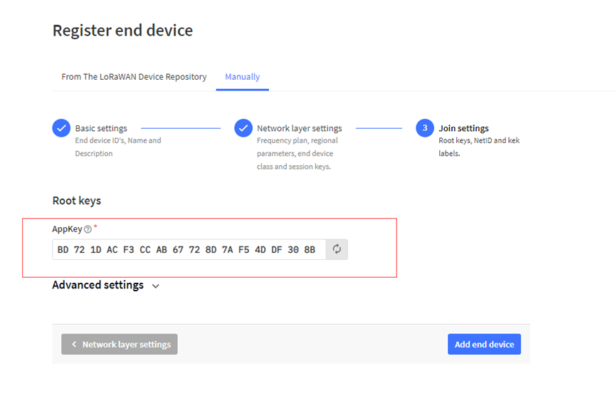
Add APP KEY
Step 2: Activate on PS-LB-NA
Press the button for 5 seconds to activate the PS-LB-NA.
Green led will fast blink 5 times, device will enter OTA mode for 3 seconds. And then start to JOIN LoRaWAN network. Green led will solidly turn on for 5 seconds after joined in network.
After join success, it will start to upload messages to TTN and you can see the messages in the panel.
2.3 Uplink Payload
2.3.1 Device Status, FPORT=5
Include device configure status. Once PS-LB-NA Joined the network, it will uplink this message to the server.
Users can also use the downlink command(0x26 01) to ask PS-LB-NA to resend this uplink.
| Device Status (FPORT=5) | |||||
| Size (bytes) | 1 | 2 | 1 | 1 | 2 |
| Value | Sensor Model | Firmware Version | Frequency Band | Sub-band | BAT |
Example parse in TTNv3
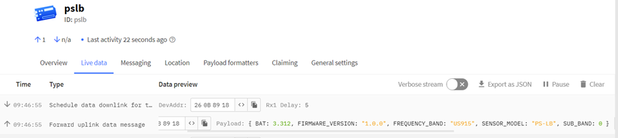
Sensor Model: For PS-LB-NA, this value is 0x16
Firmware Version: 0x0100, Means: v1.0.0 version
Frequency Band:
0x01: EU868
0x02: US915
0x03: IN865
0x04: AU915
0x05: KZ865
0x06: RU864
0x07: AS923
0x08: AS923-1
0x09: AS923-2
0x0a: AS923-3
0x0b: CN470
0x0c: EU433
0x0d: KR920
0x0e: MA869
Sub-Band:
AU915 and US915:value 0x00 ~ 0x08
CN470: value 0x0B ~ 0x0C
Other Bands: Always 0x00
Battery Info:
Check the battery voltage.
Ex1: 0x0B45 = 2885mV
Ex2: 0x0B49 = 2889mV
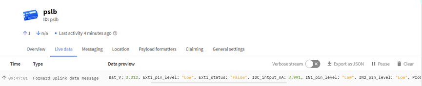
2.3.2 Sensor value, FPORT=2
Uplink payload includes in total 9 bytes.
Size(bytes) | 2 | 2 | 2 | 2 | 1 |
| Value | BAT | Probe Model | 0 ~ 20mA value | 0 ~ 30v value | IN1 &IN2 Interrupt flag |
2.3.3 Battery Info
Check the battery voltage for PS-LB-NA.
Ex1: 0x0B45 = 2885mV
Ex2: 0x0B49 = 2889mV
2.3.4 Probe Model
PS-LB-NA might connect to different kind of probes, 4~20mA represent the full scale of the measuring range. So a 12mA output means different meaning for different probe.
For example.
| Probe Type | 4~20mA scale for this probe | Example: 12mA actually meaning for this probe |
| PH Combination Electrodes | 0 ~ 14 pH | PH Value: 7 |
| Water Pressure Sensor | 0~5 meters | 2.5 meters pure water |
| Pressure transmitter probe | 0~1MPa | 0.5MPa air / gas or water pressure |
User can set different probe model for above probes. So IoT server is able to se identical how it should parse the 4~20mA or 0~30v sensor value and get the correct value.
2.3.5 0~20mA value (IDC_IN)
Payload Example:
27AE(H) = 10158 (D)/1000 = 10.158mA.
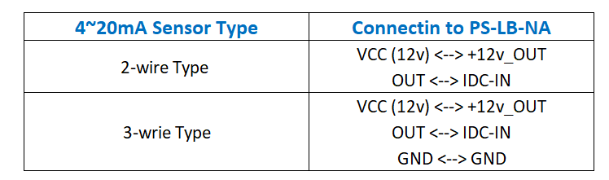
Connect to a 2 wire 4~20mA sensor.
2.3.6 0~30V value ( pin VDC_IN)
Measure the voltage value. The range is 0 to 30V.
Example:
138E(H) = 5006(D)/1000= 5.006V
2.3.7 IN1&IN2&INT pin
IN1 and IN2 are used as digital input pins.
Example:
09 (H): (0x09&0x08)>>3=1 IN1 pin is high level.
09 (H): (0x09&0x04)>>2=0 IN2 pin is low level.
This data field shows if this packet is generated by Interrupt Pin or not. Click here for the hardware and software set up. Note: The Internet Pin is a separate pin in the screw terminal.
Example:
09 (H): (0x09&0x02)>>1=1 The level of the interrupt pin.
09 (H): 0x09&0x01=1 0x00: Normal uplink packet.
0x01: Interrupt Uplink Packet.
2.3.8 Sensor value, FPORT=7
Size(bytes) | 2 | n |
| Value | BAT | Voltage value, each 2 bytes is a set of voltage values. |
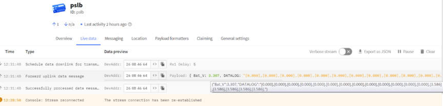
Multiple sets of data collected are displayed in this form:
[voltage value1], [voltage value2], [voltage value3],…[voltage value n/2]
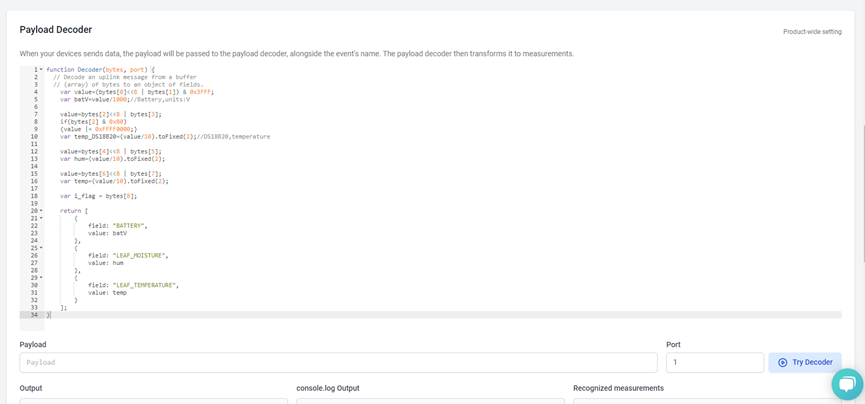
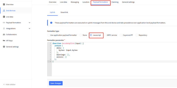
2.3.9 Decode payload in The Things Network
While using TTN network, you can add the payload format to decode the payload.
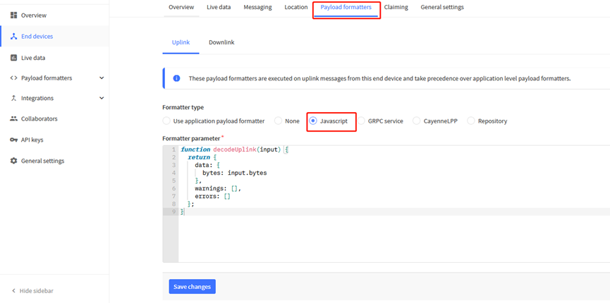
PS-LB-NA TTN Payload Decoder: https://github.com/dragino/dragino-end-node-decoder
2.4 Uplink Interval
The PS-LB-NA by default uplink the sensor data every 20 minutes. User can change this interval by AT Command or LoRaWAN Downlink Command. See this link: http://wiki.dragino.com/xwiki/bin/view/Main/End%20Device%20AT%20Commands%20and%20Downlink%20Command/#H4.1ChangeUplinkInterval
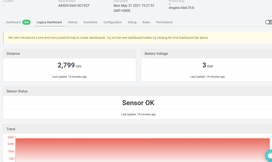
2.5 Show Data in DataCake IoT Server
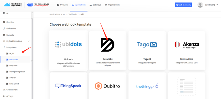
DATACAKE provides a human friendly interface to show the sensor data, once we have data in TTN, we can use DATACAKE to connect to TTN and see the data in DATACAKE. Below are the steps:
Step 1: Be sure that your device is programmed and properly connected to the network at this time.
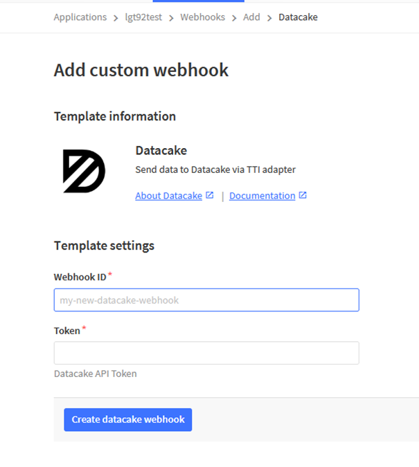
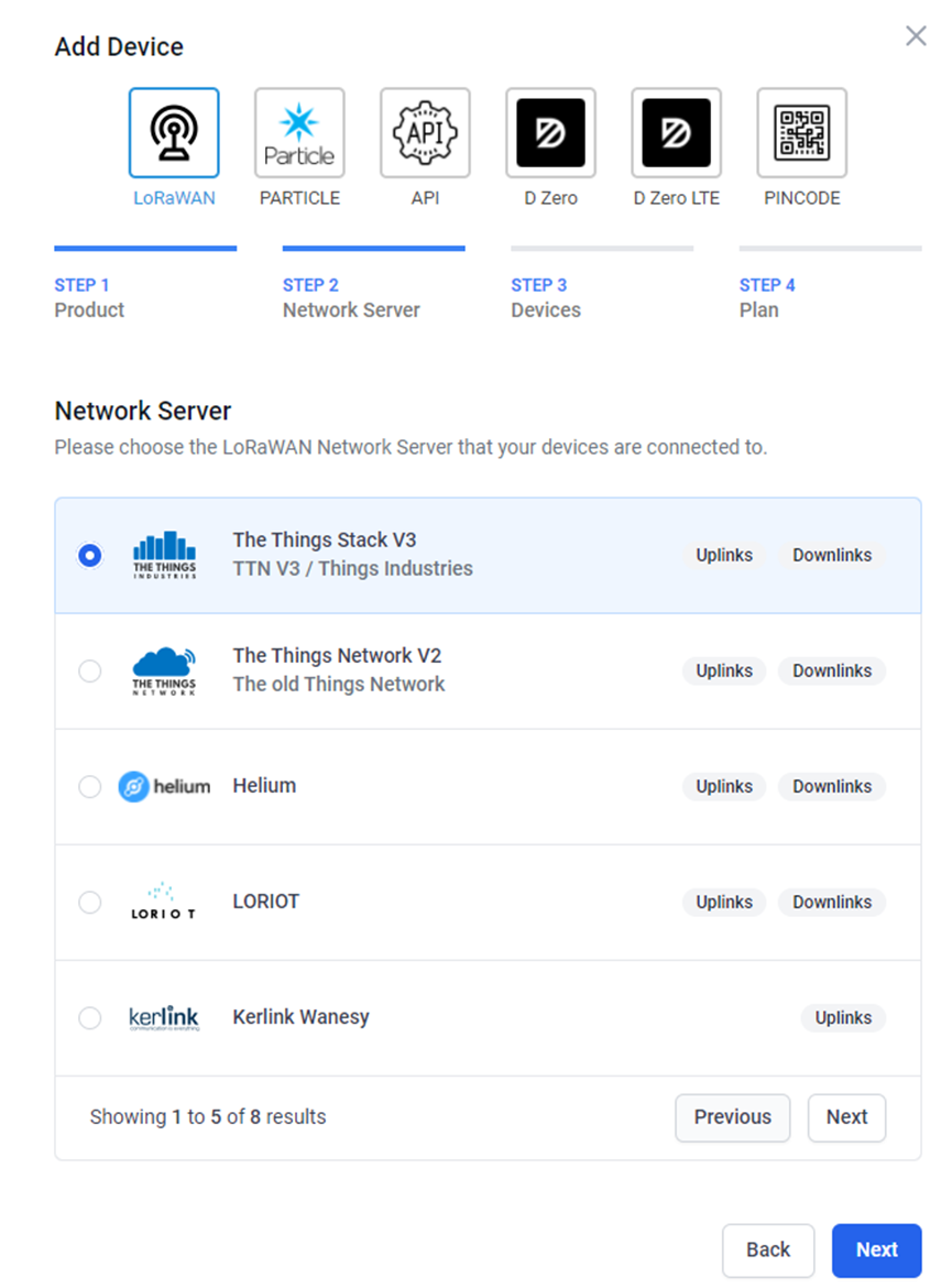
Step 2: To configure the Application to forward data to DATACAKE you will need to add integration. To add the DATACAKE integration, perform the following steps:
Step 3: Create an account or log in Datacake.
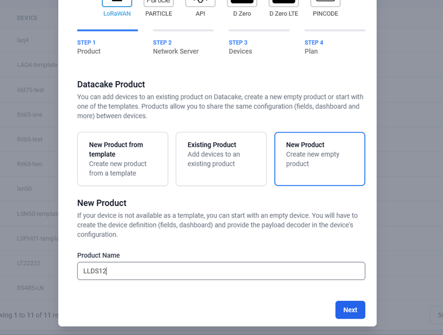
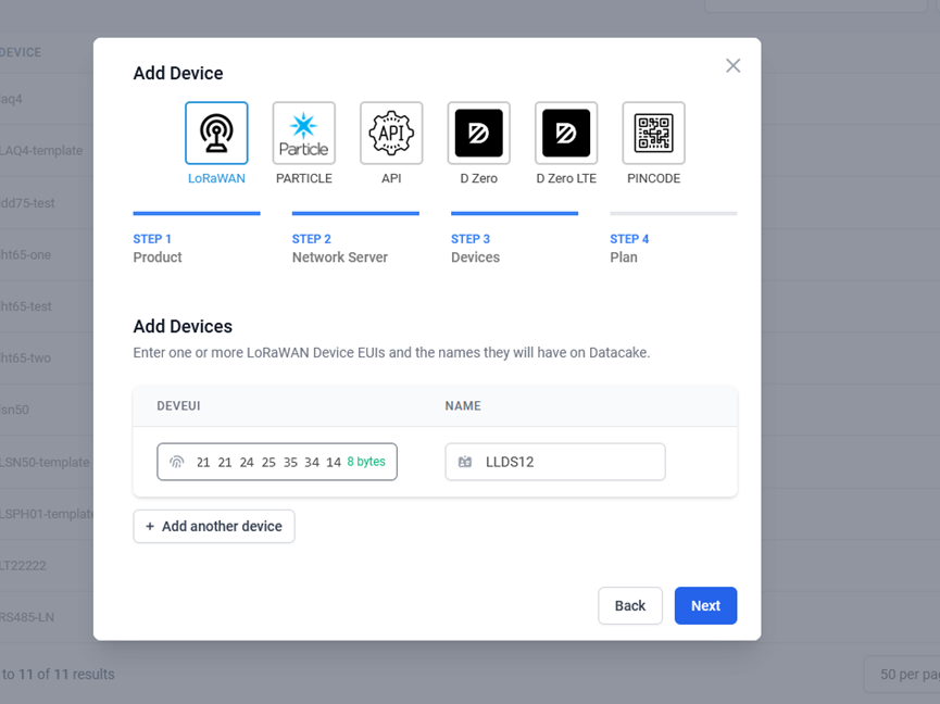
Step 4: Create PS-LB-NA product.
Step 5: add payload decode
After added, the sensor data arrive TTN, it will also arrive and show in Datacake.
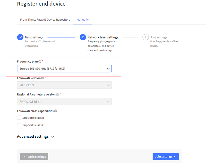
2.6 Frequency Plans
The PS-LB-NA uses OTAA mode and below frequency plans by default. Each frequency band use different firmware, user update the firmware to the corresponding band for their country.
http://wiki.dragino.com/xwiki/bin/view/Main/End%20Device%20Frequency%20Band/
2.7 Datalog Feature (Since V1.1)
When a user wants to retrieve sensor value, he can send a poll command from the IoT platform to ask the sensor to send value in the required time slot.
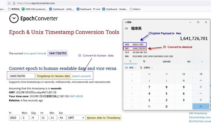
2.7.1 Unix TimeStamp
CPL01 uses Unix TimeStamp format based on
Users can get this time from the link: https://www.epochconverter.com/ :
Below is the converter example:
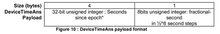
2.7.2 Set Device Time
There are two ways to set the device's time:
1. Through LoRaWAN MAC Command (Default settings)
Users need to set SYNCMOD=1 to enable sync time via the MAC command.
Once CPL01 Joined the LoRaWAN network, it will send the MAC command (DeviceTimeReq) and the server will reply with (DeviceTimeAns) to send the current time to CPL01. If CPL01 fails to get the time from the server, CPL01 will use the internal time and wait for the next time request [via Device Status (FPORT=5)].
Note: LoRaWAN Server needs to support LoRaWAN v1.0.3(MAC v1.0.3) or higher to support this MAC command feature.
2. Manually Set Time
Users need to set SYNCMOD=0 to manual time, otherwise, the user set time will be overwritten by the time set by the server.
2.7.3 Poll sensor value
Users can poll sensor values based on timestamps. Below is the downlink command.
| Downlink Command to poll Open/Close status (0x31) | |||
|---|---|---|---|
| 1byte | 4bytes | 4bytes | 1byte |
| 31 | Timestamp start | Timestamp end | Uplink Interval |
Timestamp start and Timestamp end-use Unix TimeStamp format as mentioned above. Devices will reply with all data logs during this period, using the uplink interval.
For example, downlink command
Is to check 2021/11/12 12:00:00 to 2021/11/12 15:00:00's data
Uplink Internal =5s,means CPL01 will send one packet every 5s. range 5~255s.
2.7.4 Decoder in TTN V3
Please check the decoder from this link: https://github.com/dragino/dragino-end-node-decoder
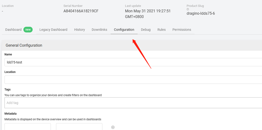
3. Configure PS-LB-NA
3.1 Configure Methods:
PS-LB-NA supports below configure method:
- AT Command via Bluetooth Connection (Recommand Way): BLE Configure Instruction.
- AT Command via UART Connection : See FAQ.
- LoRaWAN Downlink. Instruction for different platforms: See IoT LoRaWAN Server section.
3.2 General Commands
These commands are to configure:
- General system settings like: uplink interval.
- LoRaWAN protocol & radio related command.
They are same for all Dragino Devices which support DLWS-005 LoRaWAN Stack. These commands can be found on the wiki:
http://wiki.dragino.com/xwiki/bin/view/Main/End%20Device%20AT%20Commands%20and%20Downlink%20Command/
3.3 Commands special design for PS-LB-NA
These commands only valid for PS-LB-NA, as below:
3.3.1 Set Transmit Interval Time
Feature: Change LoRaWAN End Node Transmit Interval.
AT Command: AT+TDC
| Command Example | Function | Response |
|---|---|---|
| AT+TDC=? | Show current transmit Interval | 30000 |
| AT+TDC=60000 | Set Transmit Interval | OK |
Downlink Command: 0x01
Format: Command Code (0x01) followed by 3 bytes time value.
If the downlink payload=0100003C, it means set the END Node's Transmit Interval to 0x00003C=60(S), while type code is 01.
- Example 1: Downlink Payload: 0100001E // Set Transmit Interval (TDC) = 30 seconds
- Example 2: Downlink Payload: 0100003C // Set Transmit Interval (TDC) = 60 seconds
3.3.2 Set Interrupt Mode
Feature, Set Interrupt mode for GPIO_EXIT.
AT Command: AT+INTMOD
| Command Example | Function | Response |
|---|---|---|
| AT+INTMOD=? | Show current interrupt mode | 0 |
| AT+INTMOD=2 | Set Transmit Interval | OK |
Downlink Command: 0x06
Format: Command Code (0x06) followed by 3 bytes.
This means that the interrupt mode of the end node is set to 0x000003=3 (rising edge trigger), and the type code is 06.
- Example 1: Downlink Payload: 06000000 // Turn off interrupt mode
- Example 2: Downlink Payload: 06000003 // Set the interrupt mode to rising edge trigger
3.3.3 Set Power Output Duration
Control the output duration 3V3 , 5V or 12V. Before each sampling, device will
1. first enable the power output to external sensor,
2. keep it on as per duration, read sensor value and construct uplink payload
3. final, close the power output.
AT Command: AT+3V3T
| Command Example | Function | Response |
|---|---|---|
| AT+3V3T=? | Show 3V3 open time. | 0 |
| AT+3V3T=0 | Normally open 3V3 power supply. | OK |
| AT+3V3T=1000 | Close after a delay of 1000 milliseconds. | OK |
| AT+3V3T=65535 | Normally closed 3V3 power supply. | OK |
AT Command: AT+5VT
| Command Example | Function | Response |
|---|---|---|
| AT+5VT=? | Show 5V open time. | 0 |
| AT+5VT=0 | Normally closed 5V power supply. | OK |
| AT+5VT=1000 | Close after a delay of 1000 milliseconds. | OK |
| AT+5VT=65535 | Normally open 5V power supply. | OK |
AT Command: AT+12VT
| Command Example | Function | Response |
|---|---|---|
| AT+12VT=? | Show 12V open time. | 0 |
| AT+12VT=0 | Normally closed 12V power supply. | OK |
| AT+12VT=500 | Close after a delay of 500 milliseconds. | OK |
Downlink Command: 0x07
Format: Command Code (0x07) followed by 3 bytes.
The first byte is which power, the second and third bytes are the time to turn on.
- Example 1: Downlink Payload: 070101F4 ---> AT+3V3T=500
- Example 2: Downlink Payload: 0701FFFF ---> AT+3V3T=65535
- Example 3: Downlink Payload: 070203E8 ---> AT+5VT=1000
- Example 4: Downlink Payload: 07020000 ---> AT+5VT=0
- Example 5: Downlink Payload: 070301F4 ---> AT+12VT=500
- Example 6: Downlink Payload: 07030000 ---> AT+12VT=0
3.3.4 Set the Probe Model
Users need to configure this parameter according to the type of external probe. In this way, the server can decode according to this value, and convert the current value output by the sensor into water depth or pressure value.
AT Command: AT +PROBE
AT+PROBE=aabb
When aa=00, it is the water depth mode, and the current is converted into the water depth value; bb is the probe at a depth of several meters.
When aa=01, it is the pressure mode, which converts the current into a pressure value;
bb represents which type of pressure sensor it is.
(A->01,B->02,C->03,D->04,E->05,F->06,G->07,H->08,I->09,J->0A,K->0B,L->0C)
| Command Example | Function | Response |
| AT +PROBE =? | Get or Set the probe model. | 0 OK |
| AT +PROBE =0003 | Set water depth sensor mode, 3m type. | OK |
AT +PROBE =000A
| Set water depth sensor mode, 10m type. | OK |
| AT +PROBE =0101 | Set pressure transmitters mode, first type(A). | OK |
| AT +PROBE =0000 | Initial state, no settings. | OK |
Downlink Command: 0x08
Format: Command Code (0x08) followed by 2 bytes.
- Example 1: Downlink Payload: 080003 ---> AT+PROBE=0003
- Example 2: Downlink Payload: 080101 ---> AT+PROBE=0101
3.3.5 Multiple VDC /IDC collections in one uplink
Added AT+STDC command to collect the voltage of VDC_INPUT/IDC_INPUT multiple times and upload it at one time.
AT Command: AT +STDC
AT+STDC=aa,bb,bb
aa:
0: means disable this function and use TDC to send packets.
1: means that the function is enabled to send packets by collecting VDC data for multiple times
2: means that the function is enabled to send packets by collecting IDC data for multiple times
bb: Each collection interval (s), the value is 1~65535
cc: the number of collection times, the value is 1~120
| Command Example | Function | Response |
| AT+STDC=? | Get the mode of multiple acquisitions and one uplink. | 1,10,18 OK |
| AT+STDC=1,10,18 | Set the mode of multiple acquisitions and one uplink, collect once every 10 seconds, and report after 18 times. | Attention:Take effect after ATZ OK |
| AT+STDC=0, 0,0 | Use the TDC interval to send packets.(default)
| Attention:Take effect after ATZ OK |
Downlink Command: 0xAE
Format: Command Code (0xAE) followed by 4 bytes.
- Example 1: Downlink Payload: AE 01 02 58 12 ---> AT+STDC=1,600,18
4. Battery & Power Consumption
PS-LB-NA uses ER26500 + SPC1520 battery pack. See below link for detail information about the battery info and how to replace.
Battery Info & Power Consumption Analyze .
5. OTA firmware update
User can change firmware S31x-LB to:
- Change Frequency band/ region.
- Update with new features.
- Fix bugs.
Firmware and changelog can be downloaded from : Firmware download link
Methods to Update Firmware:
- (Recommanded way) OTA firmware update via wireless: http://wiki.dragino.com/xwiki/bin/view/Main/Firmware%20OTA%20Update%20for%20Sensors/
- Update through UART TTL interface. Instruction.
6. FAQ
6.1 How to use PS-LB-Ix with liquid other than water?
Calculated according to the ratio of the density of the measured liquid to the density of water, and add their ratio in the decoding
Example: Use gasoline with a density of 0.70g/cm^3
Adding to this part of the decoding divides it by 0.7 and puts a parenthesis around the equation
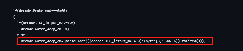
Change:
if(decode.Probe_mod===0x00)
{
if(decode.IDC_intput_mA<=4.0)
decode.Water_deep_cm= 0;
else
decode.Water_deep_cm= parseFloat((% style="color:red" %)(((decode.IDC_intput_mA-4.0)*(bytes[3]*100/16)/0.7)).toFixed(3));
}
7. Order Info
Part Number: PS-LB-NA-XX-YY
XX: The default frequency band
- AS923: LoRaWAN AS923 band
- AU915: LoRaWAN AU915 band
- EU433: LoRaWAN EU433 band
- EU868: LoRaWAN EU868 band
- KR920: LoRaWAN KR920 band
- US915: LoRaWAN US915 band
- IN865: LoRaWAN IN865 band
- CN470: LoRaWAN CN470 band
YY: The grand connector hole size
- M12: M12 hole
- M16: M16 hole
- M20: M20 hole
8. Packing Info
Package Includes:
- PS-LB-NA LoRaWAN Analog Sensor
Dimension and weight:
- Device Size: cm
- Device Weight: g
- Package Size / pcs : cm
- Weight / pcs : g
9. Support
- Support is provided Monday to Friday, from 09:00 to 18:00 GMT+8. Due to different timezones we cannot offer live support. However, your questions will be answered as soon as possible in the before-mentioned schedule.
- Provide as much information as possible regarding your enquiry (product models, accurately describe your problem and steps to replicate it etc) and send a mail to support@dragino.com