Table of Contents:
1. Introduction
1.1 What is LMDS200 Microwave Radar DistanceSensor
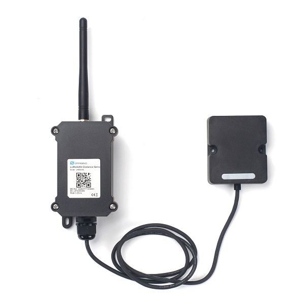
The Dragino LMDS200 is a LoRaWAN Microwave Radar distance sensor. It uses 24Ghz Microwave to detect the distance between sensor and different objects. Compare vs ultrasonic or Lidar measurement method, Microwave Radar is more reliable for condensation / dusty environment. It can sense correct distance even there is water or thick dust on top of the sensor.
The LMDS200 can be applied to scenarios such as horizontal distance measurement, parking management system, object proximity and presence detection, intelligent trash can management system, robot obstacle avoidance, automatic control, sewer, etc.
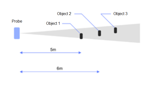
LMDS200 can measure two distances: the closest object and next object behind the closest one.
LMDS200 supports Alarm Feature, user can set the LMDS200 to uplink data in a short interval when the distance is out of configured range.
The LoRa wireless technology used in LMDS200 allows device to send data and reach extremely long ranges at low data-rates. It provides ultra-long range spread spectrum communication and high interference immunity whilst minimizing current consumption.
LMDS200 is powered by 8500mAh Li-SOCI2 battery, it is designed for long term use up to 5 years.
Each LMDS200 is pre-load with a set of unique keys for LoRaWAN registrations, register these keys to local LoRaWAN server and it will auto connect after power on.
*Battery life depends on how often to send data, please see battery analyzer.

1.2 Features
- LoRaWAN 1.0.3 Class A
- Ultra-low power consumption
- Microwave Radar for distance detection
- Short uplink interval for Distance Alarm
- Monitor Battery Level
- Bands: CN470/EU433/KR920/US915/EU868/AS923/AU915/IN865
- AT Commands to change parameters
- Uplink on periodically
- Downlink to change configure
- 8500mAh Battery for long term use
- Wall Mountable
- Outdoor Use
1.3 Radar probe specification
- Measuring Method: FMCW
- Frequency: 24.000 ~ 24.500 GHz
- Measurement output power: 6dBm
- Measure range: 0.5 ~ 20m
- Accuracy: ±0.1m
- Resolution: 0.01m
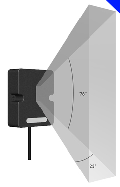
- Horizontal Angel: 78°
- Vertical Angel: 23°
1.4 Storage & Operation Temperature
-20°C to +85°C
1.5 Applications
- Horizontal distance measurement
- Liquid level measurement
- Parking management system
- Object proximity and presence detection
- Intelligent trash can management system
- Robot obstacle avoidance
- Automatic control
- Sewer
- Bottom water level monitoring
1.6 Installation
Sensor measure direction and angle is as below. When install the sensor, please make sure the sensor direct to object.
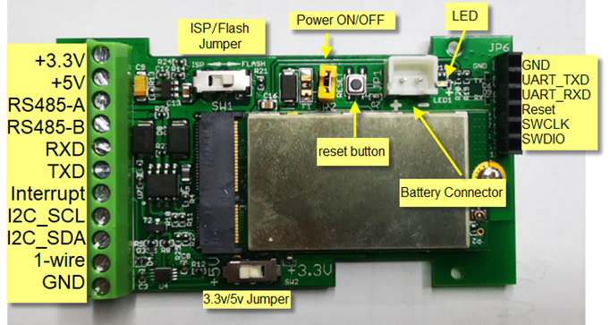
1.7 Pin mapping and power on
2. Operation Mode
2.1 How it works
Each LMDS200 is shipped with a worldwide unique set of OTAA keys. To use LMDS200 in a LoRaWAN network, user needs to input the OTAA keys in the LoRaWAN network server. So LMDS200 can join the LoRaWAN network and start to transmit sensor data.
2.2 Example to use for LoRaWAN network
Following is an example for how to join the TTN v3 LoRaWAN Network. Below is the network structure; we use the LG308 as a LoRaWAN gateway in this example.
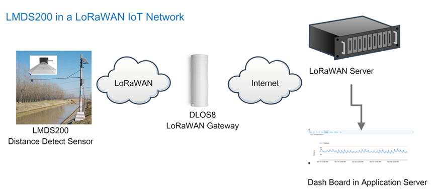
- In this user case, the LMDS200 is installed on top of river to detect the water level and send the level info to the LoRaWAN server. The LMDS200 will uplink different types of messages to the LoRaWAN server. See Uplink payload for detail.
Assume the LoRaWAN Gateway DLOS8 is already set to connect to the TTN V3 network . We need to add the LMDS200 device in TTN V3:
Step 1: Create a device in TTN with the OTAA keys from LMDS200.
Each LMDS200 is shipped with a sticker with the default device keys, user can find this sticker in the box. it looks like below.
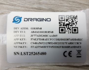
Users can enter these keys in the LoRaWAN Server portal. Below is the TTN V3 screenshot:
Add APP EUI in the application.
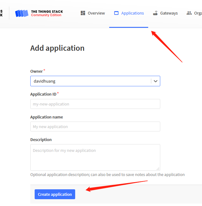
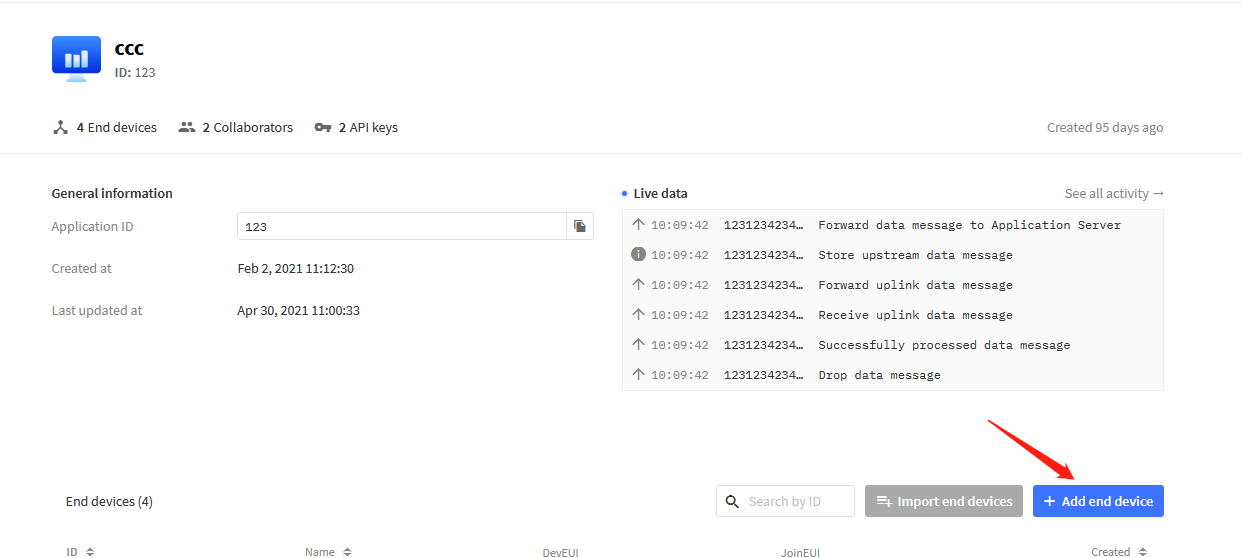
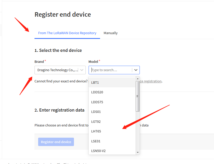
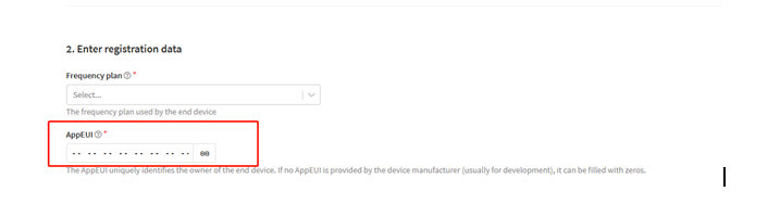
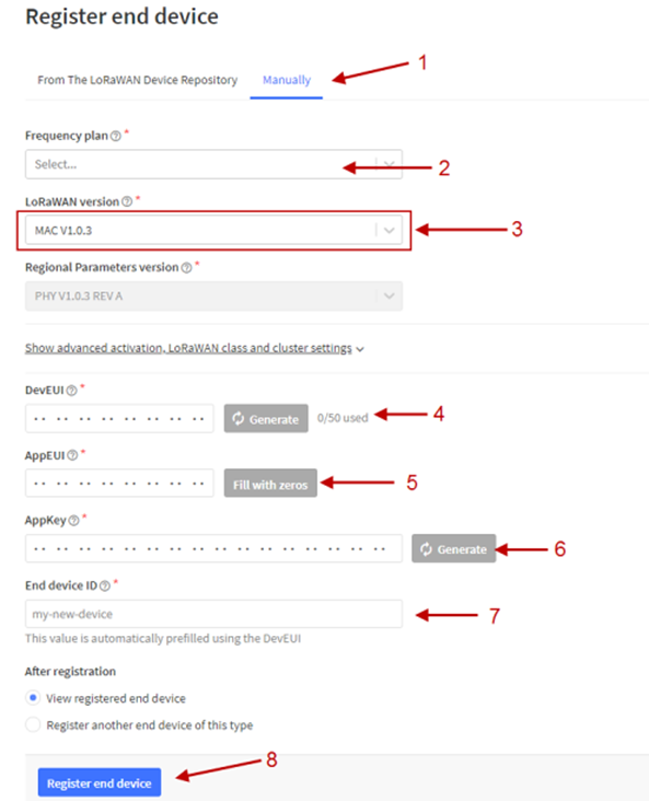
You can also choose to create the device manually.
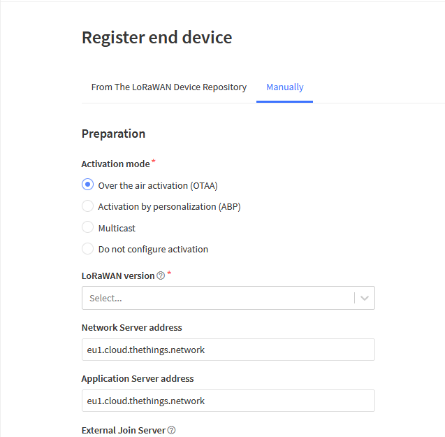
Add APP KEY and DEV EUI
Step 2: Power on LMDS200
Put a Jumper on JP2 to power on the device. ( The Switch must be in FLASH position).
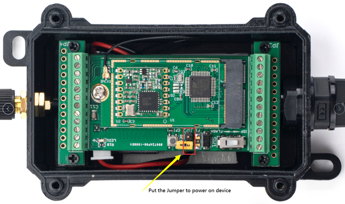
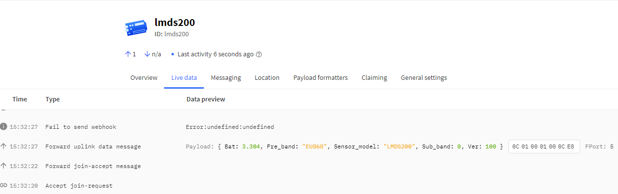
Put the jumper to power on LMDS200 and it will auto-join to the TTN V3 network. After join success, it will start to upload sensor data to TTN V3 and the user can see it in the panel.
2.3 Uplink Payload
Uplink payloads have two types:
- Distance Value: Use FPORT=2
- Other control commands: Use other FPORT fields.
The application server should parse the correct value based on FPORT settings.
2.3.1 Device Status, FPORT=5
Include device configure status. Once LMDS200 Joined the network, it will uplink this message to the server.
Users can also use the downlink command (0x26 01) to ask LMDS200 to resend Device Status.
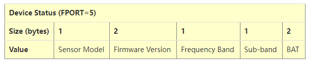
- Sensor Model: For LMDS200, this value is 0x0C
- Firmware Version: 0x0100, Means: v1.0.0 version
- Frequency Band:
*0x01: EU868
*0x02: US915
*0x03: IN865
*0x04: AU915
*0x05: KZ865
*0x06: RU864
*0x07: AS923
*0x08: AS923-1
*0x09: AS923-2
*0x0a: AS923-3
*0x0b: CN470
*0x0c: EU433
*0x0d: KR920
*0x0e: MA869
- Sub-Band:
- AU915 and US915:value 0x00 ~ 0x08
- CN470: value 0x0B ~ 0x0C
- Other Bands: Always 0x00
- Battery Info:
Check the battery voltage.
Ex1: 0x0B45 = 2885mV
Ex2: 0x0B49 = 2889mV
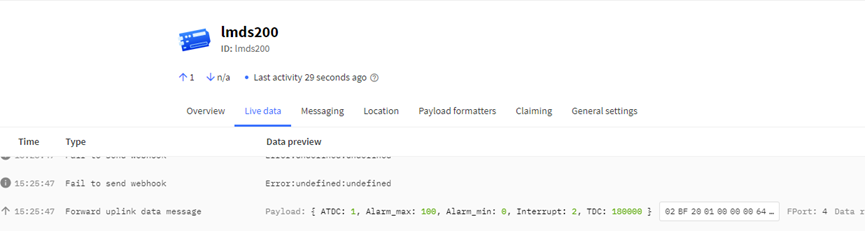
2.3.2 Sensor Configuration, FPORT=4
LMDS200 will only send this command after getting the downlink command (0x26 02) from the server.
| Sensor Configuration FPORT=4 | ||||
| Size (bytes) | 3 | 1 | 4 | 1 |
| Value | Alarm Settings | Interrupt Settings | ||
2.3.3 Distance, Uplink FPORT=2
LMDS200 will send this uplink after Device Status once join the LoRaWAN network successfully. And LMDS200 will:
- periodically send this uplink every 1 hour (TDC time), this interval can be changed.
- periodically send this uplink every 1 minute in Alarm Mode.
- send this uplink while there is interrupt event.
Uplink Payload totals 11 bytes.
| Distance Value, FPORT=2 | ||||
| Size (bytes) | 2 | 2 | 2 | 1 |
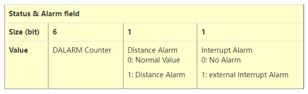
| Value | BAT | Object1 Distance | Object2 Distance | Status & Alarm |
Object1 Distance:
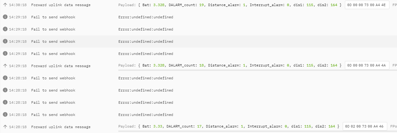
Distance between sensor probe to the first object. (unit: cm)
For example, if the data you get from the register is 0x00 0x73, the distance between the sensor and the measured object is 0073(H) = 115 (D) = 115 cm.
Notice: There are two special values for object 1 distance:
0x0001: Probe not detected
0x0002: Reading Invalid (exceed the valid range of the probe)
Object2 Distance:
Distance between sensor probe to the second object. (unit: cm)
DALARM Counter : Alarm Counter.
2.3.6 Decoder in TTN V3
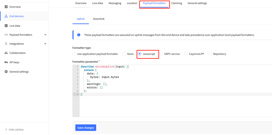
Please check the decoder from this link:
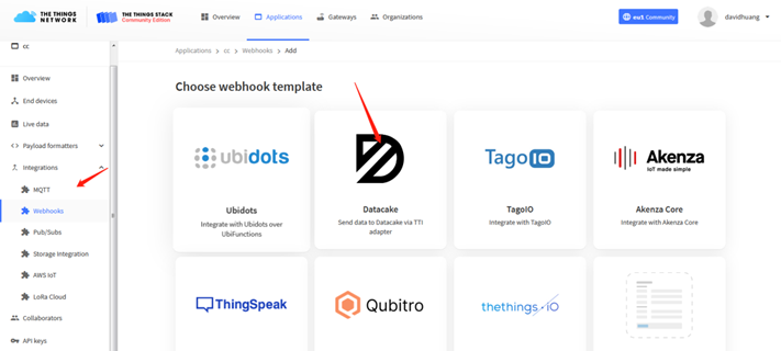
2.4 Show data on Datacake
DATACAKE provides a human friendly interface to show the sensor data, once we have data in TTN, we can use DATACAKE to connect to TTN and see the data in DATACAKE. Below are the steps:
Step 1: Be sure that your device is programmed and properly connected to the network at this time.
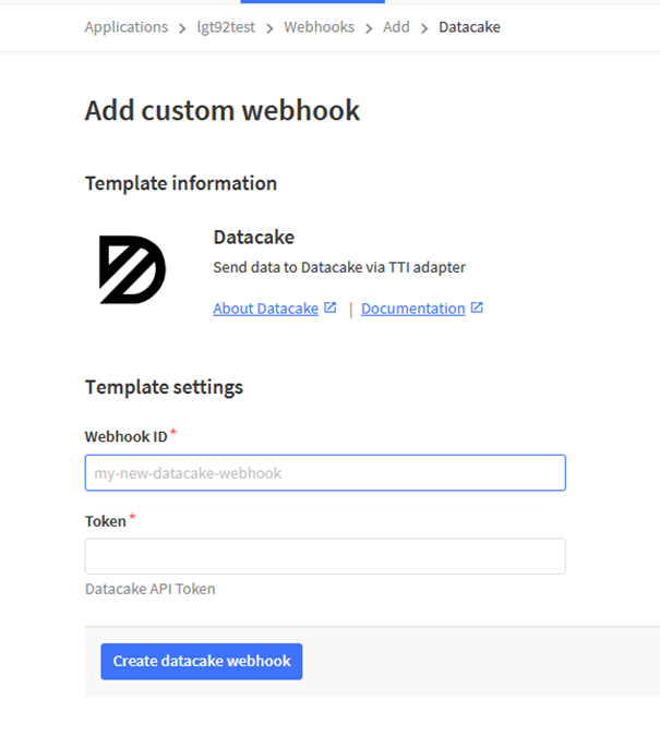
Step 2: To configure the Application to forward data to DATACAKE you will need to add integration. To add the DATACAKE integration, perform the following steps:
Step 3: Create an account or log in Datacake.
Step 4: Search the LDDS75 and add DevEUI.(Note: LDDS20 use same payload as LDDS75)
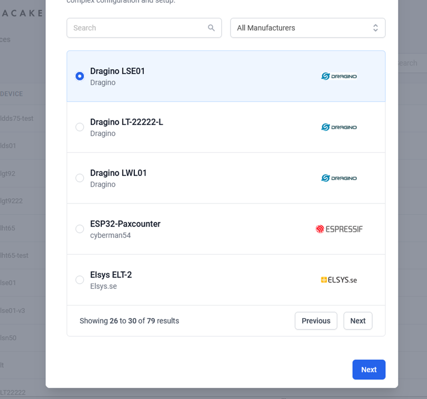
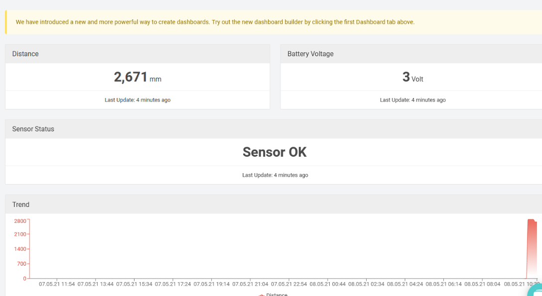
After added, the sensor data arrive TTN V3, it will also arrive and show in Datacake.
2.6 LED Indicator
The LDDS20 has an internal LED which is to show the status of different state.
- Blink once when device power on.
- The device detects the sensor and flashes 5 times.
- Solid ON for 5 seconds once device successful Join the network.
- Blink once when device transmit a packet.
2.7 Firmware Change Log
Firmware download link: http://www.dragino.com/downloads/index.php?dir=LoRa_End_Node/LSE01/Firmware/
Firmware Upgrade Method: Firmware Upgrade Instruction
2.8 Battery Analysis
2.8.1 Battery Type
The LDDS20 battery is a combination of a 8500mAh Li/SOCI2 Battery and a Super Capacitor. The battery is non-rechargeable battery type with a low discharge rate (<2% per year). This type of battery is commonly used in IoT devices such as water meter.
The battery related documents as below:
2.8.2 Battery Note
The Li-SICO battery is designed for small current / long period application. It is not good to use a high current, short period transmit method. The recommended minimum period for use of this battery is 5 minutes. If you use a shorter period time to uplink data, then the battery life may be decreased.
2.8.3 Replace the battery
You can change the battery in the NBSN95.The type of battery is not limited as long as the output is between 3v to 3.6v. On the main board, there is a diode (D1) between the battery and the main circuit. If you need to use a battery with less than 3.3v, please remove the D1 and shortcut the two pads of it so there won’t be voltage drop between battery and main board.
The default battery pack of NBSN95 includes a ER26500 plus super capacitor. If user can't find this pack locally, they can find ER26500 or equivalence without the SPC1520 capacitor, which will also work in most case. The SPC can enlarge the battery life for high frequency use (update period below 5 minutes)
2.8.4 Battery Life Analyze
Dragino battery powered products are all run in Low Power mode. User can check the guideline from this link to calculate the estimate battery life:
3. Using the AT Commands
3.1 Access AT Commands
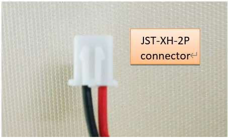
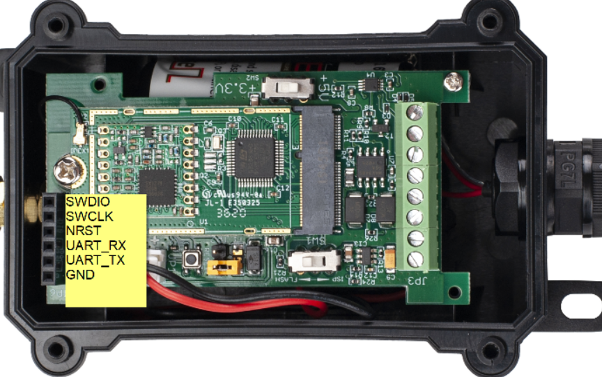
LDDS20 supports AT Command set in the stock firmware. You can use a USB to TTL adapter to connect to LDDS20 for using AT command, as below.
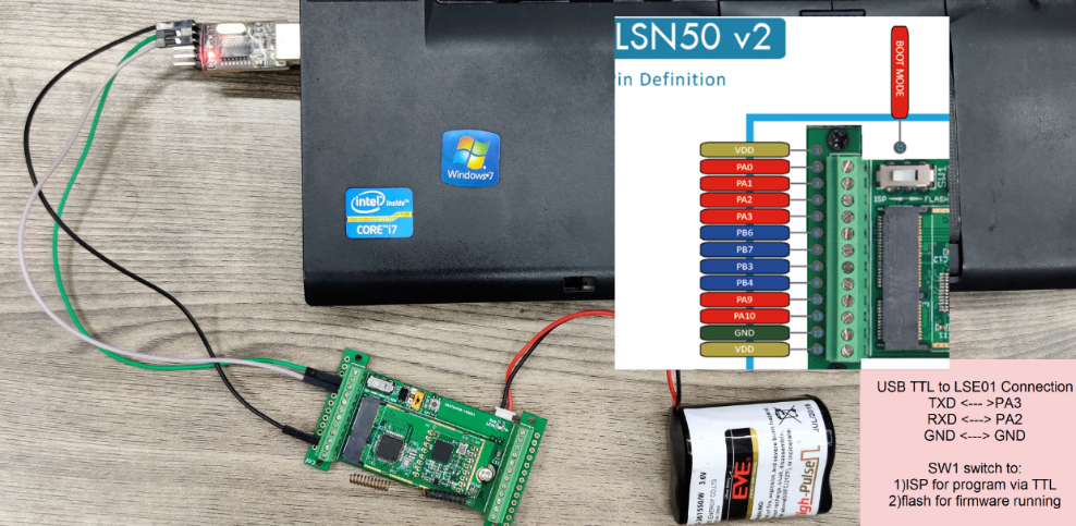
Or if you have below board, use below connection:
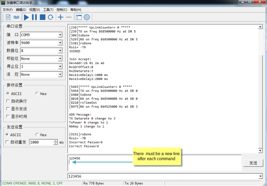
In the PC, you need to set the serial baud rate to 9600 to access the serial console for LDDS20. LDDS20 will output system info once power on as below:
Below are the available commands, a more detailed AT Command manual can be found at AT Command Manual.
AT+<CMD>? : Help on <CMD>
AT+<CMD> : Run <CMD>
AT+<CMD>=<value> : Set the value
AT+<CMD>=? : Get the value
General Commands :
AT : Attention
AT? : Short Help
ATZ : MCU Reset
AT+TDC : Application Data Transmission Interval
Keys, IDs and EUIs management :
AT+APPEUI : Application EUI
AT+APPKEY : Application Key
AT+APPSKEY : Application Session Key
AT+DADDR : Device Address
AT+DEUI : Device EUI
AT+NWKID : Network ID (You can enter this command change only after successful network connection)
AT+NWKSKEY : Network Session Key Joining and sending date on LoRa network
AT+CFM : Confirm Mode
AT+CFS : Confirm Status
AT+JOIN : Join LoRa? Network
AT+NJM : LoRa? Network Join Mode
AT+NJS : LoRa? Network Join Status
AT+RECV : Print Last Received Data in Raw Format
AT+RECVB : Print Last Received Data in Binary Format
AT+SEND : Send Text Data
AT+SENB : Send Hexadecimal Data
LoRa Network Management :
AT+ADR : Adaptive Rate
AT+CLASS : LoRa Class(Currently only support class A
AT+DCS : Duty Cycle Setting
AT+DR : Data Rate (Can Only be Modified after ADR=0)
AT+FCD : Frame Counter Downlink
AT+FCU : Frame Counter Uplink
AT+JN1DL : Join Accept Delay1
AT+JN2DL : Join Accept Delay2
AT+PNM : Public Network Mode
AT+RX1DL : Receive Delay1
AT+RX2DL : Receive Delay2
AT+RX2DR : Rx2 Window Data Rate
AT+RX2FQ : Rx2 Window Frequency
AT+TXP : Transmit Power
Information :
AT+RSSI : RSSI of the Last Received Packet
AT+SNR : SNR of the Last Received Packet
AT+VER : Image Version and Frequency Band
AT+FDR : Factory Data Reset
AT+PORT : Application Port
AT+CHS : Get or Set Frequency (Unit: Hz) for Single Channel Mode
AT+CHE : Get or Set eight channels mode, Only for US915, AU915, CN470
3.2 Set Interrupt Mode
Feature, Set Interrupt mode for GPIO_EXIT.
Downlink Command: AT+INTMOD
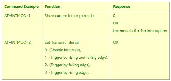
Downlink Command: 0x06
Format: Command Code (0x06) followed by 3 bytes.
This means that the interrupt mode of the end node is set to 0x000003=3 (rising edge trigger), and the type code is 06.
Example 1: Downlink Payload: 06000000 // Turn off interrupt mode
Example 2: Downlink Payload: 06000003 // Set the interrupt mode to rising edge trigger
4. FAQ
4.1 What is the frequency plan for LDDS20?
LDDS20 use the same frequency as other Dragino products. User can see the detail from this link: Introduction
4.2 How to change the LoRa Frequency Bands/Region
You can follow the instructions for how to upgrade image.
When downloading the images, choose the required image file for download.
5. Trouble Shooting
5.1 Why I can't join TTN V3 in US915 / AU915 bands?
It is due to channel mapping. Please see below link: Frequency band
5.2 AT Command input doesn't work
In the case if user can see the console output but can't type input to the device. Please check if you already include the ENTER while sending out the command. Some serial tool doesn't send ENTER while press the send key, user need to add ENTER in their string.
6. Order Info
Part Number : LDDS20-XX
XX: The default frequency band
- AS923 : LoRaWAN AS923 band
- AU915 : LoRaWAN AU915 band
- EU433 : LoRaWAN EU433 band
- EU868 : LoRaWAN EU868 band
- KR920 : LoRaWAN KR920 band
- US915 : LoRaWAN US915 band
- IN865 : LoRaWAN IN865 band
- CN470 : LoRaWAN CN470 band
7. Packing Info
Package Includes:
LDDS20 LoRaWAN Liquid Level Sensor x 1
Note:
Ultrasonic coupling paste and Eproxy AB glue are subjected in most shipping way. So the default package doesn't include it and user needs to purchase locally.
Dimension and weight:
Device Size: cm
Device Weight: g
Package Size / pcs : cm
Weight / pcs : g
8. Support
- Support is provided Monday to Friday, from 09:00 to 18:00 GMT+8. Due to different timezones we cannot offer live support. However, your questions will be answered as soon as possible in the before-mentioned schedule.
- Provide as much information as possible regarding your enquiry (product models, accurately describe your problem and steps to replicate it etc) and send a mail to support@dragino.com.