Contents:
1. Introduction
1.1 What is LoRaWAN Distance Detection Sensor
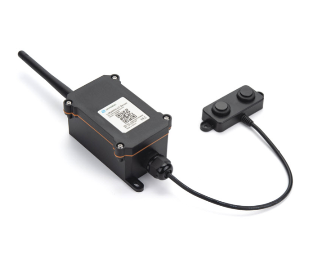
The Dragino LDDS45 is a LoRaWAN Distance Detection Sensor for Internet of Things solution. It is used to measure the distance between the sensor and a flat object. The distance detection sensor is a module that uses ultrasonic sensing technology for distance measurement, and temperature compensation is performed internally to improve the reliability of data. The LDDS45 can be applied to scenarios such as horizontal distance measurement, liquid level measurement, parking management system, object proximity and presence detection, intelligent trash can management system, robot obstacle avoidance, automatic control, sewer, bottom water level monitoring, etc.
It detects the distance between the measured object and the sensor, and uploads the value via wireless to LoRaWAN IoT Server.
The LoRa wireless technology used in LDDS45 allows device to send data and reach extremely long ranges at low data-rates. It provides ultra-long range spread spectrum communication and high interference immunity whilst minimizing current consumption.
LDDS45 is powered by 8500mAh Li-SOCI2 battery; It is designed for long term use up to 10 years*.
Each LDDS45 pre-loads with a set of unique keys for LoRaWAN registrations, register these keys to local LoRaWAN server and it will auto connect if there is network coverage, after power on.
* Actually lifetime depends on network coverage and uplink interval and other factors.

1.2 Features
- LoRaWAN 1.0.3 Class A
- Ultra-low power consumption
- Distance Detection by Ultrasonic technology
- Flat object range 30mm - 4500mm
- Accuracy: ±(1cm+S*0.3%) (S: Distance)
- Measure Angle: 60°
- Cable Length : 25cm
- Bands: CN470/EU433/KR920/US915/EU868/AS923/AU915/IN865
- AT Commands to change parameters
- Uplink on periodically
- Downlink to change configure
- IP66 Waterproof Enclosure
- 8500mAh Battery for long term use
1.3 Specification
1.3.1 Rated environmental conditions
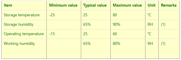
Remarks: (1) a. When the ambient temperature is 0-39 ℃, the maximum humidity is 90% (non-condensing);
b. When the ambient temperature is 40-50 ℃, the highest humidity is the highest humidity in the natural world at the current temperature (no condensation)
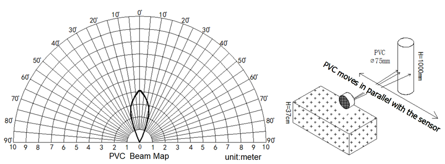
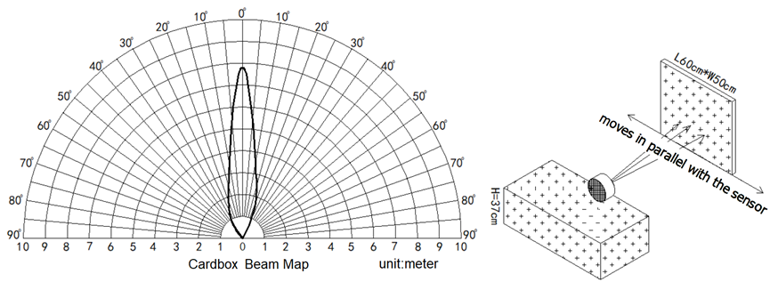
1.3.2 Effective measurement range Reference beam pattern
(1) The tested object is a white cylindrical tube made of PVC, with a height of 100cm and a diameter of 7.5cm.
(2) The object to be tested is a "corrugated cardboard box" perpendicular to the central axis of 0 °, and the length * width is 60cm * 50cm.
1.5 Applications
- Horizontal distance measurement
- Liquid level measurement
- Parking management system
- Object proximity and presence detection
- Intelligent trash can management system
- Robot obstacle avoidance
- Automatic control
- Sewer
- Bottom water level monitoring
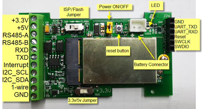
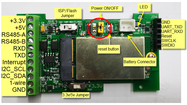
1.6 Pin mapping and power on
2. Configure LDDS45 to connect to LoRaWAN network
2.1 How it works
The LDDS45 is configured as LoRaWAN OTAA Class A mode by default. It has OTAA keys to join LoRaWAN network. To connect a LoRaWAN network, you need to input the OTAA keys in the LoRaWAN IoT server and power on the LDDS45. If there is coverage of the LoRaWAN network, it will automatically join the network via OTAA and start to send the sensor value
In case you can't set the OTAA keys in the LoRaWAN OTAA server, and you have to use the keys from the server, you can use AT Commands to set the keys in the LDDS45.
2.2 Quick guide to connect to LoRaWAN server (OTAA)
Following is an example for how to join the TTN v3 LoRaWAN Network. Below is the network structure; we use the LG308 as a LoRaWAN gateway in this example.
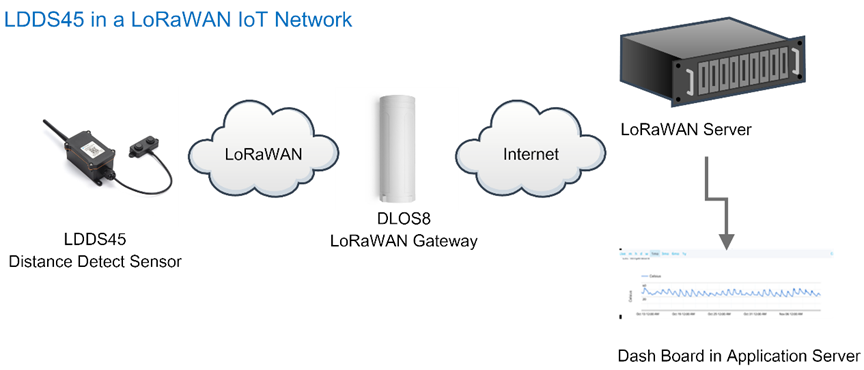
The LG308 is already set to connected to TTN network , so what we need to now is configure the TTN server.
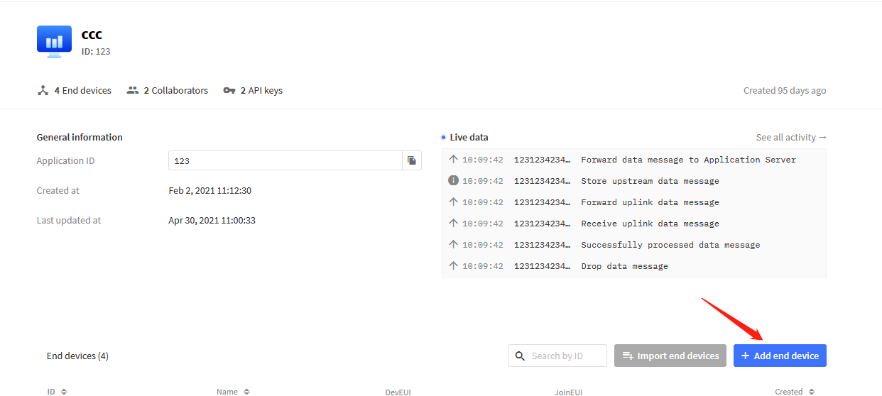
Step 1: Create a device in TTN with the OTAA keys from LDDS45.
Each LDDS45 is shipped with a sticker with the default device keys, user can find this sticker in the box. it looks like below.
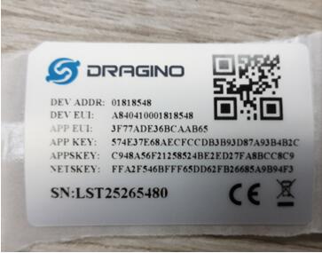
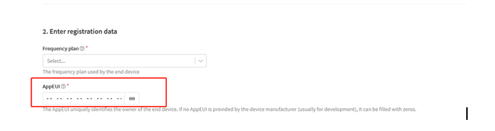
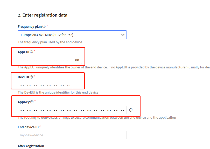
For OTAA registration, we need to set APP EUI/ APP KEY/ DEV EUI. Some server might no need to set APP EUI.
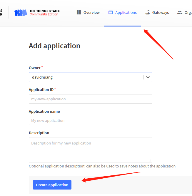
Enter these keys in the LoRaWAN Server portal. Below is TTN V3 screen shot:
Add APP EUI in the application
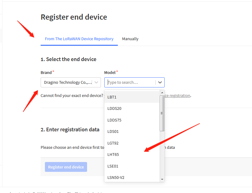
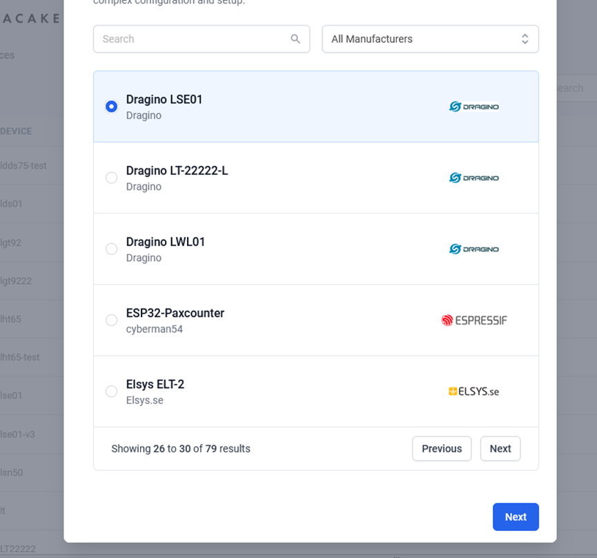
Choose LDDS75 instead of LDDS45 is ok. They are of the same payload
You can also choose to create the device manually.
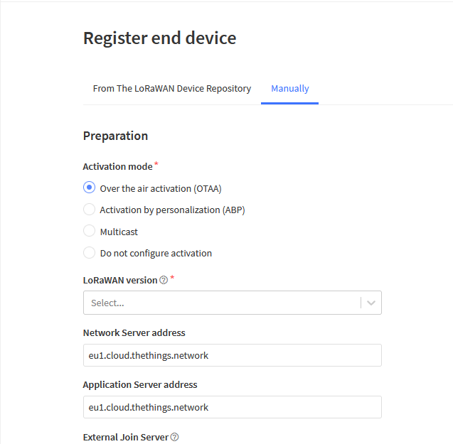
Add APP KEY and DEV EUI
Step 2: Power on LDDS45
Put a Jumper on JP2 to power on the device. ( The Switch must be in FLASH position).
Step 3: The LDDS45 will auto join to the TTN network. After join success, it will start to upload messages to TTN and you can see the messages in the panel.
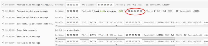
2.3 Uplink Payload
LDDS45 will uplink payload via LoRaWAN with below payload format:
Uplink payload includes in total 8 bytes.
Size (bytes) | 2 | 2 | 1 | 2 | 1 |
|---|---|---|---|---|---|
| Value | BAT | (unit: mm) | Digital Interrupt (Optional) | Sensor Flag |

2.3.1 Battery Info
Check the battery voltage for LDDS45.
Ex1: 0x0B45 = 2885mV
Ex2: 0x0B49 = 2889mV
2.3.2 Distance
Get the distance. Flat object range 30mm - 4500mm.
For example, if the data you get from the register is 0x0B 0x05, the distance between the sensor and the measured object is 0B05(H) = 2821 (D) = 2821 mm.
- If the sensor value is 0x0000, it means system doesn’t detect ultrasonic sensor.
- If the sensor value lower than 0x001E (30mm), the sensor value will be 0x00.
2.3.3 Interrupt Pin
This data field shows if this packet is generated by interrupt or not. Click here for the hardware and software set up.
Example:
0x00: Normal uplink packet.
0x01: Interrupt Uplink Packet.
2.3.4 DS18B20 Temperature sensor
This is optional, user can connect external DS18B20 sensor to the +3.3v, 1-wire and GND pin . and this field will report temperature.
Example:
If payload is: 0105H: (0105 & FC00 == 0), temp = 0105H /10 = 26.1 degree
If payload is: FF3FH : (FF3F & FC00 == 1) , temp = (FF3FH - 65536)/10 = -19.3 degrees.
2.3.5 Sensor Flag
0x01: Detect Ultrasonic Sensor
0x00: No Ultrasonic Sensor
2.3.6 Decode payload in The Things Network
While using TTN network, you can add the payload format to decode the payload.
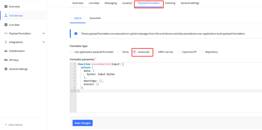
The payload decoder function for TTN V3 is here:
LDDS45 TTN V3 Payload Decoder: http://www.dragino.com/downloads/index.php?dir=LoRa_End_Node/LDDS75/Payload_Decoder/
2.4 Uplink Interval
The LDDS45 by default uplink the sensor data every 20 minutes. User can change this interval by AT Command or LoRaWAN Downlink Command. See this link: Change Uplink Interval
2.5 Show Data in DataCake IoT Server
DATACAKE provides a human friendly interface to show the sensor data, once we have data in TTN, we can use DATACAKE to connect to TTN and see the data in DATACAKE. Below are the steps:
Step 1: Be sure that your device is programmed and properly connected to the network at this time.
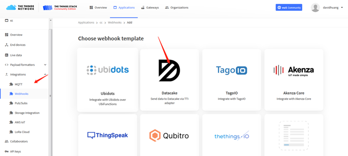
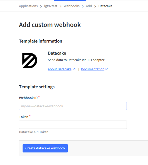
Step 2: To configure the Application to forward data to DATACAKE you will need to add integration. To add the DATACAKE integration, perform the following steps:
Step 3: Create an account or log in Datacake.
Step 4: Search the LDDS45 and add DevEUI.
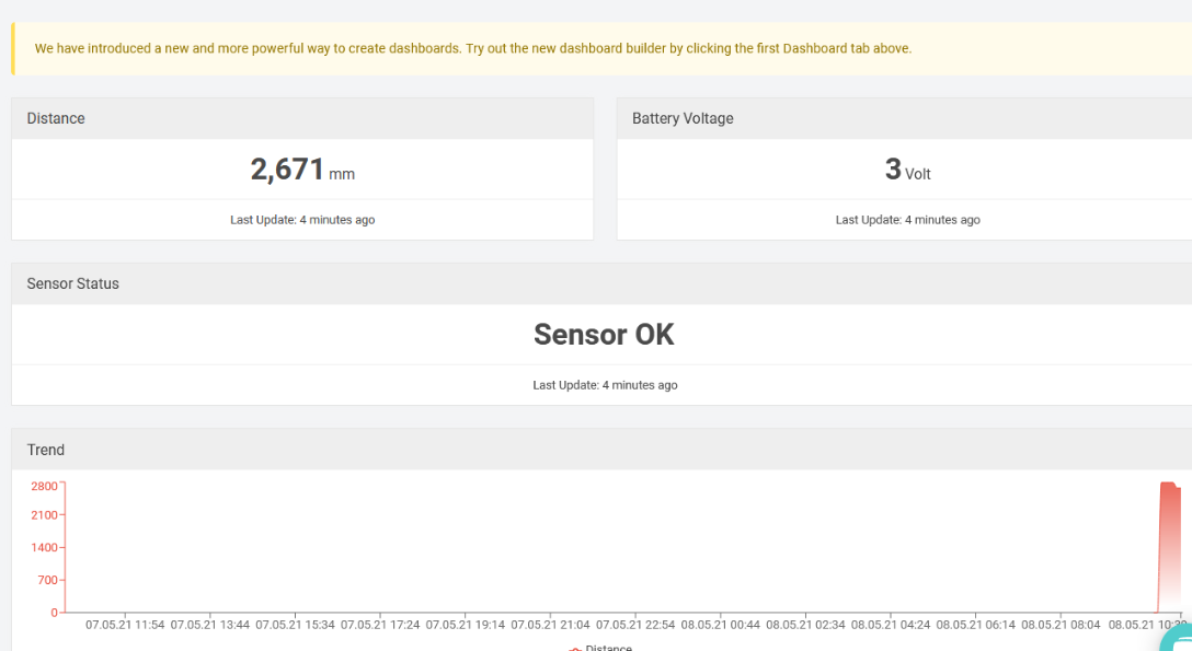
After added, the sensor data arrive TTN V3, it will also arrive and show in Datacake.
2.6 Frequency Plans
The LDDS45 uses OTAA mode and below frequency plans by default. If user want to use it with different frequency plan, please refer the AT command sets.
2.6.1 EU863-870 (EU868)
Uplink:
868.1 - SF7BW125 to SF12BW125
868.3 - SF7BW125 to SF12BW125 and SF7BW250
868.5 - SF7BW125 to SF12BW125
867.1 - SF7BW125 to SF12BW125
867.3 - SF7BW125 to SF12BW125
867.5 - SF7BW125 to SF12BW125
867.7 - SF7BW125 to SF12BW125
867.9 - SF7BW125 to SF12BW125
868.8 - FSK
Downlink:
Uplink channels 1-9 (RX1)
869.525 - SF9BW125 (RX2 downlink only)
2.6.2 US902-928(US915)
Used in USA, Canada and South America. Default use CHE=2
Uplink:
903.9 - SF7BW125 to SF10BW125
904.1 - SF7BW125 to SF10BW125
904.3 - SF7BW125 to SF10BW125
904.5 - SF7BW125 to SF10BW125
904.7 - SF7BW125 to SF10BW125
904.9 - SF7BW125 to SF10BW125
905.1 - SF7BW125 to SF10BW125
905.3 - SF7BW125 to SF10BW125
Downlink:
923.3 - SF7BW500 to SF12BW500
923.9 - SF7BW500 to SF12BW500
924.5 - SF7BW500 to SF12BW500
925.1 - SF7BW500 to SF12BW500
925.7 - SF7BW500 to SF12BW500
926.3 - SF7BW500 to SF12BW500
926.9 - SF7BW500 to SF12BW500
927.5 - SF7BW500 to SF12BW500
923.3 - SF12BW500(RX2 downlink only)
2.6.3 CN470-510 (CN470)
Used in China, Default use CHE=1
Uplink:
486.3 - SF7BW125 to SF12BW125
486.5 - SF7BW125 to SF12BW125
486.7 - SF7BW125 to SF12BW125
486.9 - SF7BW125 to SF12BW125
487.1 - SF7BW125 to SF12BW125
487.3 - SF7BW125 to SF12BW125
487.5 - SF7BW125 to SF12BW125
487.7 - SF7BW125 to SF12BW125
Downlink:
506.7 - SF7BW125 to SF12BW125
506.9 - SF7BW125 to SF12BW125
507.1 - SF7BW125 to SF12BW125
507.3 - SF7BW125 to SF12BW125
507.5 - SF7BW125 to SF12BW125
507.7 - SF7BW125 to SF12BW125
507.9 - SF7BW125 to SF12BW125
508.1 - SF7BW125 to SF12BW125
505.3 - SF12BW125 (RX2 downlink only)
2.6.4 AU915-928(AU915)
Default use CHE=2
Uplink:
916.8 - SF7BW125 to SF12BW125
917.0 - SF7BW125 to SF12BW125
917.2 - SF7BW125 to SF12BW125
917.4 - SF7BW125 to SF12BW125
917.6 - SF7BW125 to SF12BW125
917.8 - SF7BW125 to SF12BW125
918.0 - SF7BW125 to SF12BW125
918.2 - SF7BW125 to SF12BW125
Downlink:
923.3 - SF7BW500 to SF12BW500
923.9 - SF7BW500 to SF12BW500
924.5 - SF7BW500 to SF12BW500
925.1 - SF7BW500 to SF12BW500
925.7 - SF7BW500 to SF12BW500
926.3 - SF7BW500 to SF12BW500
926.9 - SF7BW500 to SF12BW500
927.5 - SF7BW500 to SF12BW500
923.3 - SF12BW500(RX2 downlink only)
2.6.5 AS920-923 & AS923-925 (AS923)
Default Uplink channel:
923.2 - SF7BW125 to SF10BW125
923.4 - SF7BW125 to SF10BW125
Additional Uplink Channel:
(OTAA mode, channel added by JoinAccept message)
AS920~AS923 for Japan, Malaysia, Singapore:
922.2 - SF7BW125 to SF10BW125
922.4 - SF7BW125 to SF10BW125
922.6 - SF7BW125 to SF10BW125
922.8 - SF7BW125 to SF10BW125
923.0 - SF7BW125 to SF10BW125
922.0 - SF7BW125 to SF10BW125
AS923 ~ AS925 for Brunei, Cambodia, Hong Kong, Indonesia, Laos, Taiwan, Thailand, Vietnam:
923.6 - SF7BW125 to SF10BW125
923.8 - SF7BW125 to SF10BW125
924.0 - SF7BW125 to SF10BW125
924.2 - SF7BW125 to SF10BW125
924.4 - SF7BW125 to SF10BW125
924.6 - SF7BW125 to SF10BW125
Downlink:
Uplink channels 1-8 (RX1)
923.2 - SF10BW125 (RX2)
2.6.6 KR920-923 (KR920)
Default channel:
922.1 - SF7BW125 to SF12BW125
922.3 - SF7BW125 to SF12BW125
922.5 - SF7BW125 to SF12BW125
Uplink: (OTAA mode, channel added by JoinAccept message)
922.1 - SF7BW125 to SF12BW125
922.3 - SF7BW125 to SF12BW125
922.5 - SF7BW125 to SF12BW125
922.7 - SF7BW125 to SF12BW125
922.9 - SF7BW125 to SF12BW125
923.1 - SF7BW125 to SF12BW125
923.3 - SF7BW125 to SF12BW125
Downlink:
Uplink channels 1-7(RX1)
921.9 - SF12BW125 (RX2 downlink only; SF12BW125 might be changed to SF9BW125)
2.6.7 IN865-867 (IN865)
Uplink:
865.0625 - SF7BW125 to SF12BW125
865.4025 - SF7BW125 to SF12BW125
865.9850 - SF7BW125 to SF12BW125
Downlink:
Uplink channels 1-3 (RX1)
866.550 - SF10BW125 (RX2)
2.7 LED Indicator
The LDDS45 has an internal LED which is to show the status of different state.
- Blink once when device power on.
- The device detects the sensor and flashes 5 times.
- Solid ON for 5 seconds once device successful Join the network.
- Blink once when device transmit a packet.
2.8 Firmware Change Log
Firmware download link: http://www.dragino.com/downloads/index.php?dir=LoRa_End_Node/LDDS75/Firmware/
Firmware Upgrade Method: Firmware Upgrade Instruction
2.9 Mechanical
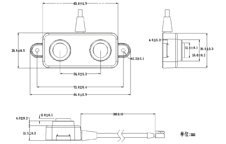
![]()
3. Battery & How to replace
3.1 Battery Type
LDDS45 is equipped with a 8500mAH ER26500 Li-SOCI2 battery. The battery is un-rechargeable battery with low discharge rate targeting for 8~10 years use. This type of battery is commonly used in IoT target for long-term running, such as water meter.
The discharge curve is not linear so can’t simply use percentage to show the battery level. Below is the battery performance.
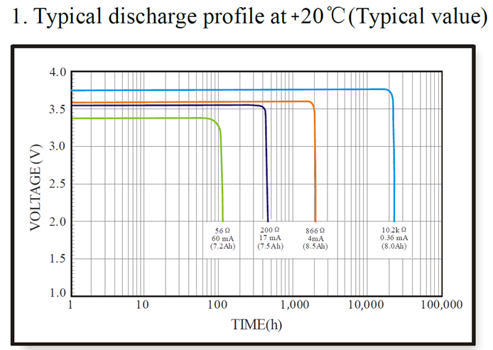
![]()
Minimum Working Voltage for the LDDS45:
LDDS45: 2.45v ~ 3.6v
3.2 Replace Battery
Any battery with range 2.45 ~ 3.6v can be a replacement. We recommend to use Li-SOCl2 Battery.
And make sure the positive and negative pins match.
3.3 Power Consumption Analyze
Dragino Battery powered product are all runs in Low Power mode. We have an update battery calculator which base on the measurement of the real device. User can use this calculator to check the battery life and calculate the battery life if want to use different transmit interval.
Instruction to use as below:
Step 1 : Downlink the up-to-date DRAGINO_Battery_Life_Prediction_Table.xlsx from:
https://www.dragino.com/downloads/index.pHp?dir=LoRa_End_Node/Battery_Analyze/
Step 2 : Open it and choose
- Product Model
- Uplink Interval
- Working Mode
And the Life expectation in difference case will be shown on the right.
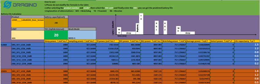
![]()
The battery related documents as below:

![]()
3.3.1 Battery Note
The Li-SICO battery is designed for small current / long period application. It is not good to use a high current, short period transmit method. The recommended minimum period for use of this battery is 5 minutes. If you use a shorter period time to transmit LoRa, then the battery life may be decreased.
3.3.2 Replace the battery
You can change the battery in the LSPH01.The type of battery is not limited as long as the output is between 3v to 3.6v. On the main board, there is a diode (D1) between the battery and the main circuit. If you need to use a battery with less than 3.3v, please remove the D1 and shortcut the two pads of it so there won’t be voltage drop between battery and main board.
The default battery pack of LSPH01 includes a ER26500 plus super capacitor. If user can’t find this pack locally, they can find ER26500 or equivalence, which will also work in most case. The SPC can enlarge the battery life for high frequency use (update period below 5 minutes).
4. Configure LDDS45 via AT Command or LoRaWAN Downlink
Use can configure LDDS45 via AT Command or LoRaWAN Downlink.
AT Command Connection: See FAQ.
LoRaWAN Downlink instruction for different platforms: IoT LoRaWAN Server
There are two kinds of commands to configure LDDS45, they are:
General Commands.
These commands are to configure:
General system settings like: uplink interval.
LoRaWAN protocol & radio related command.
They are same for all Dragino Device which support DLWS-005 LoRaWAN Stack. These commands can be found on the wiki: End Device AT Commands and Downlink Command
Commands special design for LDDS45
These commands only valid for LDDS45, as below:
4.1 Access AT Commands
User can use a USB to TTL adapter to connect to LDDS45 and access the console to enter AT Commands. Note the TXD/RXD can use 3.3v or 5v.
Pins for console is:
- UART_TXD to USB TTL Adapter's RXD
- UART_RXD to USB TTL Adapter's TXD
- GND to USB TTL Adapter's GND
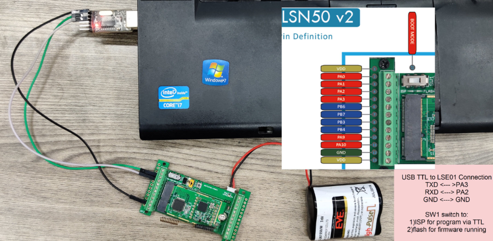
Or if you have below board, use below connection:
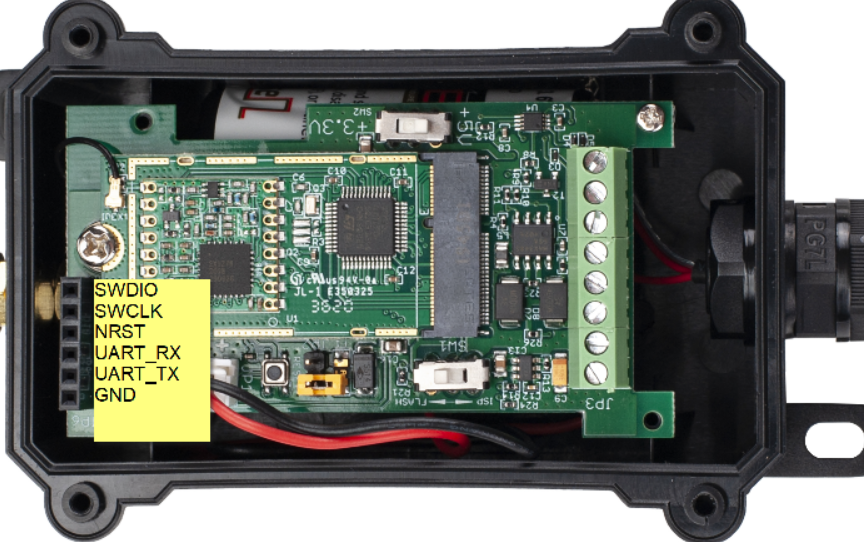
In the PC, you need to set the serial baud rate to 9600 to access the serial console for LDDS75. LDDS75 will output system info once power on as below:
4.2 Set Transmit Interval Time
Feature: Change LoRaWAN End Node Transmit Interval.
AT Command: AT+TDC
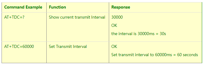
Downlink Command: 0x01
Format: Command Code (0x01) followed by 3 bytes time value.
If the downlink payload=0100003C, it means set the END Node’s Transmit Interval to 0x00003C=60(S), while type code is 01.
- Example 1: Downlink Payload: 0100001E // Set Transmit Interval (TDC) = 30 seconds
- Example 2: Downlink Payload: 0100003C // Set Transmit Interval (TDC) = 60 seconds
4.3 Set Interrupt Mode
Feature, Set Interrupt mode for GPIO_EXIT.
Downlink Command: AT+INTMOD
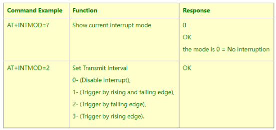
Downlink Command: 0x06
Format: Command Code (0x06) followed by 3 bytes.
This means that the interrupt mode of the end node is set to 0x000003=3 (rising edge trigger), and the type code is 06.
- Example 1: Downlink Payload: 06000000 // Turn off interrupt mode
- Example 2: Downlink Payload: 06000003 // Set the interrupt mode to rising edge trigger
5. FAQ
5.1 What is the frequency plan for LDDS75?
LDDS75 use the same frequency as other Dragino products. User can see the detail from this link: Introduction
5.2 How to change the LoRa Frequency Bands/Region
You can follow the instructions for how to upgrade image.
When downloading the images, choose the required image file for download.
5.3 Can I use LDDS75 in condensation environment?
LDDS75 is not suitable to be used in condensation environment. Condensation on the LDDS75 probe will affect the reading and always got 0.
6. Trouble Shooting
6.1 Why I can’t join TTN V3 in US915 / AU915 bands?
It is due to channel mapping. Please see below link: Frequency band
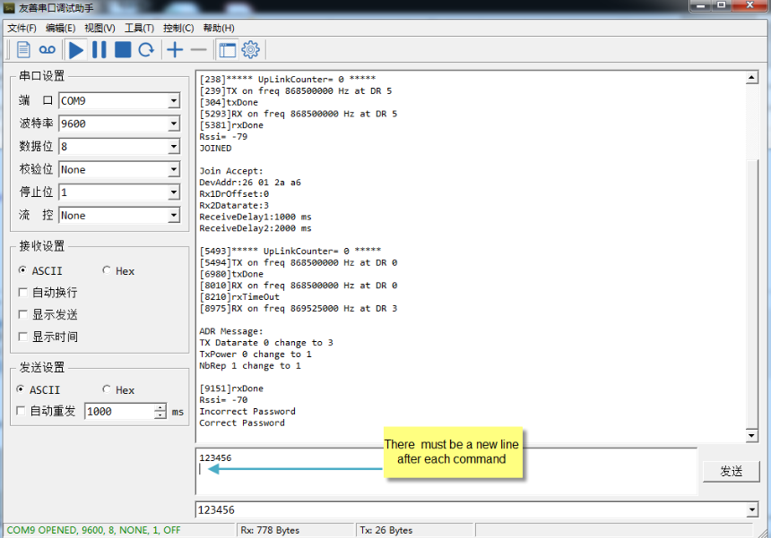
6.2 AT Command input doesn't work
In the case if user can see the console output but can’t type input to the device. Please check if you already include the ENTER while sending out the command. Some serial tool doesn’t send ENTER while press the send key, user need to add ENTER in their string.
7. Order Info
Part Number : LDDS75-XX-YY
XX: The default frequency band
- AS923 : LoRaWAN AS923 band
- AU915 : LoRaWAN AU915 band
- EU433 : LoRaWAN EU433 band
- EU868 : LoRaWAN EU868 band
- KR920 : LoRaWAN KR920 band
- US915 : LoRaWAN US915 band
- IN865 : LoRaWAN IN865 band
- CN470 : LoRaWAN CN470 band
YY: Battery Option
- 4 : 4000mAh battery
- 8 : 8500mAh battery
8. Packing Info
Package Includes:
- LDDS75 LoRaWAN Distance Detection Sensor x 1
Dimension and weight:
- Device Size: cm
- Device Weight: g
- Package Size / pcs : cm
- Weight / pcs : g
9. Support
- Support is provided Monday to Friday, from 09:00 to 18:00 GMT+8. Due to different timezones we cannot offer live support. However, your questions will be answered as soon as possible in the before-mentioned schedule.
- Provide as much information as possible regarding your enquiry (product models, accurately describe your problem and steps to replicate it etc) and send a mail to support@dragino.com.