Table of Contents:
1. Introduction
1.1 What is LoRaWAN Ultrasonic liquid level Sensor
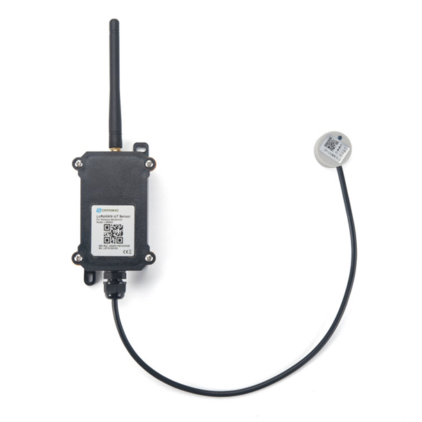
The Dragino LDDS20 is a LoRaWAN Ultrasonic liquid level sensor for Internet of Things solution. It uses none-contact method to measure the height of liquid in a container without opening the container, and send the value via LoRaWAN network to IoT Server
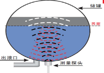
The LDDS20 sensor is installed directly below the container to detect the height of the liquid level. User doesn’t need to open a hole on the container to be tested. The none-contact measurement makes the measurement safety, easier and possible for some strict situation.
LDDS20 uses ultrasonic sensing technology for distance measurement. LDDS20 is of high accuracy to measure various liquid such as: toxic substances, strong acids, strong alkalis and various pure liquids in high-temperature and high-pressure airtight containers.
The LoRa wireless technology used in LDDS20 allows device to send data and reach extremely long ranges at low data-rates. It provides ultra-long range spread spectrum communication and high interference immunity whilst minimizing current consumption.
LDDS20 is powered by 8500mA Li-SOCI2 battery; It is designed for long term use up to 10 years*.
Each LDDS20 pre-loads with a set of unique keys for LoRaWAN registrations, register these keys to local LoRaWAN server and it will auto connect if there is network coverage, after power on.
* Actually lifetime depends on network coverage and uplink interval and other factors.

1.2 Features
- LoRaWAN 1.0.3 Class A
- Ultra low power consumption
- Liquid Level Measurement by Ultrasonic technology
- Measure through container, No need to contact Liquid.
- Valid level range 20mm - 2000mm
- Accuracy: ±(5mm+S*0.5%) (S: Measure Value)
- Cable Length : 25cm
- Bands: CN470/EU433/KR920/US915/EU868/AS923/AU915/IN865
- AT Commands to change parameters
- Uplink on periodically
- Downlink to change configure
- IP66 Waterproof Enclosure
- 8500mAh Battery for long term use
1.3 Suitable Container & Liquid
- Solid Wall container such as: steel, iron, glass, ceramics, non-foaming plastics etc.
- Container shape is regular, and surface is smooth.
- Container Thickness:
- Pure metal material. 2~8mm, best is 3~5mm
- Pure non metal material: <10 mm
- Pure liquid without irregular deposition.
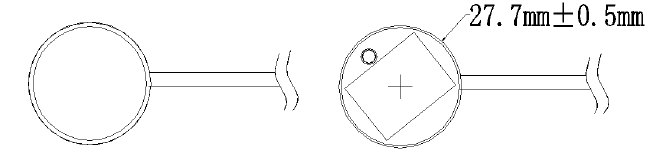
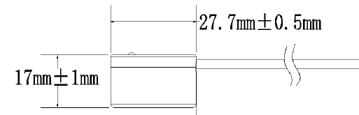
1.4 Mechanical
1.5 Install LDDS20
Step 1: Choose the installation point.
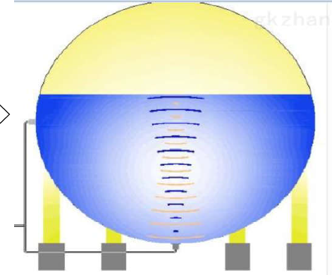
LDDS20 MUST be installed on the container bottom middle position.
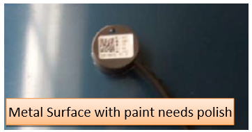
Step 2: Polish the installation point.
For Metal Surface with paint, it is important to polish the surface, first use crude sand paper to polish the paint level , then use exquisite sand paper to polish the metal level to make it shine & smooth.
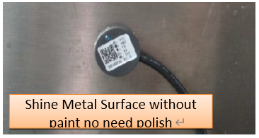
No polish needed if the container is shine metal surface without paint or non-metal container.
Step3: Test the installation point.
Power on LDDS75, check if the blue LED is on, If the blue LED is on, means the sensor works. Then put ultrasonic coupling paste on the sensor and put it tightly on the installation point.
It is necessary to put the coupling paste between the sensor and the container, otherwise LDDS20 won’t detect the liquid level.
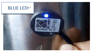
After paste the LDDS20 well, power on LDDS20. In the first 30 seconds of booting, device will check the sensors status and BLUE LED will show the status as below. After 30 seconds, BLUE LED will be off to save battery life.
LED Status:
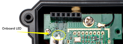
- Onboard LED: When power on device, the onboard LED will fast blink 4 times which means detect the sensor well.
- BLUE LED always ON: Sensor is power on but doesn’t detect liquid. There is problem in installation point.
- BLUE LED slowly blinking: Sensor detects Liquid Level, The installation point is good.
LDDS20 will enter into low power mode at 30 seconds after system reset or power on, Blue LED will be off after that.
Note 2:
Ultrasonic coupling paste is subjected in most shipping way. So the default package doesn’t include it and user needs to purchase locally.
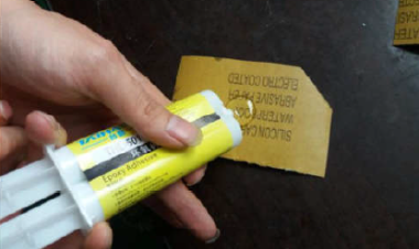
Step4: Install use Epoxy ab glue.
Prepare Eproxy AB glue.
Put Eproxy AB glue in the sensor and press it hard on the container installation point.
Reset LDDS20 and see if the BLUE LED is slowly blinking.
Note 1:
Eproxy AB glue needs 3~ 5 minutes to stable attached. we can use other glue material to keep it in the position.
Note 2:
Eproxy AB glue is subjected in most shipping way. So the default package doesn’t include it and user needs to purchase locally.
1.6 Applications
- Smart liquid control solution.
- Smart liquefied gas solution.
1.7 Precautions
- At room temperature, containers of different materials, such as steel, glass, iron, ceramics, non-foamed plastics and other dense materials, have different detection blind areas and detection limit heights.
- For containers of the same material at room temperature, the detection blind zone and detection limit height are also different for the thickness of the container.
- When the detected liquid level exceeds the effective detection value of the sensor, and the liquid level of the liquid to be measured shakes or tilts, the detected liquid height is unstable.
1.8 Pin mapping and power on
2. Configure LDDS20 to connect to LoRaWAN network
2.1 How it works
The LDDS20 is configured as LoRaWAN OTAA Class A mode by default. It has OTAA keys to join LoRaWAN network. To connect a LoRaWAN network, you need to input the OTAA keys in the LoRaWAN IoT server and power on the LDDS20. If there is coverage of the LoRaWAN network, it will automatically join the network via OTAA and start to send the sensor value.
In case you can't set the OTAA keys in the LoRaWAN OTAA server, and you have to use the keys from the server, you can use AT Commands to set the keys in the LDDS20.
2.2 Quick guide to connect to LoRaWAN server (OTAA)
Following is an example for how to join the TTN v3 LoRaWAN Network. Below is the network structure; we use the LG308 as a LoRaWAN gateway in this example.
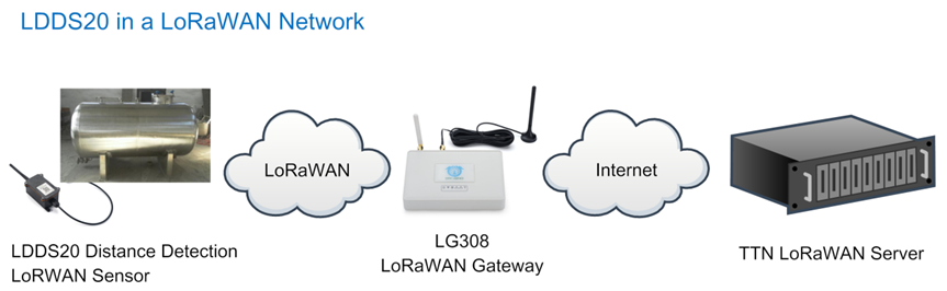
The LG308 is already set to connected to TTN network , so what we need to now is configure the TTN server.
Step 1: Create a device in TTN with the OTAA keys from LDDS20.
Each LDDS20 is shipped with a sticker with the default device keys, user can find this sticker in the box. it looks like below.
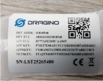
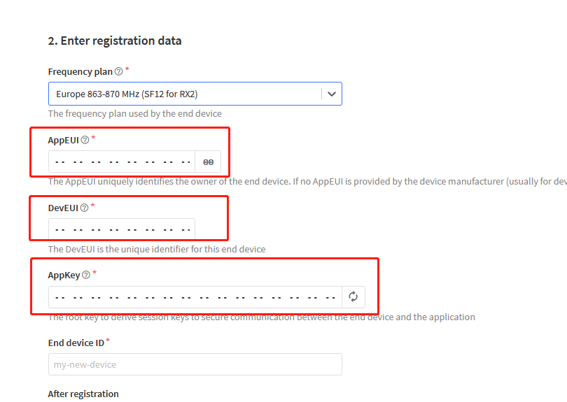
For OTAA registration, we need to set APP EUI/ APP KEY/ DEV EUI. Some server might no need to set APP EUI.
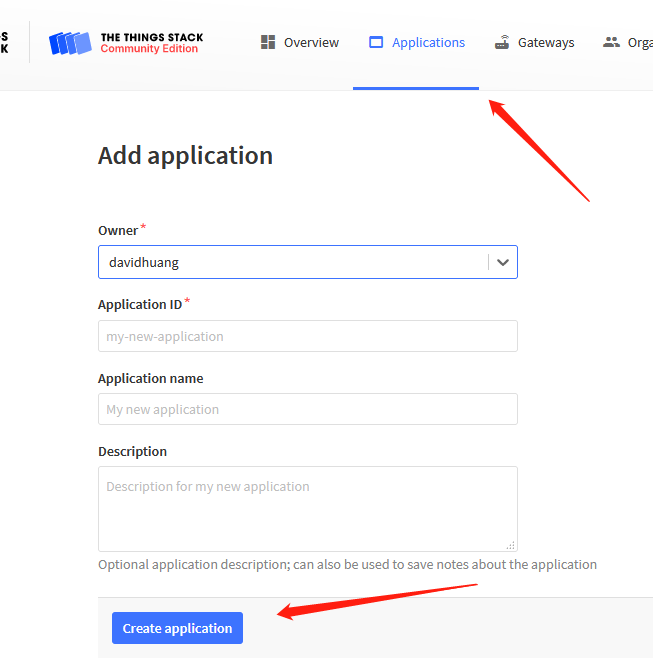
Enter these keys in the LoRaWAN Server portal. Below is TTN V3 screen shot:
Add APP EUI in the application
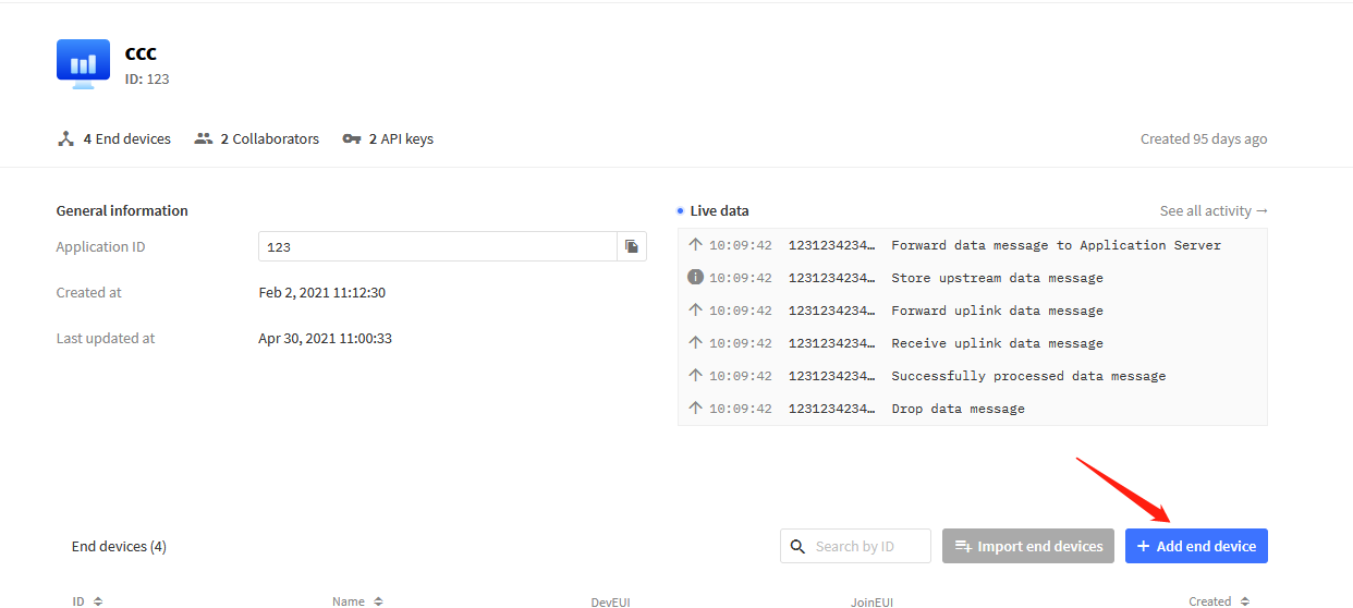
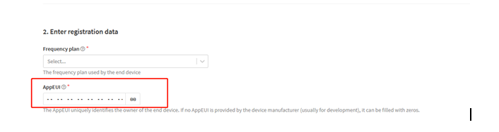
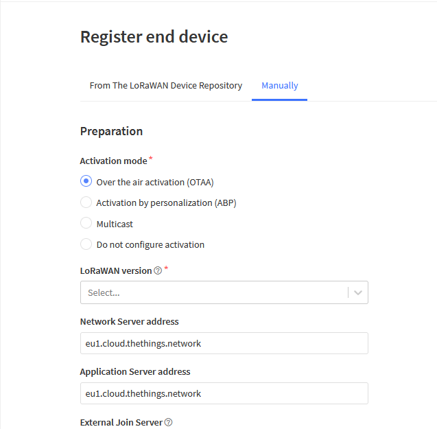
You can also choose to create the device manually.
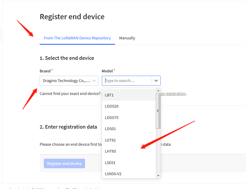
Add APP KEY and DEV EUI
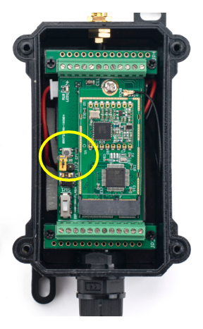
Step 2: Power on LDDS20
Put a Jumper on JP2 to power on the device. ( The Switch must be in FLASH position).
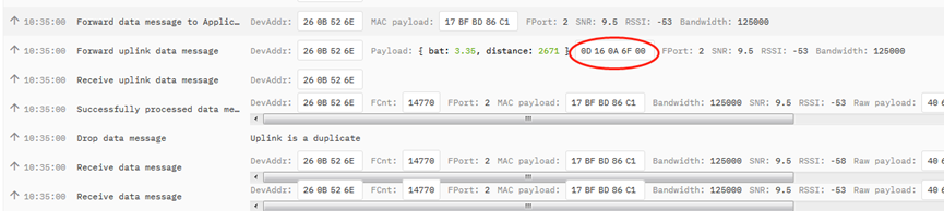
Step 3: The LDDS20 will auto join to the TTN network. After join success, it will start to upload messages to TTN and you can see the messages in the panel.

2.3 Uplink Payload
LDDS20 will uplink payload via LoRaWAN with below payload format:
Uplink payload includes in total 8 bytes.
Payload for firmware version v1.1.4. . Before v1.1.3, there is only 5 bytes: BAT and Distance(Please check manual v1.2.0 if you have 5 bytes payload).
Size (bytes) | 2 | 2 | 1 | 2 | 1 |
|---|---|---|---|---|---|
| Value | BAT | (unit: mm) | Digital Interrupt (Optional) | Sensor Flag |
2.3.1 Battery Info
Check the battery voltage for LDDS20.
Ex1: 0x0B45 = 2885mV
Ex2: 0x0B49 = 2889mV
2.3.2 Distance
Get the distance. Flat object range 20mm - 2000mm.
For example, if the data you get from the register is 0x06 0x05, the distance between the sensor and the measured object is 0605(H) = 1541 (D) = 1541 mm.
- If the sensor value is 0x0000, it means system doesn't detect ultrasonic sensor.
- If the sensor value lower than 0x0014 (20mm), the sensor value will be invalid.
2.3.3 Interrupt Pin
This data field shows if this packet is generated by interrupt or not. Click here for the hardware and software set up.
Example:
0x00: Normal uplink packet.
0x01: Interrupt Uplink Packet.
2.3.4 DS18B20 Temperature sensor
This is optional, user can connect external DS18B20 sensor to the +3.3v, 1-wire and GND pin . and this field will report temperature.
Example:
If payload is: 0105H: (0105 & FC00 == 0), temp = 0105H /10 = 26.1 degree
If payload is: FF3FH : (FF3F & FC00 == 1) , temp = (FF3FH - 65536)/10 = -19.3 degrees.
Note: DS18B20 feature is supported in the hardware version > v1.3 which made since early of 2021.
2.3.5 Sensor Flag
0x01: Detect Ultrasonic Sensor
0x00: No Ultrasonic Sensor
2.3.6 Decode payload in The Things Network
While using TTN network, you can add the payload format to decode the payload.
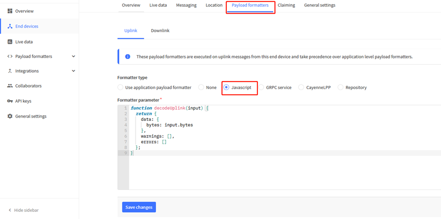
The payload decoder function for TTN V3 is here:
LDDS20 TTN V3 Payload Decoder: http://www.dragino.com/downloads/index.php?dir=LoRa_End_Node/LDDS20/Payload_Decoder/
2.4 Downlink Payload
By default, LDDS20 prints the downlink payload to console port.
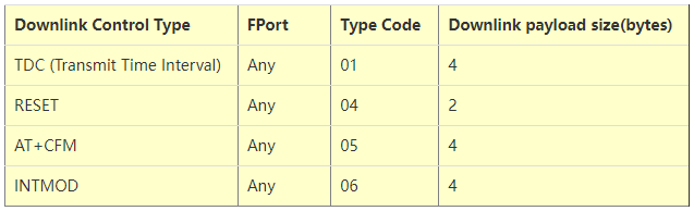
Examples:
- Set TDC
If the payload=0100003C, it means set the END Node's TDC to 0x00003C=60(S), while type code is 01.
Payload: 01 00 00 1E TDC=30S
Payload: 01 00 00 3C TDC=60S
- Reset
If payload = 0x04FF, it will reset the LDDS20
- CFM
Downlink Payload: 05000001, Set AT+CFM=1 or 05000000 , set AT+CFM=0
2.5 Show Data in DataCake IoT Server
DATACAKE provides a human friendly interface to show the sensor data, once we have data in TTN, we can use DATACAKE to connect to TTN and see the data in DATACAKE. Below are the steps:
Step 1: Be sure that your device is programmed and properly connected to the network at this time.
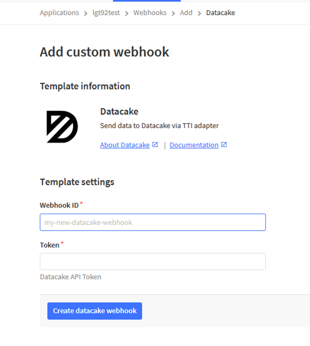
Step 2: To configure the Application to forward data to DATACAKE you will need to add integration. To add the DATACAKE integration, perform the following steps:
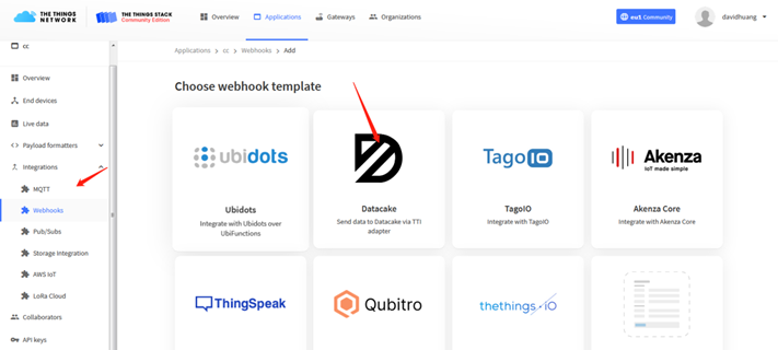
Step 3: Create an account or log in Datacake.
Step 4: Search the LDDS75 and add DevEUI.(Note: LDDS20 use same payload as LDDS75)
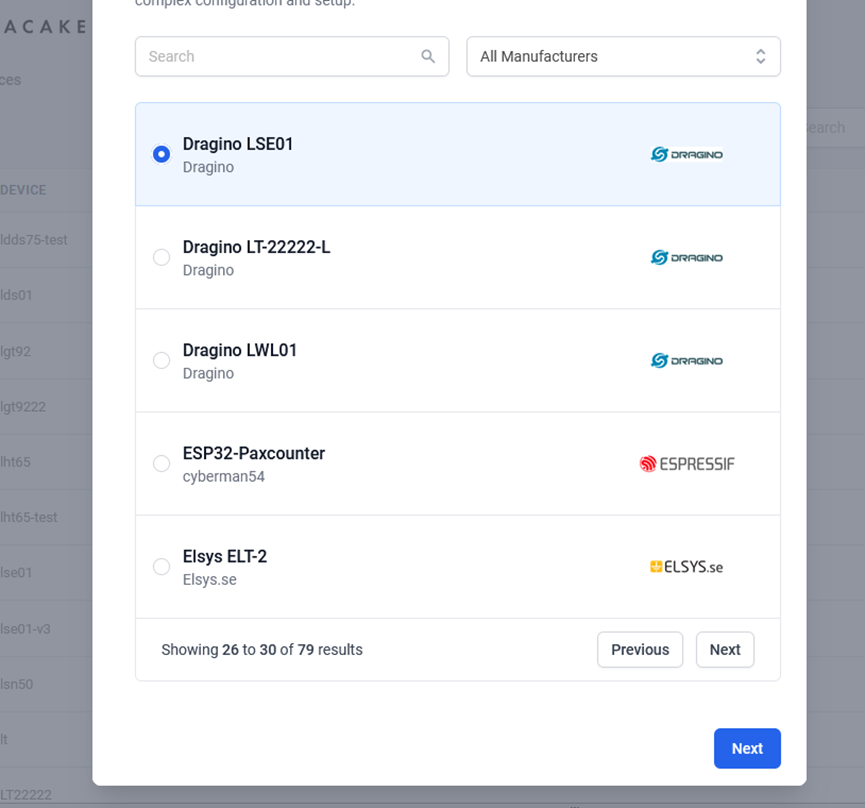
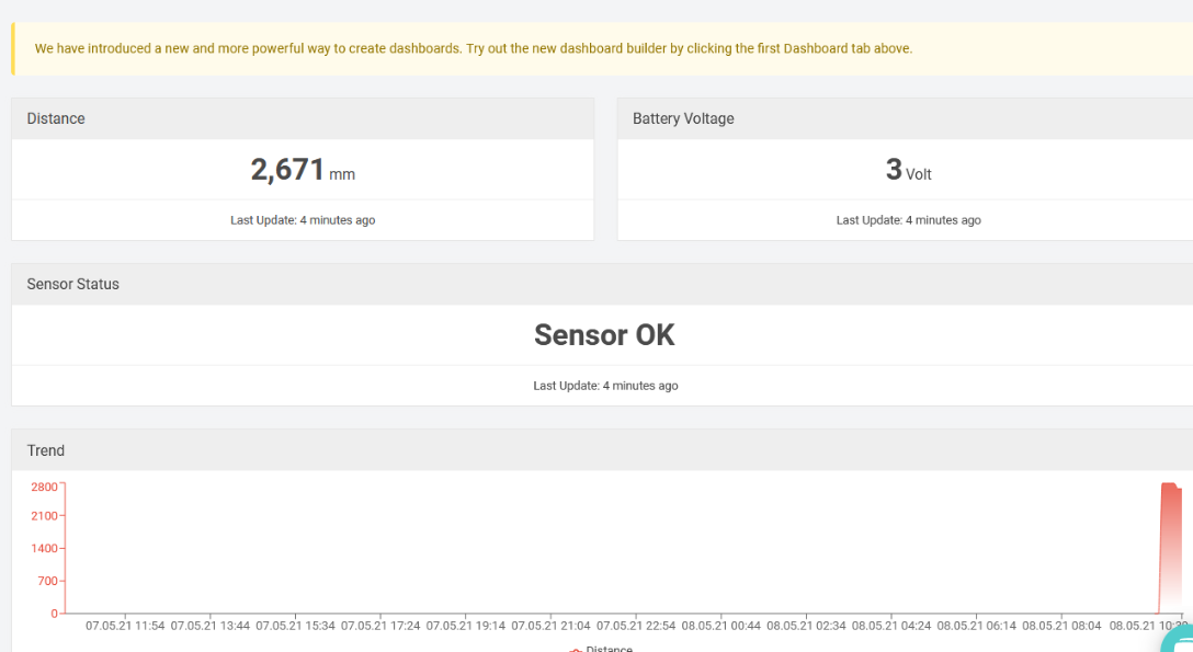
After added, the sensor data arrive TTN V3, it will also arrive and show in Datacake.
2.6 LED Indicator
The LDDS20 has an internal LED which is to show the status of different state.
- Blink once when device power on.
- The device detects the sensor and flashes 5 times.
- Solid ON for 5 seconds once device successful Join the network.
- Blink once when device transmit a packet.
2.7 Firmware Change Log
Firmware download link: http://www.dragino.com/downloads/index.php?dir=LoRa_End_Node/LSE01/Firmware/
Firmware Upgrade Method: Firmware Upgrade Instruction
2.8 Battery Analysis
2.8.1 Battery Type
The LDDS20 battery is a combination of a 8500mAh Li/SOCI2 Battery and a Super Capacitor. The battery is non-rechargeable battery type with a low discharge rate (<2% per year). This type of battery is commonly used in IoT devices such as water meter.
The battery related documents as below:
2.8.2 Battery Note
The Li-SICO battery is designed for small current / long period application. It is not good to use a high current, short period transmit method. The recommended minimum period for use of this battery is 5 minutes. If you use a shorter period time to uplink data, then the battery life may be decreased.
2.8.3 Replace the battery
You can change the battery in the LDDS75.The type of battery is not limited as long as the output is between 3v to 3.6v. On the main board, there is a diode (D1) between the battery and the main circuit. If you need to use a battery with less than 3.3v, please remove the D1 and shortcut the two pads of it so there won't be voltage drop between battery and main board.
The default battery pack of LDDS75 includes a ER18505 plus super capacitor. If user can't find this pack locally, they can find ER18505 or equivalence, which will also work in most case. The SPC can enlarge the battery life for high frequency use (update period below 5 minutes)
2.8.4 Battery Life Analyze
Dragino battery powered products are all run in Low Power mode. User can check the guideline from this link to calculate the estimate battery life:
3. Using the AT Commands
3.1 Access AT Commands
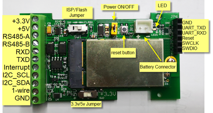
LDDS20 supports AT Command set in the stock firmware. You can use a USB to TTL adapter to connect to LDDS20 for using AT command, as below.
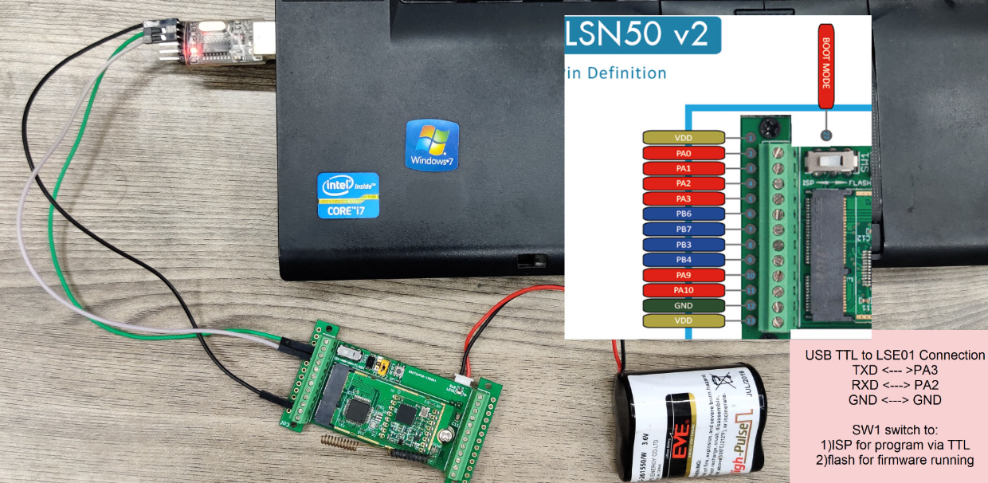
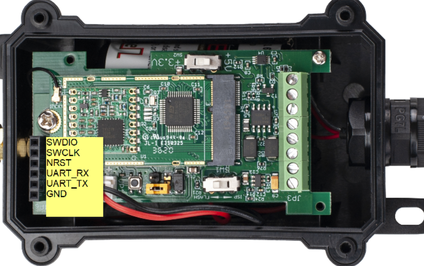
Or if you have below board, use below connection:
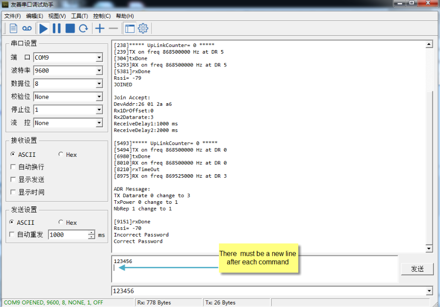
In the PC, you need to set the serial baud rate to 9600 to access the serial console for LDDS20. LDDS20 will output system info once power on as below:
Below are the available commands, a more detailed AT Command manual can be found at AT Command Manual.
AT+<CMD>? : Help on <CMD>
AT+<CMD> : Run <CMD>
AT+<CMD>=<value> : Set the value
AT+<CMD>=? : Get the value
General Commands :
AT : Attention
AT? : Short Help
ATZ : MCU Reset
AT+TDC : Application Data Transmission Interval
Keys, IDs and EUIs management :
AT+APPEUI : Application EUI
AT+APPKEY : Application Key
AT+APPSKEY : Application Session Key
AT+DADDR : Device Address
AT+DEUI : Device EUI
AT+NWKID : Network ID (You can enter this command change only after successful network connection)
AT+NWKSKEY : Network Session Key Joining and sending date on LoRa network
AT+CFM : Confirm Mode
AT+CFS : Confirm Status
AT+JOIN : Join LoRa? Network
AT+NJM : LoRa? Network Join Mode
AT+NJS : LoRa? Network Join Status
AT+RECV : Print Last Received Data in Raw Format
AT+RECVB : Print Last Received Data in Binary Format
AT+SEND : Send Text Data
AT+SENB : Send Hexadecimal Data
LoRa Network Management :
AT+ADR : Adaptive Rate
AT+CLASS : LoRa Class(Currently only support class A
AT+DCS : Duty Cycle Setting
AT+DR : Data Rate (Can Only be Modified after ADR=0)
AT+FCD : Frame Counter Downlink
AT+FCU : Frame Counter Uplink
AT+JN1DL : Join Accept Delay1
AT+JN2DL : Join Accept Delay2
AT+PNM : Public Network Mode
AT+RX1DL : Receive Delay1
AT+RX2DL : Receive Delay2
AT+RX2DR : Rx2 Window Data Rate
AT+RX2FQ : Rx2 Window Frequency
AT+TXP : Transmit Power
Information :
AT+RSSI : RSSI of the Last Received Packet
AT+SNR : SNR of the Last Received Packet
AT+VER : Image Version and Frequency Band
AT+FDR : Factory Data Reset
AT+PORT : Application Port
AT+CHS : Get or Set Frequency (Unit: Hz) for Single Channel Mode
AT+CHE : Get or Set eight channels mode, Only for US915, AU915, CN470
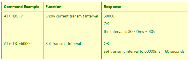
3.2 Set Transmit Interval Time
Feature: Change LoRaWAN End Node Transmit Interval.
AT Command: AT+TDC
Downlink Command: 0x01
Format: Command Code (0x01) followed by 3 bytes time value.
If the downlink payload=0100003C, it means set the END Node’s Transmit Interval to 0x00003C=60(S), while type code is 01.
- Example 1: Downlink Payload: 0100001E // Set Transmit Interval (TDC) = 30 seconds
- Example 2: Downlink Payload: 0100003C // Set Transmit Interval (TDC) = 60 seconds
3.3 Set Interrupt Mode
Feature, Set Interrupt mode for GPIO_EXIT.
Downlink Command: AT+INTMOD
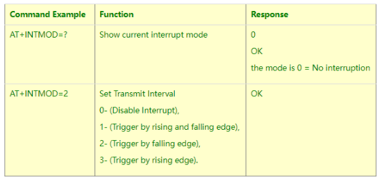
Downlink Command: 0x06
Format: Command Code (0x06) followed by 3 bytes.
This means that the interrupt mode of the end node is set to 0x000003=3 (rising edge trigger), and the type code is 06.
- Example 1: Downlink Payload: 06000000 // Turn off interrupt mode
- Example 2: Downlink Payload: 06000003 // Set the interrupt mode to rising edge trigger
4. FAQ
4.1 What is the frequency plan for LDDS75?
LDDS75 use the same frequency as other Dragino products. User can see the detail from this link: Introduction
4.2 How to change the LoRa Frequency Bands/Region
You can follow the instructions for how to upgrade image.
When downloading the images, choose the required image file for download.
4.3 Can I use LDDS75 in condensation environment?
LDDS75 is not suitable to be used in condensation environment. Condensation on the LDDS75 probe will affect the reading and always got 0.
5. Trouble Shooting
5.1 Why I can’t join TTN V3 in US915 / AU915 bands?
It is due to channel mapping. Please see below link: Frequency band
5.2 AT Command input doesn't work
In the case if user can see the console output but can’t type input to the device. Please check if you already include the ENTER while sending out the command. Some serial tool doesn’t send ENTER while press the send key, user need to add ENTER in their string.
6. Order Info
Part Number : LDDS75-XX-YY
XX: The default frequency band
- AS923 : LoRaWAN AS923 band
- AU915 : LoRaWAN AU915 band
- EU433 : LoRaWAN EU433 band
- EU868 : LoRaWAN EU868 band
- KR920 : LoRaWAN KR920 band
- US915 : LoRaWAN US915 band
- IN865 : LoRaWAN IN865 band
- CN470 : LoRaWAN CN470 band
YY: Battery Option
- 4 : 4000mAh battery
- 8 : 8500mAh battery
7. Packing Info
Package Includes:
- LDDS75 LoRaWAN Distance Detection Sensor x 1
Dimension and weight:
- Device Size: cm
- Device Weight: g
- Package Size / pcs : cm
- Weight / pcs : g
8. Support
- Support is provided Monday to Friday, from 09:00 to 18:00 GMT+8. Due to different timezones we cannot offer live support. However, your questions will be answered as soon as possible in the before-mentioned schedule.
- Provide as much information as possible regarding your enquiry (product models, accurately describe your problem and steps to replicate it etc) and send a mail to support@dragino.com.