WSC3-L -- Weather Station Kit User Manual

Table of Contents:
- 1. Introduction
- 2. How to use
- 3. Configure WSC3-L
- 4. Power consumption & Battery
- 6. OTA Firmware update
- 7. FAQ
- 8. Trouble Shooting
- 9. Order Info
- 10. Packing Info
- 11. Support
1. Introduction
1.1 Overview
The Dragino Weather Station Kit is designed for measuring atmospheric conditions to provide information for weather forecasts and to study the weather and climate.
The Weather Station Kit includes a LoRaWAN transmitter WSC3-L, an interrupting rain gauge and a 3-in-1 sensor and a light sensor.
Please note that the WSC3-L only includes the transmitter, the 3-in-1 sensor and the interrupting rain gauge and light sensor need to be purchased separately.
The 3-in-1 sensor can measure the following values: Temperature, Humidity, Air pressure.
The LoRaWAN transmitter uses an I2C interface to communicate with the weather station sensor. It also has a pulse count input that can be used to connect a tipping bucket Rain Gauge.
WSC3-L is full compatible with LoRaWAN Class A protocol, it can work with standard LoRaWAN gateway.
1.2 Features & Spec for WSC3-L Transmitter
- LoRaWAN 1.0.3 Class A
- Bands: CN470/EU433/KR920/US915/EU868/AS923/AU915/IN865
- Ultra-low power consumption
- Support interrupt rain gauge
- Support Bluetooth v5.1 and LoRaWAN remote configure
- Support wireless OTA update firmware
- AT Commands to change parameters
- Downlink to change configure
- IP66 Waterproof Enclosure
- 3000mAh Rechargeable Li-ion Battery
1.3 Specification for 3-in-1 sensors

Temperature:
- Range: -20 to + 80°C
- Accuracy: ±0.2 @ 0-90 °C
- Resolution: 0.1°C
- Long Term Shift: <0.03 °C/yr
Humidity:
- Range: 0 ~ 99.9% RH
- Accuracy: ± 2%RH ( 0 ~ 100%RH)
- Resolution: 0.01% RH
- Long Term Shift: <0.25 %RH/yr
Air Pressure:
- Accuracy: ±0.15kPa@25°C 101kPa
- Range: 300~1100hPa
1.4 illuminace Sensor
- Base on BH1750 Illumination Sensor
- Cable Length : 50cm
- Resolution: 1 lx
- Range: 0-65535 lx
- Operating Range: -40 °C ~ 85 °C
1.5 Sleep mode and working mode
Deep Sleep Mode: Sensor doesn't have any LoRaWAN activate. This mode is used for storage and shipping to save battery life.
Working Mode: In this mode, Sensor will work as LoRaWAN Sensor to Join LoRaWAN network and send out sensor data to server. Between each sampling/tx/rx periodically, sensor will be in IDLE mode), in IDLE mode, sensor has the same power consumption as Deep Sleep mode.
1.6 Button & LEDs
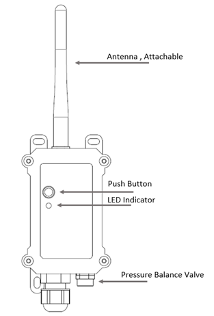
| Behavior on ACT | Function | Action |
|---|---|---|
| Pressing ACT between 1s < time < 3s | Send an uplink | If sensor is already Joined to LoRaWAN network, sensor will send an uplink packet, blue led will blink once. |
| Pressing ACT for more than 3s | Active Device | Green led will fast blink 5 times, device will enter OTA mode for 3 seconds. And then start to JOIN LoRaWAN network. |
| Fast press ACT 5 times. | Deactivate Device | Red led will solid on for 5 seconds. Means device is in Deep Sleep Mode. |
1.7 BLE connection
WSC3-L supports BLE remote configure.
BLE can be used to configure the parameter of sensor or see the console output from sensor. BLE will be only activate on below case:
- Press button to send an uplink
- Press button to active device.
- Device Power on or reset.
If there is no activity connection on BLE in 60 seconds, sensor will shut down BLE module to enter low power mode.
1.8 Pin Mapping

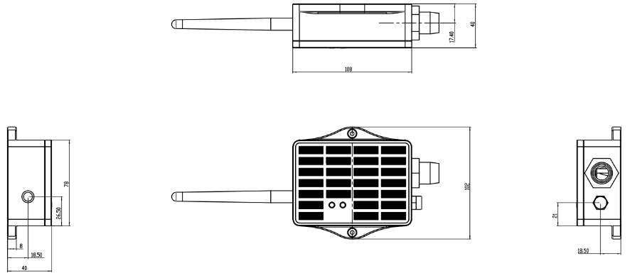
1.9 Mechanical(for LS version)
2. How to use
2.1 How it works?
Each WSC3-L is shipped with a worldwide unique set of OTAA keys. To use WSC3-L in a LoRaWAN network, user needs to input the OTAA keys in LoRaWAN network server. After finish installation as above. Create WSC3-L in your LoRaWAN server and Power on WSC3-L , it can join the LoRaWAN network and start to transmit sensor data. The default period for each uplink is 20 minutes.
2.2 Example to use for LoRaWAN network(OTAA)
This section shows an example for how to join the TTN V3 LoRaWAN IoT server. Usages with other LoRaWAN IoT servers are of similar procedure.
Assume the DLOS8 is already set to connect to TTN V3 network . We need to add the WSC3-L device in TTN V3:
Step 1: Create a device in TTN V3 with the OTAA keys from WSC3-L.
Each WSC3-L is shipped with a sticker with the default device EUI as below:

User can enter these keys in the LoRaWAN Server portal. Below is TTN V3 screen shot:
Create the application.


Add devices to the created Application.


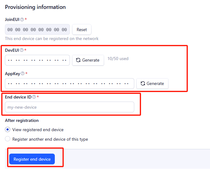
Enter end device specifics manually.

Add DevEUI and AppKey. Customize a platform ID for the device.

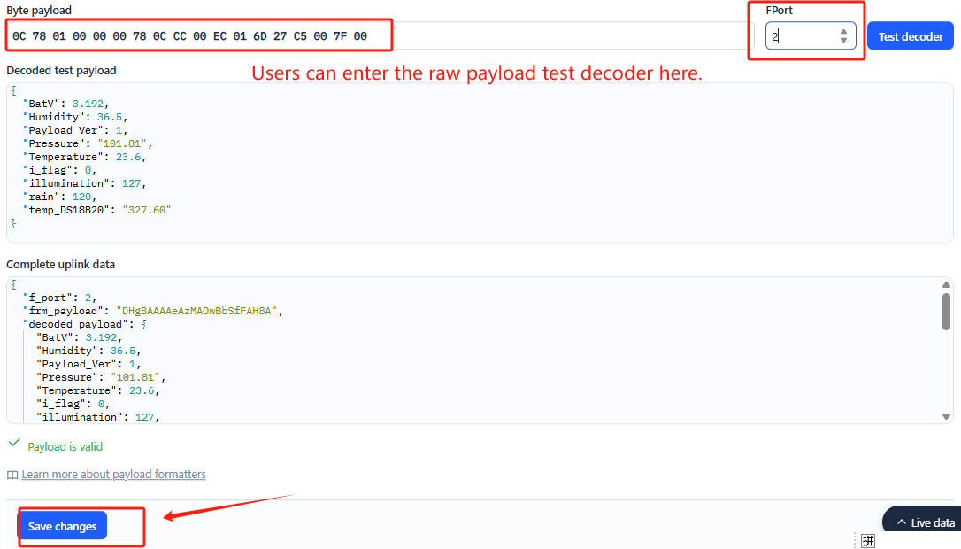
Step 2: Add decoder
In TTN, user can add a custom payload so it shows friendly reading.
Click this link to get the decoder: https://github.com/dragino/dragino-end-node-decoder/tree/main/
Below is TTN screen shot:

Step 3: Activate on WSC3-L
Press the button for 5 seconds to activate the WSC3-L.
Green led will fast blink 5 times, device will enter OTA mode for 3 seconds. And then start to JOIN LoRaWAN network.
Green led will solidly turn on for 5 seconds after joined in network.
After join success, it will start to upload messages to TTN and you can see the messages in the panel.
2.3 Uplink Payload
Uplink payloads include two types: Valid Sensor Value and other status / control command.
- Valid Sensor Value: Use FPORT=2
- Other control command: Use FPORT other than 2.
2.3.1 Uplink FPORT=5, Device Status
Users can use the downlink command(0x26 01) to ask WSC3-L to send device configure detail, include device configure status. WSC3-L will uplink a payload via FPort=5 to server.
The Payload format is as below.
| Device Status(FPORT=5) | |||||
|---|---|---|---|---|---|
| Size(bytes) | 1 | 2 | 1 | 1 | 2 |
| Value | Sensor Model | Firmware Version | Frequency Band | Sub-band | BAT |
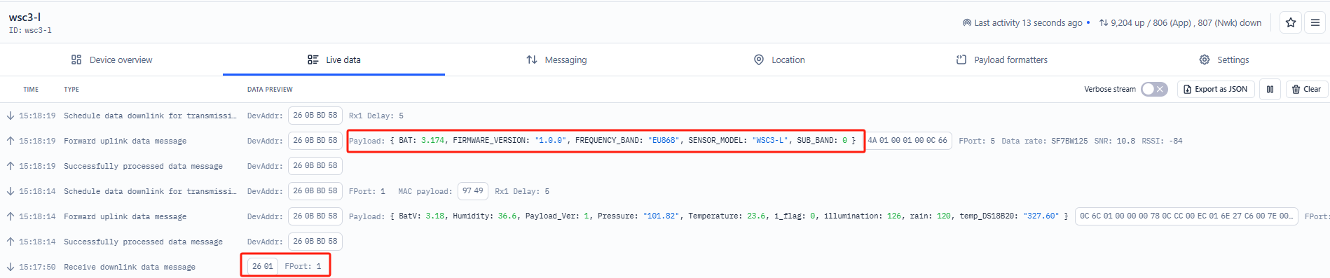
Sensor Model:For WSC3-L, this value is 0x4A.
Firmware Version:0x0100, Means: v1.0.0 version.
Frequency Band:
0x01: EU868
0x02: US915
0x03: IN865
0x04: AU915
0x05: KZ865
0x06: RU864
0x07: AS923
0x08: AS923-1
0x09: AS923-2
0x0a: AS923-3
Sub-Band:
AU915 and US915:value 0x00 ~ 0x08
CN470: value 0x0B ~ 0x0C
Other Bands: Always 0x00
Battery Info:
shows the battery voltage for WSC3-L MCU.
Ex1: 0x0C66/1000 = 3174/1000=3.174V
Users can also use the downlink command (0x23 01) to change the uplink port of WSC3-L:
Example Downlink:0x23 01(Change to port 1)

2.3.2 Uplink FPORT=2, Real time sensor value
WSC3-L will send this uplink after Device Config uplink once join LoRaWAN network successfully. And it will periodically send this uplink. Default interval is 20 minutes and can be changed.
Uplink uses FPORT=2 and every 20 minutes send one uplink by default.
Size(bytes) | 2 | 1 | 3 | 2 | 2 | 2 | 2 | 2 | 1 |
|---|---|---|---|---|---|---|---|---|---|
| Value | Battery | Payload _ver | Rain | temp_ DS18B20 | Temperature | Humidity | Pressure | illumination | i_flag |
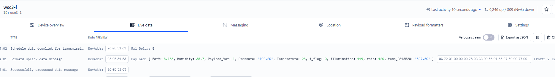
Battery
Sensor Battery Level.
Ex1: 0x0C72 = 3186mV
Ex2: 0x0B49 = 2889mV
Temperature
Example:
If payload is: 0105H: (0105 & 8000 == 0), temp = 0105H /10 = 26.1 degree
If payload is: FF3FH : (FF3F & 8000 == 1) , temp = (FF3FH - 65536)/10 = -19.3 degrees.
(FF3F & 8000:Judge whether the highest bit is 1, when the highest bit is 1, it is negative)
Humidity
Example:
0x(0199) = 409 Value: 409 / 10=40.9, So 40.9%
Pressure
Example:
0x(27ED) = 10221 Value: 10221/100 = 102.21Pa
illumination
Example:
0x(0097) = 151 Lux
2.4 Unix TimeStamp
WSC3-L uses Unix TimeStamp format based on
Users can get this time from the link: https://www.epochconverter.com/
Below is the converter example

So, we can use AT+TIMESTAMP=1742278702 or downlink 3067D9102E to set current time : March 18, 2025 06:18:22
2.5 Set Device Time
There are two ways to set the device's time:
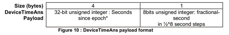
1. Through LoRaWAN MAC Command (Default settings)
Users need to set SYNCMOD=1 to enable sync time via the MAC command.
Once WSC3-L Joined LoRaWAN network, it will send the MAC command (DeviceTimeReq) and server will reply with (DeviceTimeAns) to send the current time to WSC3-L. If WSC3-L fails to get the time from server, WSC3-L will use the internal time and wait for next time request (AT+SYNCTDC to set time request period, default is 10 days).
Note: LoRaWAN Server needs to support LoRaWAN v1.0.3(MAC v1.0.3) or higher to support this MAC command feature, Chirpstack,TTN v3 and loriot support but TTN v2 doesn't support. If server doesn't support this command, it will through away uplink packet with this command, so user will lose the packet with time request for TTN v2 if SYNCMOD=1.
2. Manually Set Time
Users need to set SYNCMOD=0 to manual time, otherwise, the user set time will be overwritten by the time set by the server.
2.6 Frequency Plans
The WSC3-L uses OTAA mode and below frequency plans by default. Each frequency band use different firmware, user update the firmware to the corresponding band for their country.
http://wiki.dragino.com/xwiki/bin/view/Main/End%20Device%20Frequency%20Band/
3. Configure WSC3-L
3.1 Configure Methods
WSC3-L supports below configure method:
- AT Command via Bluetooth Connection (Recommended): BLE Configure Instruction.
- AT Command via UART Connection : See UART Connection.
- LoRaWAN Downlink. Instruction for different platforms: See IoT LoRaWAN Server section.
3.2 Serial Access Password
After the Bluetooth or UART connection is successful, use the Serial Access Password to enter the AT command window.
The label on the box of the node will print the initial password: AT+PIN=xxxxxx, and directly use the six-digit password to access the AT instruction window.
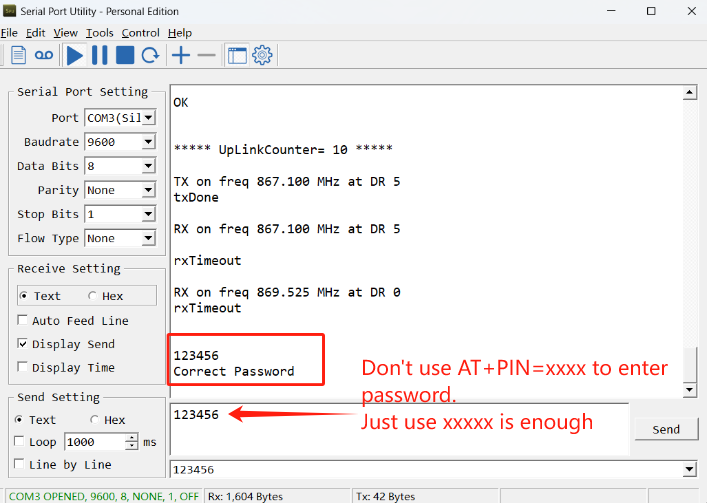
If you need to change the password, use AT+PWORD=xxxxxx (6 characters)
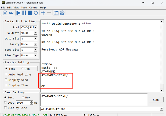
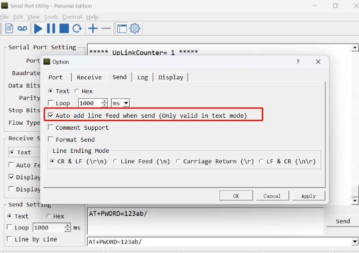
Note: After entering the command, you need to add a line break, and you can also set automatic line breaks in the Bluetooth tool or UART connection tool.
3.3 General Commands
These commands are to configure:
- General system settings like: uplink interval.
- LoRaWAN protocol & radio related command.
They are same for all Dragino Devices which support DLWS-005 LoRaWAN Stack. These commands can be found on the wiki:
http://wiki.dragino.com/xwiki/bin/view/Main/End%20Device%20AT%20Commands%20and%20Downlink%20Command/
3.4 Commands special design for WSC3-L
These commands only valid for WSC3-L, as below:
3.4.1 Set Transmit Interval Time
Feature: Change LoRaWAN End Node Transmit Interval.
AT Command: AT+TDC
| Command Example | Function | Response |
| AT+TDC=? | Show current transmit Interval | 30000 |
| AT+TDC=60000 | Set Transmit Interval | OK |
Downlink Command: 0x01
Format: Command Code (0x01) followed by 3 bytes time value.
If the downlink payload=0100003C, it means set the END Node's Transmit Interval to 0x00003C=60(S), while type code is 01.
- Example 1: Downlink Payload: 0100001E // Set Transmit Interval (TDC) = 30 seconds
- Example 2: Downlink Payload: 0100003C // Set Transmit Interval (TDC) = 60 seconds
3.4.2 Set Interrupt Mode
Feature, Set Interrupt mode for GPIO_EXIT of pin.
When AT+INTMOD=0 is set, GPIO_EXIT is used as a digital input port.
AT Command: AT+INTMOD
| Command Example | Function | Response |
|---|---|---|
| AT+INTMOD=? | Show current interrupt mode | 0 |
| AT+INTMOD=2 | Set Transmit Interval | OK |
Downlink Command: 0x06
Format: Command Code (0x06) followed by 3 bytes.
This means that the interrupt mode of the end node is set to 0x000003=3 (rising edge trigger), and the type code is 06.
- Example 1: Downlink Payload: 06000000 // Turn off interrupt mode
- Example 2: Downlink Payload: 06000003 // Set the interrupt mode to rising edge trigger
3.4.3 Set or get the total count value
Feature: The user can set the counting to start from the set value according to the requirements. (only available in counting mode).
AT Command:
| Command Example | Function | Response |
|---|---|---|
| AT+SETCNT=1000 | Set the total count to start from 1000 | OK |
Downlink Command:
Format: Command Code (0x09) followed by 5 bytes time value.
If the downlink payload=09000003E8, This means that the count of the END node will start counting from setting 0x000003E8=1000 (times). while type code is 09.
- Example 1: Downlink Payload: 09000003E8 // Set the value to start counting from 1000 = 1000 (times)
3.4.4 Set interrupt or counting mode
Feature: Users can set the trigger mode to counting mode or interrupt mode as needed.
AT Command:
| Command Example | Function | Response |
|---|---|---|
| AT+COUNTMOD=0 | set to interrupt mode | OK |
| AT+COUNTMOD=1 | set to counting mode | OK |
Downlink Command:
Format: Command Code (0x10) followed by 1 bytes time value.
If the downlink payload=10 00, Set the trigger mode to interrupt mode, while type code is 10.
- Example 1: Downlink Payload: 10 00 // Same as: AT+COUNTMOD=0 set to interrupt mode
3.4.5 Set time synchronization method
Feature: This command is used to enable automatic time calibration by time zone(Get or Set time synchronization method).
AT Command: AT+SYNCMOD
| Command Example | Function | Response/Parameter |
|---|---|---|
AT+SYNCMOD=? | Get the current time synchronization method | 1,0 (Default) OK |
| AT+SYNCMOD=aa,bb | aa: Enable/disable automatic time zone calibration | 0: Disable automatic time zone calibration. 1: Enable automatic time zone calibration |
| bb: Set the time zone: -12 ~ 12 | Negative number: West Time Zone Positive number: Eastern Time Zone |
Downlink Command: 0x28
Format: Command Code (0x28) followed by 2 bytes.
- Example 1: Downlink Payload: 28 00 00 // Turn off the time zone calibration time.
- Example 2: Downlink Payload: 28 01 FA // Turn on time zone calibration time, UTC-6
- Example 3: Downlink Payload: 28 01 06 // Turn on time zone calibration time, UTC+6
Note: UTC-6: 256+(-6)=250(D)=0xFA(H)
3.4.6 Set time synchronization interval
Feature: Get or set time synchronization interval in day or hour.
AT Command: AT+SYNCTDC
| Command Example | Function | Response/Parameter |
|---|---|---|
AT+SYNCTDC=? | Gets the current time synchronization interval | 12,1 (Default) OK |
AT+SYNCTDC=aa,bb | aa: Set the interval for automatic synchronization | Range: 0~255 |
| bb: Set the unit of the time synchronization interval | 0: Unit: day 1: Unit: hour |
Downlink Command: 0x29
Format: Command Code (0x29) followed by 3 bytes.
- Example 1: Downlink Payload: 29 0C 00 // Calibrate once every 12 days
- Example 2: Downlink Payload: 29 0C 01 // Calibrate once every 12 hours
4. Power consumption & Battery
The WSC3-L uses a 3000mAh lithium battery and a solar panel. For battery information and details on how to replace the battery, see the following links:
AI Calculation Battery Life Instructions
Here are the currents and durations of the WSC3-L device for different transmission rates:

6. OTA Firmware update
User can change firmware WSC3-L to:
- Change Frequency band/ region.
- Update with new features.
- Fix bugs.
Firmware and changelog can be downloaded from : Firmware download link
Methods to Update Firmware:
- (Recommanded way) OTA firmware update via wireless: http://wiki.dragino.com/xwiki/bin/view/Main/Firmware%20OTA%20Update%20for%20Sensors/
- Update through UART TTL interface: Instruction.
7. FAQ
8. Trouble Shooting
8.1 Why does the rain gauge have no data?
The default mode of the rain gauge is trigger mode.
When it rains, it will trigger an uplink, and the data does not include rainfall data.
If you want to query rainfall data, please change to counting mode
Feature: Users can set the trigger mode to counting mode or interrupt mode as needed.
AT Command:
| Command Example | Function | Response |
|---|---|---|
| AT+COUNTMOD=0 | set to interrupt mode | OK |
| AT+COUNTMOD=1 | set to counting mode | OK |
Downlink Command:
Format: Command Code (0x10) followed by 1 bytes time value.
If the downlink payload=10 00, Set the trigger mode to interrupt mode, while type code is 10.
- Example 1: Downlink Payload: 10 00 // Same as: AT+COUNTMOD=0 set to interrupt mode
9. Order Info
Part Number: WSC3-L-XX
XX: The default frequency band
- AS923: LoRaWAN AS923 band
- AU915: LoRaWAN AU915 band
- EU433: LoRaWAN EU433 band
- EU868: LoRaWAN EU868 band
- KR920: LoRaWAN KR920 band
- US915: LoRaWAN US915 band
- IN865: LoRaWAN IN865 band
- CN470: LoRaWAN CN470 band
10. Packing Info
Packing Includes:
- WSC3-L LoRaWAN Weather Station Sensor
Dimension and weight:
- Device Size: cm
- Device Weight: g
- Package Size / pcs : cm
- Weight / pcs : g
11. Support
- Support is provided Monday to Friday, from 09:00 to 18:00 GMT+8. Due to different timezones we cannot offer live support. However, your questions will be answered as soon as possible in the before-mentioned schedule.
- Provide as much information as possible regarding your enquiry (product models, accurately describe your problem and steps to replicate it etc) and send a mail to support@dragino.com.