PB05-L -- LoRaWAN Button User Manual

Table of Contents:
- 1. Introduction
- 2. Operation Mode
- 3. Configure PB05-L via AT command or LoRaWAN downlink
- 4. Battery & How to replace
- 5. OTA Firmware update
- 6. Use Cases
- 7. FAQ
- 8. Order Info
- 9. Packing Info
- 10. Support
1. Introduction
1.1 What is the PB05-L LoRaWAN Push Button?
The PB05-L LoRaWAN Button is a wireless device with 5 push buttons. When a button is pressed, the device sends a signal to the IoT server using the LoRaWAN protocol.
It runs on 2 x AA batteries, lasting for approximately 30k presses across all five buttons. When the batteries run out, they can be easily replaced.
The PB05-L also has a built-in speaker that plays different sounds when a button is pressed or when a response is received from the server. If needed, the speaker can be turned off.
This device is fully compatible with LoRaWAN v1.0.3 and works with any standard LoRaWAN gateway.
1.2 Features
- Wall-mountable
- LoRaWAN v1.0.3 Class A protocol
- 5 push buttons
- Built-in speaker
- Frequency bands: CN470, EU433, KR920, US915, EU868, AS923, AU915
- AT commands for parameter configuration
- Remote parameter configuration via LoRaWAN downlink
- Firmware upgradeable via programming port
- Supports 2 × AA LR6 batteries
- IP52-rated for dust and water resistance
1.3 Power Consumption
- Idle: 5 µA
- Transmit: Max 110 mA
1.4 Storage & Operation Temperature
-10 ~ 50 °C or -40 ~ 60 °C (depends on the battery type, see FAQ)
1.5 Applications
- Smart Buildings & Home Automation
- Logistics and Supply Chain Management
- Smart Metering
- Smart Agriculture
- Smart Cities
- Smart Factory
See Use Cases (Section 7) for more information.
1.6 Device appearance

Note: For customization purposes, the PVC sticker is not attached by default.
1.7 Mechanical Drawings

2. Operation Mode
2.1 How does it work?
Each PB05-L is shipped with a unique set of LoRaWAN registration information, including DevEUI, AppEUI, and AppKey. To use the PB05-L in a LoRaWAN network, the user must register these EUIs and keys in advance to enable OTAA activation of the device in the LoRaWAN network server.

Once the device is powered on and within the network’s coverage, it will automatically join and start transmitting sensor data. By default, it sends an uplink every 20 minutes.
2.2 How to Activate PB05-L?
1. Open the enclosure from the bottom as shown in the image below.

2. Insert 2 x AA LR6 batteries. Make sure to insert them in the correct direction.

3. Activate the device by pressing and holding (long press) the ACT button.

You can check LED Status to determine the working state of the PB05-L.
2.3 Joining with a LoRaWAN network server
This section shows an example of how to join The Things Stack LoRaWAN network server. Registering with other LoRaWAN network servers may also follow a similar procedure.
The following network diagram shows that the PB05-L is connected to a LoRaWAN Network Server. The network server supports end-to-end data communication between the PB05-L and the application server. You can use any public LoRaWAN Network Server to register your device, or you can set up your own private LoRaWAN Network Server. The Things Stack (both free and paid) and ChirpStack are some of the popular LoRaWAN Network Servers available for use.
The following network diagram illustrates how the PB05-L connects to a LoRaWAN network server and how end-to-end communication occurs between the PB05-L and the application server.
The PB01-L sends LoRa-modulated uplink packet when a specific button (Button 1 to 5) is pressed by the user. The uplink packet is received by the LoRaWAN gateway and forwarded to the LoRaWAN Network Server via its internet connection. The Network Server then forwards the application payload of the uplink packet to the Application Server for further processing, enabling data analysis and valuable insights. Both the Application Server and the Network Server can send downlink messages to the PB05-L through the LoRaWAN gateway.

2.3.1 Registering with The Things Stack
The following steps guide you through the process of registering the PB05-L with The Things Stack LoRaWAN network server.
2.3.1.1 Setting up
- Sign up for a free account with The Things Stack Sandbox if you do not have one yet.
- Log in to your The Things Stack account.
- Create an application with The Things Stack if you do not have one yet.
- On the left navigation, click Applications.
- Then click + Add Application button.
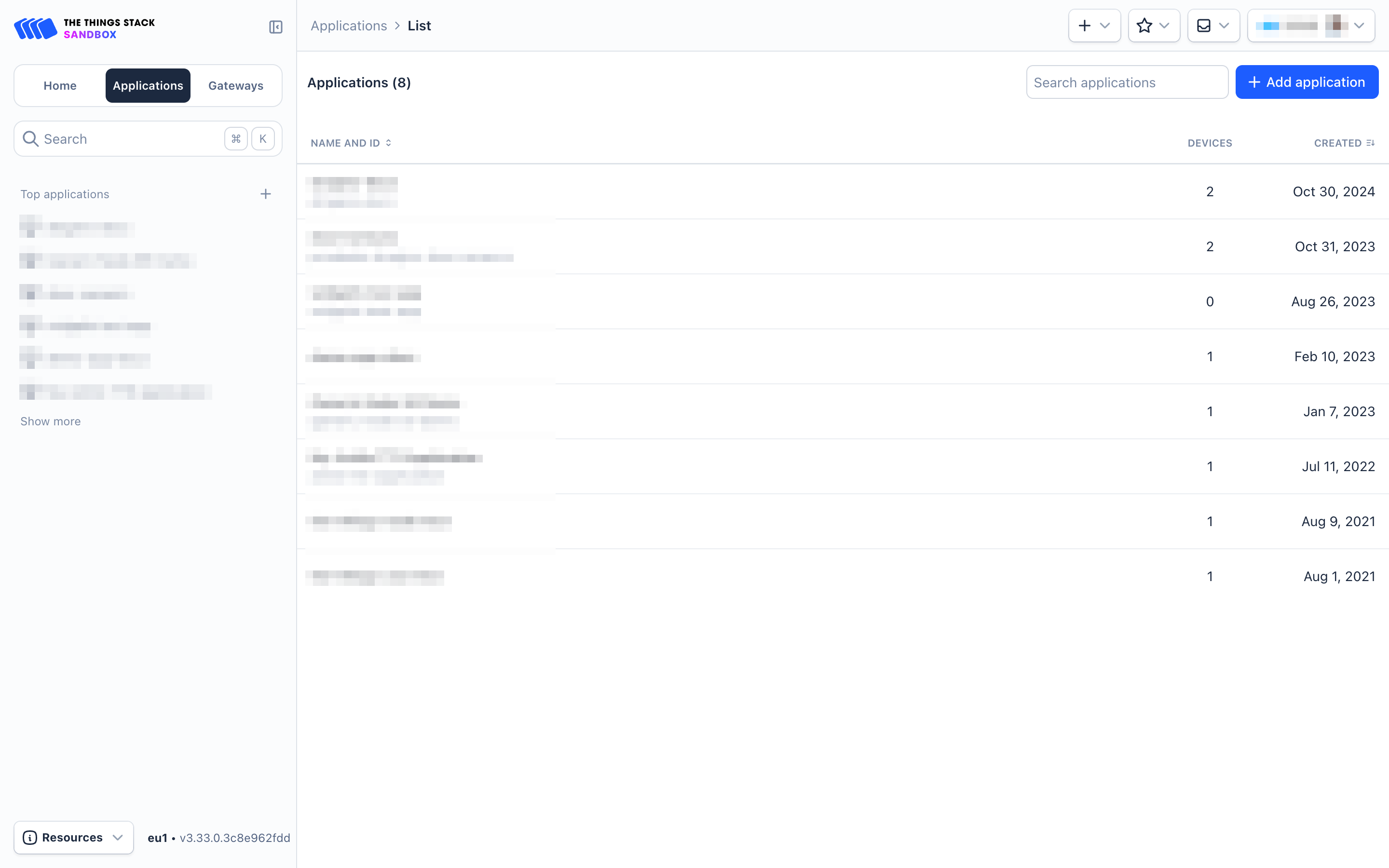
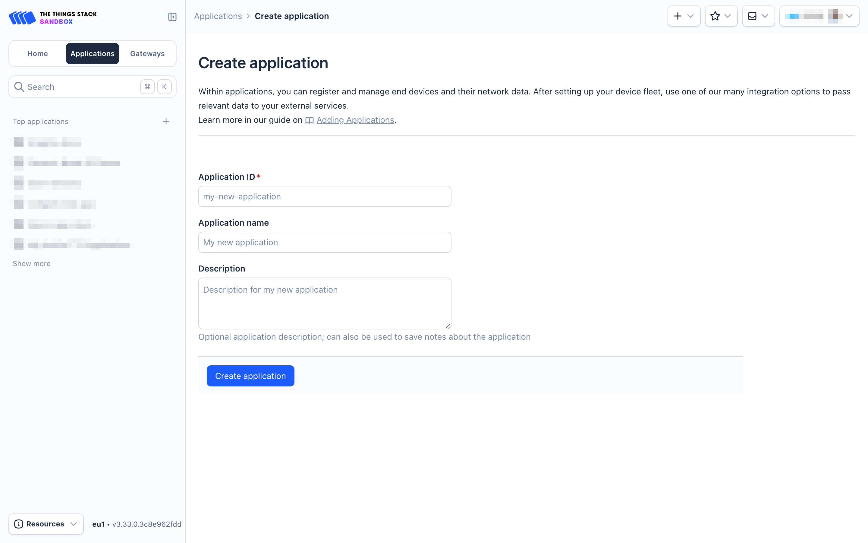
- On the Create Application page, configure the following:
- Application ID: Provide a unique identification for your application within The Things Stack.
- Application name: (optional) Provide a descriptive name.
- Description: (optional) Provide a description.
- Click on Create application button.
- Go to your application's page and click on the End devices in the left menu.
- On the End devices page, click on + Register end device.

- Two registration options are available:
- Using the LoRaWAN Device Repositoty
- Manual registration
2.3.1.2 Manual registration
Currently, the PB05-L supports only manual registration.
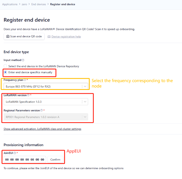
- On the Register end device page:
- Select the option Enter end device specifies manually under Input method.
- Select the Frequency plan that matches your device from the Frequency plan dropdown list.
- Select the LoRaWAN version as LoRaWAN Specification 1.0.3
- Select the Regional Parameters version as RP001 Regional Parameters 1.0.3 revision A
- Enter AppEUI in the JoinEUI field. Then click Confirm button.
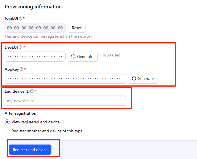
- In the DevEUI field, enter the DevEUI.
- In the AppKey field, enter the AppKey.
- In the End device ID field, enter a unique name for your PB05 within this application.
- Under After registration, select the View registered end device option.
- Click the Register end device button.
You will be navigated to the Device overview page.
2.3.1.3 Uplink Payload Formatter (Decoder)
To add the uplink formatter code, select Applications > [your application] > End devices > [your end device] > Payload formatters > Uplink. Then select Use Device repository formatters for the Formatter type dropdown. Click the Save changes button to apply the changes.
The uplink payload formatter for PB05-L can be downloaded from here: PB05-L decoder.

Press the ACT button to activate the PB05-L. It will then join The Things Stack. Once successfully joined, it will start uploading sensor data to The Things Stack, which you can view on the Live Data panel.

2.4 Uplink Payload
Uplink payloads include two types: Valid Sensor Value and Other Status / Control Commands.
- Valid Sensor Value: Use FPort=2
- Other Status / Control Commands: Use an FPort other than 2.
2.4.1 Uplink FPort=5, Device Status
You can get the Device Status uplink through the downlink command:
Downlink: 0x2601
The device uplinks the status using FPort=5.
| Size (bytes) | 1 | 2 | 1 | 1 | 2 |
|---|---|---|---|---|---|
| Value | Sensor Model | Firmware Version | Frequency Band | Sub-band | BAT |
Example from The Things Stack:
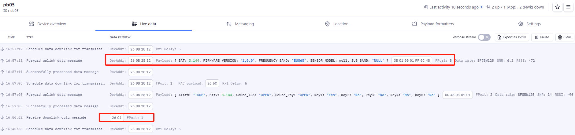
Example payload (FPort=5): ![]()
Sensor Model: For PB05-L, this value is 0x3B.
Firmware Version: 0x0100 means the version is v1.0.0.
Frequency Band:
- 0x01: EU868
- 0x02: US915
- 0x03: IN865
- 0x04: AU915
- 0x05: KZ865
- 0x06: RU864
- 0x07: AS923
- 0x08: AS923-1
- 0x09: AS923-2
- 0x0a: AS923-3
Sub-Band: Value 0x00 to 0x08 (only for CN470, AU915, and US915. For other regions, use 0x00.)
BAT: Shows the battery voltage of PB05-L.
Example: 0x0C48 = 3144mV
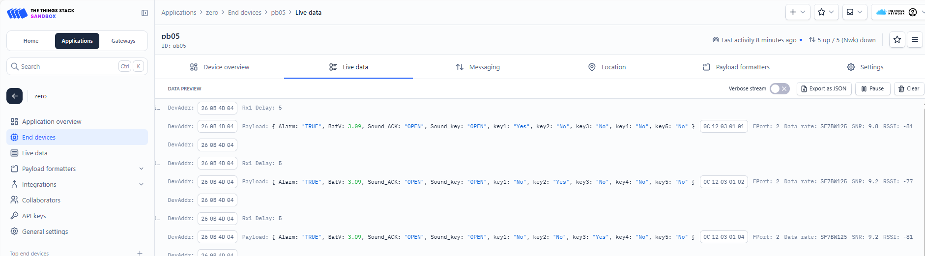
2.4.2 Uplink FPort=2, Real-time sensor value
The PB05-L will send this uplink after the Device Status uplink once it has successfully joined the LoRaWAN network. It will then continue to send this uplink periodically. The default interval is 20 minutes, but it can be changed.
This uplink uses FPort=2 and, by default, is sent once every 20 minutes.
Size(bytes) | 2 | 1 | 1 | 1 |
|---|---|---|---|---|
Value | Battery | Sound_key & Sound_ACK | Alarm | key1 & key2 & key3 & key4 & key5 |
key1 & key2 & key3 & key4 & key5:
| Size(bit) | bit[1:7] | bit0 |
|---|---|---|
Value | Reserve | key1 & key2 & key3 & key4 & key5 |
Example from The Things Stack.
Battery:
To get the battery voltage.
Example 1: 0x0CEA = 3306mV
Example 2: 0x0D08 = 3336mV
- Sound_key & Sound_ACK:
Key sound and ACK sound are enabled by default.
Example 1: 0x03
Sound_ACK: (03>>1) & 0x01=1, OPEN.
Sound_key: 03 & 0x01=1, OPEN.
Example 2: 0x01
Sound_ACK: (01>>1) & 0x01=0, CLOSE.
Sound_key: 01 & 0x01=1, OPEN.
- Alarm:
Key alarm.
Example 1: 0x01 & 0x01=1, "TRUE", key alarm packet.
Example 2: 0x00 & 0x01=0, "FALSE", normal uplink data.
- key1
Displays whether the uplink data was triggered by key 1.
01 (H): (0x01&0x01)=01(H) =0000 0001(B) bit0=1, "Yes"
02 (H): (0x02&0x01)=0 bit0=0, "No"
- key2
Displays whether the uplink data was triggered by key 2.
02 (H): (0x02>>1)&0x01 =01(H) =0000 0001(B) bit0=1, "Yes"
04 (H): (0x04>>1)&0x01 =0 bit0=0, "No"
- key3
Displays whether the uplink data was triggered by key 3.
04 (H): (0x04>>2)&0x01 =01(H) =0000 0001(B) bit0=1, "Yes"
08 (H): (0x08>>2)&0x01 =0 bit0=0, "No"
- key4
Displays whether the uplink data was triggered by key 4.
08 (H): (0x08>>3)&0x01 =01(H) =0000 0001(B) bit0=1, "Yes"
10 (H): (0x10>>3)&0x01 =0 bit0=0, "No"
- key5
Displays whether the uplink data was triggered by key 5.
10 (H): (0x10>>4)&0x01 =01(H) =0000 0001(B) bit0=1, "Yes"
01 (H): (0x01>>4)&0x01 =0 bit0=0, "No"
2.4.3 Uplink FPort=3, Datalog sensor value
PB05-L stores sensor values, and the user can retrieve this historical data via a downlink command. The datalogged sensor values are sent via FPort=3.
The historical payload includes one or multiple entries.
Size(bytes) | 4 | 1 | 1 | 1 | 4 |
|---|---|---|---|---|---|
Value | Reserve | key5 & key4 & key3 & key2 & key1 | Reserve | Poll message flag & alarm | Unix Time Stamp |
key5 & key4 & key3 & key2 & key1:
| Size(bit) | bit[1:7] | bit0 |
|---|---|---|
Value | Reserve | key5 & key4 & key3 & key2 & key1 |
Poll message flag & Alarm:
| Size(bit) | bit7 | bit6 | bit5 | bit4 | bit[3:1] | bit0 |
|---|---|---|---|---|---|---|
| Status&Ext | No ACK Message | Poll Message Flag | Sync time OK | Unix Time Request | Reserve | Alarm:1 |
No ACK Message: 1: This indicates that the payload is from an uplink message that did not receive an ACK from the server (related to the PNACKMD=1 feature)
Poll Message Flag: 1: This indicates that the message is a reply to a poll message.
- Each data entry is 11 bytes long to save airtime and battery. PB05-L will send the maximum number of bytes allowed based on the current data rate (DR) and frequency band.
For example, in the US915 band, the maximum payload size for different DRs is:
- DR0: Maximum is 11 bytes - the device sends one data entry.
- DR1: Maximum is 53 bytes - the device sends 4 data entries (44 bytes total).
- DR2: Payload includes 11 data entries.
- DR3: Payload includes 22 data entries.
If you send the downlink command: ![]()
Where:
Start time: 6722DD98 = 2024/10/31 (Thursday) 01:30:00
Stop time: 672300C0 = 2024/10/31 (Thursday) 04:00:00
PB05-L will uplink the following payload:
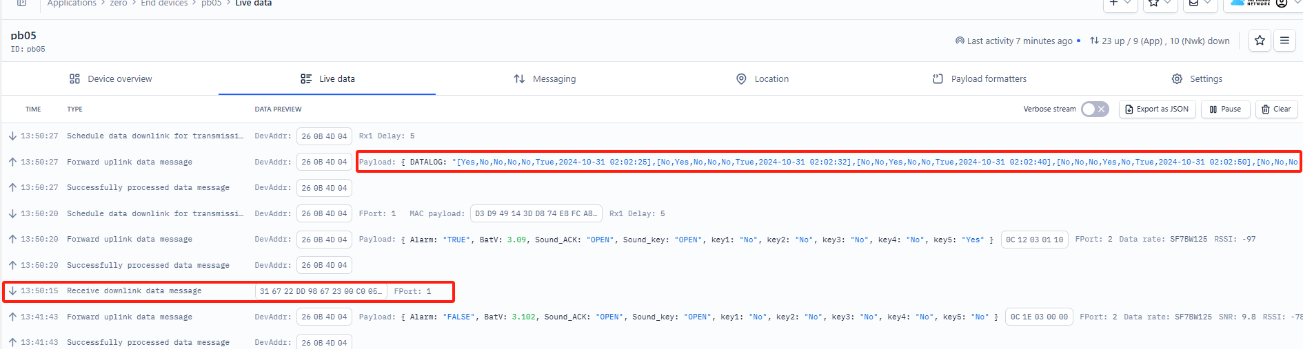
000000001000416722E531
000000000800416722E538000000000400416722E540000000000200416722E54A000000000100416722E552000000000000406722E9BA000000000000406722EE6A000000000000406722F31A000000000000406722F7CA000000001000416722F9BA000000001000416722F9F6000000000800416722FB0E000000000000406722FC7A
Where the first 11 bytes are for the first entry:
![]()
The first four bytes are reserved - (do not indicate anything)
key5 & key4 & key3 & key2 & key1: 10(H)
- key5: ((0x10>>4)&0x01) = 1, "Yes".
- key4: ((0x10>>3)&0x01) = 0, "No".
- key3: ((0x10>>2)&0x01) = 0, "No".
- key2: ((0x10>>2)&0x01) = 0, "No".
- key1: (0x10 & 0x01) = 0, "No".
The sixth byte is reserved - (does not indicate anything)
Poll Message Flag & Alarm: 0x41 (Hex) indicates a reply message. For the alarm, 0x41 & 0x01 = 1, which means "True."
Unix time is 0x6722E531= 1730340145s= 24/10/31 02:02:25
If the PB05-L has no data at the polling time, it will transmit an uplink containing 11 bytes of zeros.

See Datalog feature for more informaton.
2.5 Show data on Datacake
The Datacake IoT platform provides a user-friendly interface to display sensor data in charts. Once your sensor data is available in The Things Stack, you can connect Datacake to The Things Stack and view the data in Datacake. Follow the steps below:
2.5.1 Prerequisites
- The Things Stack account
- Ensure that your PB05 is programmed and properly connected to the LoRaWAN network.
2.5.2 Procedure
First, configure your application to forward data to Datacake by adding an integration:
1. Go to The Things Stack Console --> Applications --> Integrations --> Add Integrations.
2. On the Choose webhook template page, click on the Datacake.
Please refer to the figure below:

Log in to Datacake and copy the API token from your account. You can find it under Account Settings -> API Token.

In the Setup webhook for Datacake page, enter the following:
- Enter the Webhook ID
- Paste the API token you copied from The Things Stack in the Token text box.
Click on the Create Datacake webhook button.

In the Datacake, click Devices and then click on the +Add Device button.

In the Add Device dialogue box, choose LoRaWAN.
Then click on the Next button.

In the Add LoRaWAN Device dialogue box, configure the following:
STEP 1:
- Choose New Product.
- Enter the product name in the Product Name text box. pb05-l, for example.
Click on the Next button.

STEP 2:
- Choose The Things Stack V3.
Click on the Next button.

STEP 3:
- Enter the DevEUI of the PB05 in the DEVEUI box.
- Type PB05 in the NAME text box.
Click the Next button.

Go to the PB05's configuration page.

Copy and paste the TTN decoder in the Payload Decoder box and click the Save button.

To learn about how to add visual widgets in the Datacake to visualise the data, please read the Datacake documentation.
2.6 Datalog Feature
Datalog Feature is to ensure IoT Server can get all sampling data from Sensor even if the LoRaWAN network is down. For each sampling, PB05 will store the reading for future retrieving purposes.
2.5.1 How datalog works
PB05 will wait for ACK for every uplink, when there is no LoRaWAN network,PB05 will mark these records with non-ack messages and store the sensor data, and it will send all messages (10s interval) after the network recovery.
a) PB05 will do an ACK check for data records sending to make sure every data arrive server.
b) PB05 will send data in CONFIRMED Mode, but PB05 won't re-transmit the packet if it doesn't get ACK, it will just mark it as a NONE-ACK message. In a future uplink if PB05 gets a ACK, PB05 will consider there is a network connection and resend all NONE-ACK messages.
2.5.2 Enable Datalog
User need to make sure below two settings are enable to use datalog;
- SYNCMOD=1(Default) to enable sync time via LoRaWAN MAC command, click here (AT+SYNCMOD) for detailed instructions.
- PNACKMD=1 to enable datalog feature, click here (AT+PNACKMD) for detailed instructions.
Once PB05 Joined LoRaWAN network, it will send the MAC command (DeviceTimeReq) and the server will reply with (DeviceTimeAns) to send the current time to PB05 . If PB05 fails to get the time from the server, PB05 will use the internal time and wait for next time request (AT+SYNCTDC to set the time request period, default is 10 days).
Note: LoRaWAN Server need to support LoRaWAN v1.0.3(MAC v1.0.3) or higher to support this MAC command feature, Chirpstack,TTN V3 v3 and loriot support but TTN V3 v2 doesn't support. If server doesn't support this command, it will through away uplink packet with this command, so user will lose the packet with time request for TTN V3 v2 if SYNCMOD=1.
2.6.1 Unix TimeStamp
The Unix timestamp shows the sampling time of the uplink payload. The following figure shows the DeviceTimeAns payload format.

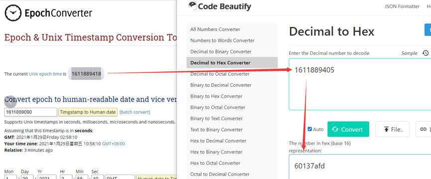
To get the current Unix epoch time, visit the website https://www.epochconverter.com/ :
For example, if the Unix epoch time is 1611889090, you can convert it to hex using a Decimal to Hex Converter available online, such as Code Beautify. For this example, the equivalent hex value is 0x60137afd.
2.6.2 Set Device Time
There are two ways to set the device's time:
1. Through LoRaWAN MAC Command (Default settings)
You need to set AT+SYNCMOD=1 to enable time synchronisation via the MAC command.
Once the PB05-L joins a LoRaWAN network, it sends a MAC command (DeviceTimeReq). The server responds with a DeviceTimeAns to provide the current time to the PB05-L. If the PB05-L fails to get the time from the server, it will use its internal clock and wait for the next time request.
You can use AT+SYNCTDC to set the time request period (default is 10 days).
2. Manually Set Time
You need to set AT+SYNCMOD=0 to enable manual time configuration. Otherwise, the time you set will be overwritten by the time provided by the server.
2.6.3 Poll sensor value
You can poll sensor values based on timestamps from the server.
Below is the downlink command.
| 1byte | 4bytes | 4bytes | 1byte |
| 31 | Timestamp start | Timestamp end | Uplink Interval |
Timestamp start and Timestamp end use Unix Timestamp format as mentioned above. Devices will reply with all data logs during this time period, using the uplink interval.
For example, downlink command ![]()
Is to check 2024/10/31 01:30:00 to 2020/12/1 04:00:00's data
Uplink Internal =5s, means PB05-L will send one packet every 5s, range 5~255s.
2.6.4 Datalog Uplink payload
See, Uplink FPort=3, Datalog sensor value
2.7 Buttons
- ACT button
Long-press the ACT button to reset the device and allow it to join the network again.

- Alarm buttons
When you press the alarm button, the PB05-L immediately uplinks data. The alarm flag is set to 'TRUE,' and the corresponding button status is 'Yes'.

2.8 LED Indicators
The PB05-L has a tri-color LED for easily indicating different stages.
Hold the ACT button until the green light turns on to reset the device. The green LED will flash as the node restarts, the blue LED will flash once when requesting network access, and the green LED will remain on for 5 seconds after successful network access.
In a normal working state:
- When the node restarts, hold the ACT button until the GREEN LED lights up. The GREEN LED will flash as the node restarts.
- The BLUE LED will flash once upon requesting network access.
- The GREEN LED will remain on for 5 seconds after successful network access.
During OTAA Join:
- For each Join Request uplink, the GREEN LED will blink once.
- Once the Join is successful, the GREEN LED will remain on for 5 seconds.
- After joining, for each uplink, either the BLUE or GREEN LED will blink once.
Alarm Button Press:
- When an alarm button is pressed, the RED LED will flash until the node receives an ACK from the platform.
- Once the ACK is received, the BLUE LED will stay on for 5 seconds.
2.9 Buzzer
The PB05 has a button sound and an ACK sound, both of which users can turn on or off using AT+SOUND.
- Button sound is the tone played by the node after an alarm button is pressed.
You can use AT+OPTION to set different button sounds. - ACK sound is the notification tone played when the node receives an ACK.
2.10 E2 Extension Cable


1m Long Breakout Cable for PB05-L
Features:
- Used for AT commands; compatible with LHT52, LHT65N, and PB05-L.
- Supports firmware updates for PB05-L; also works with LHT52 and LHT65N.
- Exposes all pins from the PB05-L Type-C connector.
The following diagram shows the pin mapping between PB05 and the E2 Cable.

3. Configure PB05-L via AT command or LoRaWAN downlink
You can configure PB05-L via AT Command or LoRaWAN Downlink command.
- AT Command Connection:

On a PC, you need to set the serial tool (such as PuTTY or SecureCRT) to a baud rate of 9600 to access the serial console for the PB05-L.
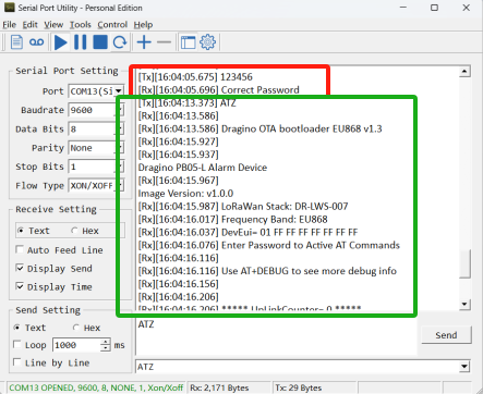
AT commands are disabled by default and require entering a password (default: 123456) to activate them. The AT command input timeout is 5 minutes; after this period, the user must enter the password again.
Enter the password and ATZ to activate the PB05-L, as shown below:
- LoRaWAN Downlink instructions for different platforms can be found here: IoT LoRaWAN Server
There are two types of commands to configure the PB05-L:
General Commands
These commands configure:
- General system settings, such as the uplink interval.
- LoRaWAN protocol and radio-related settings.
These commands are the same for all Dragino devices that support the DLWS-005 LoRaWAN stack (Note**). They can be found on the wiki: End Device Downlink Command.
Commands Specifically Designed for PB05-L
These commands are only valid for the PB05-L, as listed below:
3.1 Downlink Command Set
| Command Example | Function | Response | Downlink |
|---|---|---|---|
| AT+TDC=? | View current TDC time | 1200000 | Default 1200000(ms) |
| AT+TDC=300000 | Set TDC time | OK | 0X0100012C: 300(seconds)
|
| ATZ | Reset node | 0x04FF | |
| AT+FDR | Restore factory settings | 0X04FE | |
| AT+CFM=? | View the current confirmation mode status | 0,7,0 | Default 0,7,0 |
| AT+CFM=1,7,1 | Confirmed uplink mode. The maximum number of retries is seven, and the uplink FCnt increases by 1 for each retry. | OK | 05010701 |
| AT+NJM=? | Check the current network connection method. | 1 | Default 1 |
| AT+NJM=0 | Change the network connection method to ABP. | Attention: Take effect after ATZ | 0X2000: ABP |
| AT+RPL=? | View current RPL settings | 0 | Default 0 |
| AT+RPL=1 | set RPL=1 | OK | 0x2101: |
| AT+ADR=? | View current ADR status | 1 | Default 0 |
| AT+ADR=0 | Set the ADR state to off | OK | 0x2200: Close |
| AT+DR=? | View the current DR settings | OK | |
| AT+DR=1 | Set DR to 1 | OK | 0X22000101: |
| AT+TXP=? | View the current TXP | OK | |
| AT+TXP=1 | Set TXP to 1 | OK | 0X22000101: |
| AT+RJTDC=10 | Set the RJTDC time interval | OK | 0X26000A: |
____________________________ Retrieve stored data for a specified period of time
| 0X3161DE7C7061DE8A800A: | ||
| AT+DDETECT=? | View the current DDETECT setting status and time | 1,1440,2880 | Default 1,1440,2880(min) |
| AT+DDETECT= 1,1440,2880 | Set the DDETECT setting status and time | OK | 0X320005A0: Close |
3.2 Set Password
Feature: Set the device password—maximum 9 digits.
AT Command: AT+PWORD
| Command Example | Function | Response |
| AT+PWORD=? | Show password | 123456 |
| AT+PWORD=999999 | Set password | OK |
Downlink Command:
No downlink command is available for this feature.
3.3 Set button sound and ACK sound
Feature: Turn on/off the button sound and the ACK sound/alarm.
AT Command: AT+SOUND
| Command Example | Function | Response |
AT+SOUND=? | Get the current status of the button sound and the ACK sound | 1,1 |
AT+SOUND=0,1 | Turn off the button sound and turn on the ACK sound | OK |
Downlink Command: 0xA1
Format: Command Code/prefix (0xA1) followed by 2 bytes mode value.
The first byte after 0XA1 sets the button sound, and the second byte after 0XA1 sets the ACK sound. (0: OFF, 1: ON)
- Example: Downlink Payload: A10001 // Set AT+SOUND=0,1 Turn off the button sound and turn on ACK sound.
3.4 Set buzzer music type(0~4)
Feature: Set different alarm key response sounds. There are five different types of button music.
AT Command: AT+OPTION
| Command Example | Function | Response |
AT+OPTION=? | Get the buzzer music type | 3 OK |
| AT+OPTION=1 | Set the buzzer music to type 1 | OK |
Downlink Command: 0xA3
Format: Command Code/Prefix (0xA3) followed by 1 byte mode value.
- Example: Downlink Payload: A300 // Set AT+OPTION=0 to set the buzzer music to type 0.
3.5 Set Valid Push Time
Feature: Set the holding time for pressing the alarm button to avoid miscontact. Values range from 0 ~1000ms.
AT Command: AT+STIME
| Command Example | Function | Response |
AT+STIME=? | Get the button sound time | 0 |
AT+STIME=1000 | Set the button sound time to 1000ms | OK |
Downlink Command: 0xA2
Format: Command Code/Prefix (0xA2) followed by 2 bytes mode value.
- Example: Downlink Payload: A203E8 // Set AT+STIME=1000
Explain: Hold the alarm button for 10 seconds before the node will send the alarm packet.
4. Battery & How to replace
4.1 Battery Type and Replacement
PB05-L uses 2 x AA LR6(1.5v) batteries. If the batteries are running low (Shows 2.1v in the platform). You can buy generic AA batteries and replace them.
Note:
1. The PB05-L doesn't have any screws so you can use a nail to open it by the middle.

2. Make sure the direction is correct when installing the AA batteries.
4.2 Power Consumption Analysis
All Dragino's battery-powered products run in low-power mode. We have an updated battery calculator which based on the measurement of the real device. You can use this calculator to check the battery life and calculate the battery life if you want to use a different transmit interval.
Instructions to use are as below:
Step 1: Download the up-to-date DRAGINO_Battery_Life_Prediction_Table.xlsx from the below link:
Step 2: Open it and choose
- Product Model
- Uplink Interval
- Working Mode
And the Life expectancy in different cases will be shown on the right.

5. OTA Firmware update
You can update the firmware of PB05-L to:
- Change the Frequency band/ region.
- Update with new features.
- Fix bugs.
Firmware and changelog can be downloaded from: Firmware download link
Methods to Update Firmware:
- (Recommended way) OTA firmware update via wireless: http://wiki.dragino.com/xwiki/bin/view/Main/Firmware%20OTA%20Update%20for%20Sensors/
- Update through UART TTL interface: Instruction.
6. Use Cases
6.1 Public Transport Satisfaction
Public transport satisfaction terminals, placed inside buses, trams, or train stations, allow passengers to quickly rate aspects like cleanliness, punctuality, or overall experience after a ride, providing cities and transport operators with valuable real-time feedback, even from locations with poor cellular or WiFi coverage. This helps to improve service quality and passenger satisfaction.

6.2 Event or Conference Feedback
Event or conference feedback terminals, strategically placed at session exits, information booths, or entrance gates, enable attendees to rate specific talks, exhibitors, or their overall event experience on the spot. This setup provides organisers with detailed, location-specific feedback in real time, without relying on constant internet connectivity, allowing them to assess and improve various aspects of the event efficiently.

6.3 Retail Stores or Service Desks
Placed at cashier counters or near store exits, these devices allow customers to quickly rate staff behaviour, checkout experience, and store cleanliness. The feedback is captured in real time, giving store managers valuable, honest insights to help improve service quality and enhance the overall shopping experience.

7. FAQ
7.1 How to design a customised sticker?
PB05-L is shipped with a default PVC stick with satisfied icons. This sticker is not attached to the design for easy customisation purposes. You can design a customised PVC sticker and change the panel design.
Follow this link for the design template.
8. Order Info
Part Number: PB05-L-XX
XX : The default frequency band
- AS923: LoRaWAN AS923 band
- AU915: LoRaWAN AU915 band
- EU433: LoRaWAN EU433 band
- EU868: LoRaWAN EU868 band
- KR920: LoRaWAN KR920 band
- US915: LoRaWAN US915 band
- IN865: LoRaWAN IN865 band
- CN470: LoRaWAN CN470 band
9. Packing Info
Package Includes:
- PB05-L LoRaWAN Push Buttons x 1
Dimension and weight:
- Device Size: cm
- Device Weight: g
- Package Size / pcs: cm
- Weight / pcs: g
10. Support
- Support is provided Monday to Friday, from 09:00 to 18:00 GMT+8. Due to different time zones, we cannot offer live support. However, your questions will be answered as soon as possible in the aforementioned schedule.
- Provide as much information as possible regarding your enquiry (product models, accurately describe your problem and steps to replicate it, etc.) and send an email to support@dragino.com.