LPT01 -- LoRaWAN Handheld Food Thermometer User Manual

Table of Contents:
- 1. Introduction
- 3. Configure LPT01 via AT Command or LoRaWAN Downlink
- 4. Battery & Power Consumption
- 5. OTA Firmware update
- 6. FAQ
- 7. Trouble Shooting
- 8. Order Info
- 9. Packing Info
- 10. Support
1. Introduction
1.1 What is LPT01 LoRaWAN Handheld Food Thermometer
Handheld temperature probes are vital tools for food safety, disease prevention, and regulatory compliance. They help ensure food stays out of the danger zone and that harmful pathogens are effectively eliminated.
The LPT01 is a LoRaWAN-enabled food temperature probe designed for remote monitoring of food temperature. It automatically records temperature data and uploads it to an IoT platform, helping meet food safety regulations while reducing manual documentation errors and saving time.
With real-time alerts for temperature deviations, the LPT01 enhances food safety by allowing swift corrective actions to prevent potential hazards. Its long-range LoRaWAN connectivity ensures reliable data transmission and simplifies deployment and maintenance—dramatically lowering operational costs for food safety management.
1.2 Features
- LoRaWAN v1.0.3 Class A protocol
- LCD display
- Uplink on periodically or alarm event
- PT100 Temperature Sensor
- CR123A 1500mAh Battery
1.3 Specification
Common DC Characteristics:
- Supply Voltage: Built-in Battery , 2.5v ~ 3.0v
- Operating Temperature: -40 ~ 85°C
Probe Spec:
- LPT01 total length: 28cm
- Probe length: 13.5cm
- Probe diameter: 4mm
- External A-grade PT100 temperature sensor
- Class A PT100 collects temperature accuracy ±(0.15 + 0.002 * |t|)°C
- Resolution: 0.01 °C
- Operating Range: -50 °C to 260 °C
LoRa Spec:
- Frequency Range, Band 1 (HF): 862 ~ 1020 Mhz
- Max +22 dBm constant RF output vs.
- RX sensitivity: down to -139 dBm.
- Excellent blocking immunity
Battery:
- CR123A non-rechargeable battery
- Capacity: 1500mAh
- Self-Discharge: <1% / Year @ 25°C
- Max continuously current: 130mA
- Max boost current: 2A, 1 second
Power Consumption
- Sleep Mode: 5uA @ 3.3v
- LoRa Transmit Mode: 125mA @ 20dBm, 82mA @ 14dBm
1.4 Applications
- Logistics and Supply Chain Management
- Food management
- Cold chains solution
- Industrial Monitoring and Control
1.5 Sleep mode and working mode
Deep Sleep Mode: Sensor doesn't have any LoRaWAN activate. This mode is used for storage and shipping to save battery life.
Working Mode: In this mode, Sensor will work as LoRaWAN Sensor to Join LoRaWAN network and send out sensor data to server. Between each sampling/tx/rx periodically, sensor will be in IDLE mode), in IDLE mode, sensor has the same power consumption as Deep Sleep mode.
1.6 Button & LEDs

| Reset Behavior | Function | Response |
|---|---|---|
 Three buttons×5 Three buttons×5 | Reset Device | Reset the device, the signal icon |
| Behavior on STOP | Function | Response |
 >2s >2s | Exits continuous reporting mode | LCD displays "OFF". |
| ×3 | Deactivate Device | Enters deep sleep mode; LCD displays "SLP". |
| Behavior on ℃/℉ | Function | Response |
| >3s | Toggle Units | Switches between °C/°F, converts current value, and saves as default. |
| Behavior on HOLD | Function | Response |
| ×1 | Send one uplink | If sensor is already Joined to LoRaWAN network, sensor will send an uplink packet, LCD screen displays the current temperature once. |
| Toggle Continuous Mode | After entering Continuous mode, "→" icon flashes. |
2.1 How it works?
The LPT01 is configured as LoRaWAN OTAA Class A mode by default. It has OTAA keys to join LoRaWAN network. To connect a local LoRaWAN network, you need to input the OTAA keys in the LoRaWAN IoT server and press the button to activate the LPT01. It will automatically join the network via OTAA and start to send the sensor value. The default uplink interval is 20 minutes.
On each uplink, LPT01 will get the temperature from the sensor and send out to server.
2.2 Quick guide to connect to LoRaWAN server (OTAA)
Following is an example for how to join the TTN v3 LoRaWAN Network. Below is the network structure; we use the LPS8v2 as a LoRaWAN gateway in this example.
The LPS8V2 is already set to connected to TTN network , so what we need to now is configure the TTN server.

Step 1: Create a device in TTN with the OTAA keys from LPT01.
Each LPT01 is shipped with a sticker with the default device EUI as below:
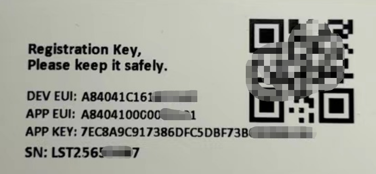
You can enter this key in the LoRaWAN Server portal. Below is TTN screen shot:
Create the application.


Add devices to the created Application.


Enter end device specifics manually.

Add DevEUI and AppKey.
Customize a platform ID for the device.

Step 2: Add decoder
In TTN, user can add a custom payload so it shows friendly reading.
Click this link to get the decoder: https://github.com/dragino/dragino-end-node-decoder/tree/main/
Below is TTN screen shot:


Step 3: Activate on LPT01
Press the button for 5 seconds to activate the LPT01.
Green led will fast blink 5 times, device will enter OTA mode for 3 seconds. And then start to JOIN LoRaWAN network. Green led will solidly turn on for 5 seconds after joined in network.
After join success, it will start to upload messages to TTN and you can see the messages in the panel.

2.3 Working Mode & Uplink Payload
2.3.1 Device Status, FPORT=5
Users can send a downlink command (0x26 01) to request the LP01 device to report its configuration details.
Upon receiving this command, the LP01 will respond by uplinking a payload through FPort 5, formatted as follows:
| Device Status (FPORT=5) | |||||
| Size (bytes) | 1 | 2 | 1 | 1 | 2 |
| Value | Sensor Model | Firmware Version | Frequency Band | Sub-band | BAT |
Example in TTN:

Sensor Model: For LPT01, this value is 0x35
Firmware Version: 0x0100, Means: v1.0.0 version
Frequency Band:
0x01: EU868
0x02: US915
0x03: IN865
0x04: AU915
0x05: KZ865
0x06: RU864
0x07: AS923
0x08: AS923-1
0x09: AS923-2
0x0a: AS923-3
0x0b: CN470
0x0c: EU433
0x0d: KR920
0x0e: MA869
Sub-Band:
AU915 and US915:value 0x00 ~ 0x08
CN470: value 0x0B ~ 0x0C
Other Bands: Always 0x00
Battery Info:
Check the battery voltage.
Ex1: 0x0BE3 = 3043mV
Ex2: 0x0B49 = 2889mV
2.3.2 General acquisition mode, FPORT=2
Behavior:
1. Periodic Uplink: Device transmits sensor data at fixed intervals configured by AT+TDC(default: 20 minutes).
- Trigger Condition: Only time-based (no external triggers).
- Downlink Capability: After the uplink transmission, the device opens a receive window (RX) to allow for potential downlink communication from the server.
2. Manual Uplink (Single HOLD Button Press): If the device is already joined to the LoRaWAN network, pressing the HOLD button once triggers an immediate uplink transmission. The LCD screen displays the current temperature once upon button press.
- Trigger Condition: Single press of the HOLD button (if the device is joined to LoRaWAN).
- No Downlink Capability(purely unidirectional): This uplink transmission does not include a receive window (RX), meaning the device cannot receive downlink messages from the server.
Uplink Payload Format:
Size(bytes) | 2 | 4 | 1 | 2 |
|---|---|---|---|---|
| Value | BAT | Unix TimeStamp | Unit& sampling _times | Temp(PT100)
|
Example in TTN:

Battery
Sensor Battery Level.
Ex1: 0x0B45 = 2885mV
Ex2: 0x0B49 = 2889mV
Unix TimeStamp
Unit TimeStamp Example: 67CF92A7(H) = 1741656743(D)
Put the decimal value into this link(https://www.epochconverter.com))to get the time.
Unit&sampling _times
Example(Unit):
If payload is: 0x04H: ((04 >>7 & 0x01)? "℉":"℃") = 0 , So the unit is °C.
If payload is: 0x86H: ((86 >>7 & 0x01)? "℉":"℃") = 1 , So the unit is ℉.
Example(sampling_times):
If payload is: 0x04H: (0x04 & 0x7F) = 4, So the sampling times is 4.
The sampling times are consistent with the number of collection groups set by the AT+WMOD command.
temperature(PT100)
Example:
- Positive: If payload is 09DDH, (09DD & 8000 == 0), temp = 09DDH /100 = 25.25
- Negative: If payload is FF3FH, (FF3F & 8000 == 1) , temp = (FF3FH - 65536)/10 = -19.3
(FF3F & 8000:Judge whether the highest bit is 1, when the highest bit is 1, it is negative)
- If the value is -327.6, it means the PT100 probe is not connected.
Note: The temperature unit is determined based on the "Unit" of the previous byte.
2.3.3 Continuous Uplink mode, FPORT=2
Overview:
Continuous Uplink Mode enables high-frequency data collection when triggered by specific conditions. This mode overrides the default periodic uplink (TDC) behavior and exits automatically based on configured rules or manual intervention.
Key Behavior:
While in Continuous Mode, TDC timing is paused. The device does not send periodic uplinks at the configured TDC interval (e.g., 20 minutes).
Upon exiting Continuous Mode, the TDC timer resets. The next periodic uplink will occur after the full TDC interval (e.g., 20 minutes) from the moment of exit.
Uplink Payload Format (FPORT=2)
Size (bytes) | 2 | 4 | 1 | Dynamic Lenght , Depend on how many groups |
|---|---|---|---|---|
| Value | BAT | Unix TimeStamp | Unit & sampling | Sensor value, each 2 bytes is a set of sensor values(The maximum is 100 groups).
|
Activation & Deactivation Methods:
1. Entering Continuous Mode
- Manual Activation:
Press and hold HOLD button for >3 seconds to toggle Continuous Mode.
Visual indicator: "→" icon flashes on LCD.
LCD displays real-time temperature updates (press again to pause/resume).
- Downlink Command Activation:
Send downlink payload 0xA5 01 to force entry.
Note: The downlink command can only be received and executed by the device after it initiates an automatic uplink at the scheduled TDC interval or .
- Automatic Trigger (Temperature-Based):
If detected temperature exceeds the upper limit (parameter e in AT+WMOD), the device enters Continuous Mode.
2. Exiting Continuous Mode
The device exits Continuous Mode under any of the following conditions:
- Automatic Exit Conditions
Duration Expired: After running for the configured duration (parameter c in AT+WMOD) (unit: minutes).
Temperature Threshold: If temperature falls below the lower limit (parameter d in AT+WMOD).
- Manual Exit Methods:
Press STOP button for ≥2s → Exits continuous mode, LCD displays "OFF".
Press STOP button 3 times quickly → Deactivates device (deep sleep), LCD displays "SLP".
- Downlink Command Exit:
Send downlink payload 0xA4 01 to force exit.
In Continuous Sampling Mode, LPT01 will record the current sensor data at a fix interval, and report multiply group of data together to server later.
Configuration AT+WMOD=1,a,b,c,d,e
Default Configuration: AT+WMOD=1,10,6,10,0,0
Parameter Definitions:
- a : Sampling interval (seconds), range: 0~255.
- b : Number of readings per uplink (groups), max: 100.
- c : Continuous Mode duration (minutes), range: 0~255.
- d : Lower temperature threshold (exit if below).
- e : Upper temperature threshold (enter if above).
Example Configuration:
Command: AT+WMOD=1,5,5,5,0,10
Behavior:
- Activates if temperature > 10°C.
- Samples every 5 seconds, groups 5 readings, and uplinks.
- Runs for 5 minutes or exits if temperature < 0°C.
Therefore, each uplink payload includes:
- Battery (2 bytes)
- + Group1 Sensor Value (2 Bytes): the last 4th reading for Temp
- + Group2 Sensor Value (2 Bytes): the last 3rd reading for Temp
- + Group3 Sensor Value (2 Bytes): the last 2nd reading for Temp
- + Group4 Sensor Value (2 Bytes): the last reading for Temp
- + Group5 Sensor Value (2 Bytes): reading for Temp
So totally 12 bytes payload in this example.
Notice: Continuous sampling mode may result in a longer payload. the LPT01 will automatically select the appropriate DR uplink data. This may shorten the transmission distance.
Example parse in TTNv3:

2.4 Unix Timestamp
LPT01 uses Unix Timestamp format based on

Key Features
- Timestamp is included in uplink payloads (FPORT=2) for data synchronization.
- Compatible with standard epoch converters like https://www.epochconverter.com/
Below is the converter example

Set Device Time
There are two methods to configure the device’s internal clock:
1. Automatic Sync via LoRaWAN MAC Command (Default)
Requirement: Set SYNCMOD=1(enabled by default).
Behavior:
- After joining the network, the device sends a DeviceTimeReq MAC command.
- The server replies with DeviceTimeAns to synchronize time.
- If synchronization fails, the device uses its internal clock and retries after the interval set by AT+SYNCTDC (default: 10 days).
Note: LoRaWAN Server needs to support LoRaWAN v1.0.3(MAC v1.0.3) or higher to support this MAC command feature, Chirpstack,TTN v3 and loriot support but TTN v2 doesn't support. If server doesn't support this command, it will through away uplink packet with this command, so user will lose the packet with time request for TTN v2 if SYNCMOD=1.
2. Manual Time Setting
Requirement: Set SYNCMOD=0 (disables MAC sync).
Methods: Downlink Command format 0x30 Timestamp(hex representation of timestamp) 00
Example: downlink 3068956BCE00 to set current time : 2025-August-8 Friday 03:15:26
3. Configure LPT01 via AT Command or LoRaWAN Downlink
Command configuration method
The LPT01 can be configured exclusively through LoRaWAN downlink commands. While this manual references AT commands for clarity, these are provided solely to help understand the corresponding downlink payload formats - they cannot be executed directly on the device.
LoRaWAN Downlink instruction for different platforms: IoT LoRaWAN Server
Command Types
There are two kinds of commands to configure LPT01, they are:
1. General Commands.
These commands are to configure:
General system settings like: uplink interval.
LoRaWAN protocol & radio related command.
They are same for all Dragino Device which support DLWS-005 LoRaWAN Stack. These commands can be found on the wiki: End Device AT Commands and Downlink Command
2. LPT01-Specific Commands
These specialized commands control features unique to the LPT01.
Please refer to the detailed descriptions of these commands below.
3.1 Set Transmit Interval Time
Feature: Change LoRaWAN End Node Transmit Interval.
AT Command: AT+TDC
| Command Example | Function | Response |
| AT+TDC=? | Show current transmit Interval | 1200000(Default value) |
AT+TDC=600000 | Set Transmit Interval | OK |
Downlink Command: 0x01
Format: Command Code (0x01) followed by 3 bytes time value.
If the downlink payload=0100003C, it means set the END Node's Transmit Interval to 0x00003C=60(S), while type code is 01.
- Example 1: Downlink Payload: 0100001E // Set Transmit Interval (TDC) = 30 seconds
- Example 2: Downlink Payload: 0100003C // Set Transmit Interval (TDC) = 60 seconds
3.2 Set Continuous uplink mode
Feature: Get or set uplink behaviour in continuous uplink mode.
AT Command: AT+WMOD
| Command Example | Parameters | Explanation |
AT+WMOD=1,a,b,c,d,e | 1: Mode 1 | Continuous Uplink Mode |
a: Set Sampling Interval | Range: 1~255 (Unit: Second) | |
| b: Define how many group of data will be uplink together | Range: 1~100 | |
| c: Duration of operation in continuous acquisition mode | Range: 1~255 | |
| d: Set the temperature lower limit value | Ex1: 0 Below the lower limit value will exit the continuous uplink mode. | |
| e: Set the upper temperature limit value | Ex1: 10 Higher than the upper limit value will enter the continuous uplink mode | |
Example: AT+WMOD=1,5,5,5,0,10 When the measured temperature exceeds 10°C, the node will activate continuous measurement mode, which lasts for 5 minutes, with a sampling interval of 5 seconds, collecting data 5 times, and reporting the comprehensive data once. | ||
Downlink Command: 0xA2
- Downlink payload: 0xA2010505050000000A // Same as AT+WMOD=1,5,5,5,0,10
- Downlink payload: 0xA20105050500000000 // Same as AT+WMOD=1,5,5,5,0,0
Note: If you need to enter the continuous uplink mode immediately, you can control it by going downlink.
- Downlink payload: 0xA5 01 // After receiving the downlink, LPT01 will enter the continuous uplink mode, but if it detects that the current sampled temperature is lower than the set minimum threshold, it will automatically exit the continuous uplink mode。
- Downlink payload: 0xA4 01 // After receiving the downlink, LPT01 will directly exit the continuous uplink mode.
3.3 Set time synchronization method
Feature: This command is used to enable automatic time calibration by time zone(Get or Set time synchronization method).
AT Command: AT+SYNCMOD
| Command Example | Function | Response/Parameter |
|---|---|---|
AT+SYNCMOD=? | Get the current time synchronization method | 1,0 (Default) OK |
| AT+SYNCMOD=aa,bb | aa: Enable/disable automatic time zone calibration | 0: Disable automatic time zone calibration. 1: Enable automatic time zone calibration |
| bb: Set the time zone: -12 ~ 12 | Negative number: West Time Zone Positive number: Eastern Time Zone |
Downlink Command: 0x28
Format: Command Code (0x28) followed by 2 bytes.
- Example 1: Downlink Payload: 28 00 00 // Turn off the time zone calibration time.
- Example 2: Downlink Payload: 28 01 FA // Turn on time zone calibration time, UTC-6
- Example 3: Downlink Payload: 28 01 06 // Turn on time zone calibration time, UTC+6
Note: UTC-6: 256+(-6)=250(D)=0xFA(H)
3.4 Set time synchronization interval
Feature: Get or set time synchronization interval in day or hour.
AT Command: AT+SYNCTDC
| Command Example | Function | Response/Parameter |
|---|---|---|
AT+SYNCTDC=? | Gets the current time synchronization interval | 12,1 (Default) OK |
AT+SYNCTDC=aa,bb | aa: Set the interval for automatic synchronization | Range: 0~255 |
| bb: Set the unit of the time synchronization interval | 0: Unit: day 1: Unit: hour |
Downlink Command: 0x29
Format: Command Code (0x29) followed by 3 bytes.
- Example 1: Downlink Payload: 29 0C 00 // Calibrate once every 12 days
- Example 2: Downlink Payload: 29 0C 01 // Calibrate once every 12 hours
3.5 Temperature Unit
Feature: Get or set Temperature Unit.
AT Command: AT+UNIT
Note: In US915 Band, Default unit is ℉, In other bands, default unit is ℃.
| Command Example | Function | Response/Parameter |
|---|---|---|
| AT+UNIT=? | Gets Temperature unit interval | 0 OK |
| AT+UNIT=a | ||
0: ℉. 1: ℃. | 0: Unit: ℉ 1: Unit: ℃ |
Downlink Command: 0xA1
Format: Command Code (0xA1) followed by 1 bytes.
- Example 1: Downlink Payload: A1 00 // Same as AT+UNIT=0
- Example 2: Downlink Payload: A1 01 // Same as AT+UNIT=1
3.6 Button response time
Feature: Get or set the response time for the hold button.
AT Command: AT+HOLDT
Note:By default, if the device is in idle mode, pressing and holding the HOLD button for 50 milliseconds to 2000 milliseconds will cause the device to send the temperature to the server..
| Command Example | Function | Response/Parameter |
|---|---|---|
| AT+HOLDT=? | Gets Temperature unit interval | 50,2000 |
AT+HOLDT=a,b | ||
a: Minimum Threshold | Range: 50~2000 | |
| b: Maximum Threshold | Range: 50~2000 |
Downlink Command: 0xA3
Format: Command Code (0xA3) followed by 4 bytes.
- Example 1: Downlink Payload: A3 00 32 07 D0 // Same as AT+HOLDT=50,2000
- Example 2: Downlink Payload: A3 00 C8 07 D0 // Same as AT+HOLDT=200,2000
4. Battery & Power Consumption
LPT01 uses CR123A battery pack. See below link for detail information about the battery info and how to replace.
Battery Info & Power Consumption Analyze .
5. OTA Firmware update
User can change firmware LPT01 to:
- Change Frequency band/ region.
- Update with new features.
- Fix bugs.
Firmware and changelog can be downloaded from : Firmware download link
Methods to Update Firmware:
- OTA firmware update via wireless : http://wiki.dragino.com/xwiki/bin/view/Main/Firmware%20OTA%20Update%20for%20Sensors/
6. FAQ
7. Trouble Shooting
8. Order Info
Part Number : LPT01-XX
XX: The default frequency band
- AS923 : LoRaWAN AS923 band
- AU915 : LoRaWAN AU915 band
- EU433 : LoRaWAN EU433 band
- EU868 : LoRaWAN EU868 band
- KR920 : LoRaWAN KR920 band
- US915 : LoRaWAN US915 band
- IN865 : LoRaWAN IN865 band
- CN470 : LoRaWAN CN470 band
9. Packing Info
Package Includes:
- LPT01 LoRaWAN Temperature Collector x 1
Dimension and weight:
- Device Size: cm
- Device Weight: g
- Package Size / pcs : cm
- Weight / pcs : g
10. Support
- Support is provided Monday to Friday, from 09:00 to 18:00 GMT+8. Due to different timezones we cannot offer live support. However, your questions will be answered as soon as possible in the before-mentioned schedule.
- Provide as much information as possible regarding your enquiry (product models, accurately describe your problem and steps to replicate it etc) and send a mail to support@dragino.com.