LHT65N -- Manual do sensor de temperatura e umidade LoRaWAN

Table of Contents:
- 1. Introdução
- 2. Conecte LHT65N ao servidor IoT
- 2.1 Como funciona o LHT65N?
- 2. 2 Como ativar o LHT65N?
- 2.3 Exemplo para ingressar na rede LoRaWAN
- 2.4 Carga útil de uplink (Fport=2)
- 2.4.1 Decodificador em TTN V3
- 2.4.2 Informações da bateria BAT
- 2.4.3 Temperatura interna
- 2.4.4 Umidade interna
- 2.4.5 Ext #
- 2.4.6 Valor externo
- 2.4.6.1 Ext=1, Sensor de Temperatura E3
- 2.4.6.2 Ext=9, sensor E3 com Unix Timestamp
- 2.4.6.3 Ext=6, ADC Sensor(use with E2 Cable)
- 2.4.6.4 Ext=2 TMP117 Sensor( Since Firmware v1.3)
- 2.4.6.5 Ext=11 SHT31 Sensor ( Since Firmware v1.4.1)
- 2.4.6.6 Ext=4 Interrupt Mode(Since Firmware v1.3)
- 2.4.6.7 Ext=8 Counting Mode(Since Firmware v1.3)
- 2.4.6.8 Ext=10, E2 sensor (TMP117)with Unix Timestamp(Since firmware V1.3.2)
- 2.5 Show data on Datacake
- 2.6 Datalog Feature
- 2.7 Alarm Mode & Feature "Multi sampling, one uplink"
- 2.8 LED Indicator
- 2.9 installation
- 3. Sensors and Accessories
- 4. Configure LHT65N via AT command or LoRaWAN downlink
- 4.1 Set Transmit Interval Time
- 4.2 Set External Sensor Mode
- 4.3 Enable/Disable uplink Temperature probe ID
- 4.4 Set Password
- 4.5 Quit AT Command
- 4.6 Set to sleep mode
- 4.7 Set system time
- 4.8 Set Time Sync Mode
- 4.9 Set Time Sync Interval
- 4.10 Print data entries base on page.
- 4.11 Print last few data entries.
- 4.12 Clear Flash Record
- 4.13 Auto Send None-ACK messages
- 4.14 Modified WMOD command for external sensor TMP117 or DS18B20 temperature alarm(Since firmware 1.3.0)
- 5. Battery & How to replace
- 6. FAQ
- 6.1 How to use AT Command?
- 6.2 Where to use AT commands and Downlink commands
- 6.3 How to change the uplink interval?
- 6.4 How to use TTL-USB to connect a PC to input AT commands?
- 6.5 How to use TTL-USB to connect PC to upgrade firmware?
- 6.6 Using USB-TYPE-C to connect to the computer using the AT command
- 6.7 How to use USB-TYPE-C to connect PC to upgrade firmware?
- 6.8 Why can't I see the datalog information
- 7. Order Info
- 8. Packing Info
- 9. Reference material
- 10. FCC Warning
1. Introdução
1.1 O que é LHT65N LoRaWAN Temperatura & Umidade Sensor
O sensor de temperatura e umidade Dragino LHT65N é um sensor LoRaWAN de longo alcance. Inclui um sensor de temperatura e umidade embutido e tem um conector de sensor externo para conectar a um sensor de temperatura externo.
O LHT65N permite que os usuários enviem dados e alcancem distâncias extremamente longas. Fornece comunicação de espectro de propagação de ultra-longo alcance e alta imunidade à interferência, minimizando o consumo atual. Ele visa aplicações profissionais de rede de sensores sem fio, como sistemas de irrigação, medição inteligente, cidades inteligentes, automação de edifícios e assim por diante.
LHT65N tem uma bateria embutida de 2400mAh não recarregável que pode ser usada por até 10 anos*.
LHT65N é totalmente compatível com o protocolo LoRaWAN v1.0.3 Classe A, ele pode trabalhar com um gateway LoRaWAN padrão.
O LHT65N suporta a funcionalidade Datalog. Ele registrará os dados quando não houver cobertura de rede e os usuários podem recuperar o valor do sensor mais tarde para garantir que não haja perda para cada leitura do sensor.
* A vida real da bateria depende de quantas vezes enviar dados, consulte o capítulo do analisador da bateria.
1.2 Características
- Protocolo LoRaWAN v1.0.3 Classe A
- Bandas de frequência: CN470/EU433/KR920/US915/EU868/AS923/AU915
- Comandos AT para alterar os parâmetros
- Parâmetros de configuração remota via LoRaWAN Downlink
- Firmware atualizável através da porta do programa
- Built-in 2400mAh bateria para até 10 anos de uso.
- Built-in sensor de temperatura e umidade
- Sensores externos opcionais
- LED de três cores para indicar o estado de funcionamento
- Recurso de registo de dados (máximo de 3328 registos)
1.3 Especificação
Sensor de temperatura incorporado:
- Resolução: 0,01 °C
- Tolerância de precisão: Tipo ± 0,3 °C
- Deriva a longo prazo: < 0,02 °C/ano
- Faixa de operação: -40 ~ 85 °C
Sensor de humidade incorporado:
- Resolução: 0,04%UR
- Tolerância da precisão: Tipo ±3%RH
- Deriva a longo prazo: < 0,02 °C/ano
- Faixa de operação: 0 ~ 96%RH
Sensor de temperatura externo:
- Resolução: 0,0625 °C
- ±0,5°C precisão de -10°C a +85°C
- ±2°C precisão de -55°C a +125°C
- Faixa de operação: -55 °C ~ 125 °C
2. Conecte LHT65N ao servidor IoT
2.1 Como funciona o LHT65N?
O LHT65N é configurado como o modo LoRaWAN OTAA Classe A por padrão. Cada LHT65N é enviado com um conjunto único mundial de chaves OTAA. Para usar o LHT65N em uma rede LoRaWAN, primeiro, precisamos colocar as chaves OTAA no LoRaWAN Network Server e, em seguida, ativar o LHT65N.
Se o LHT65N estiver sob a cobertura desta rede LoRaWAN. LHT65N pode entrar na rede LoRaWAN automaticamente. Depois de ingressar com sucesso, o LHT65N começará a medir a temperatura e umidade do ambiente e começará a transmitir dados do sensor para o servidor LoRaWAN. O período padrão para cada uplink é de 20 minutos.
2. 2 Como ativar o LHT65N?
O LHT65N tem dois modos de trabalho:
Modo de Suspensão Profunda: LHT65N não tem nenhuma ativação LoRaWAN. Este modo é usado para armazenamento e transporte para economizar a vida útil da bateria.
Modo de Trabalho: Neste modo, o LHT65N funciona como o modo Sensor LoRaWAN para entrar na rede LoRaWAN e enviar os dados do sensor para o servidor. Entre cada amostragem/tx/rx periodicamente, LHT65N estará no modo STOP (modo IDLE), no modo STOP, LHT65N tem o mesmo consumo de energia que o modo Deep Sleep.
O LHT65N é definido no modo de sono profundo por padrão; O botão ACT na frente é para alternar para diferentes modos:

| Comportamento no ACT | Função | Acção |
|---|---|---|
| Pressionando ACT entre 1s < tempo < 3s | Teste o estado da ligação ascendente | Se o LHT65N já estiver unido à rede rhe LoRaWAN, o LHT65N enviará um pacote de uplink, se o LHT65N tiver sensor externo conectado, o led azul piscará uma vez. Se o LHT65N não tiver sensor externo, o led vermelho piscará uma vez. |
| Pressionando ACT por mais de 3s | Dispositivo Activo | O led verde piscará rapidamente 5 vezes, o LHT65N entrará no modo de trabalho e começará a juntar-se à rede LoRaWAN. O led verde ligará solidamente por 5 segundos após a junção na rede. |
| Pressione rapidamente ACT 5 vezes. | Desactivar o Dispositivo | O led vermelho ficará sólido durante 5 segundos. Significa que LHT65N está em modo de sono profundo. |
2.3 Exemplo para ingressar na rede LoRaWAN
Esta seção mostra um exemplo de como entrar no servidor IoT TTN V3 LoRaWAN. O uso com outros servidores IoT LoRaWAN é de um procedimento semelhante.

Suponha que o LPS8N já esteja configurado para se conectar à rede TTN V3, então ele fornece cobertura de rede para LHT65N. Em seguida, precisamos adicionar o dispositivo LHT65N em TTN V3:
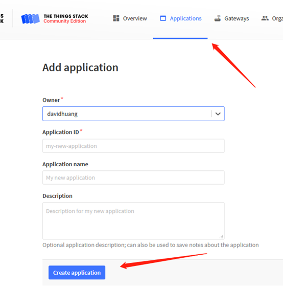
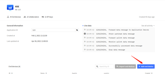
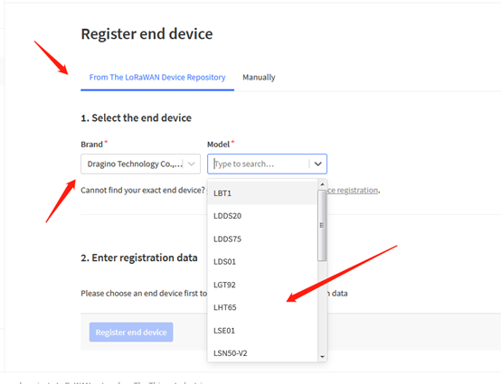
2.3.1 Etapa 1: Crie dispositivo n ttn
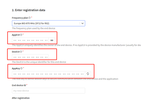
Crie um dispositivo no TTN V3 com as teclas OTAA do LHT65N.
Cada LHT65N é enviado com um adesivo com seu dispositivo eui, chave de aplicativo e aplicativo eui como abaixo:

O usuário pode inserir essas chaves no portal do servidor Lorawan. Abaixo está a captura de tela do TTN V3:
Adicione o aplicativo EUI no aplicativo.
Nota: LHT65N Use a mesma carga útil que LHT65.
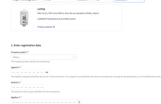
INSIDE APP EUI, APP KEY e DEV EUI:
2.3.2 Passo 2: Ative o LHT65N pressionando o botão ACT por mais de 5 segundos.
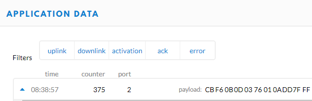
Use o botão ACT para ativar o LHT65N e ele se conectará automaticamente à rede TTN V3. Após o sucesso da junção, ele começará a carregar os dados do sensor para o TTN V3 e o usuário poderá ver no painel.

2.4 Carga útil de uplink (Fport=2)
A carga de uplink inclui totalmente 11 bytes. Os pacotes de uplink usam FPORT=2 e a cada 20 minutos enviam um uplink por padrão.
Após cada uplink, o LED AZUL piscará uma vez.
| Tamanho( bytes) | 2 | 2 | 2 | 1 | 4 |
|---|---|---|---|---|---|
| Valor | Ext # |
- Os primeiros 6 bytes: tem significados fixos para cada LHT65N.
- O 7º byte (EXT #): define o modelo do sensor externo.
- O 8º ~ 11º byte: o valor para o valor do sensor externo. A definição é baseada no tipo de sensor externo. (Se EXT=0, não haverá esses quatro bytes.)
2.4.1 Decodificador em TTN V3
Quando o payload do uplink chega TTNv3, ele mostra o formato HEX e não é fácil de ler. Podemos adicionar LHT65N decodificador em TTNv3 para leitura amigável.
Abaixo está a posição para colocar o decodificador e o decodificador LHT65N pode ser baixado aqui : https://github.com/dragino/dragino-end-node-decoder

2.4.2 Informações da bateria BAT
Esses dois bytes de BAT incluem o estado da bateria e a tensão atual.
Bit(bit) | [15:14] | [13:0] |
|---|---|---|
| Valor | Estado MTD 00 b): Ultra baixo ( MTD <= 2,50v) 01 b): Baixo (2,50v <=MTD <= 2,55v) 10 b): OK (2,55v <= MTD <=2,65v) 11 b): Bom (MTD >= 2,65v) | Na realidade, tensão MTD |
(b) significa binário

Verifique a tensão da bateria para LHT65N.
- Status BAT=(0Xcba4>>14)&0xFF=11 (BIN), muito bom
- Tensão da bateria = 0xCBA4 & 0x3FFF = 0x0BA4 = 2980mV
2.4.3 Temperatura interna

- Temperatura: 0x0ABB/100=27,47ÿ

- Temperatura: (0xF5C6-65536)/100=-26,18ÿ
2.4.4 Umidade interna

- Umidade: 0x025C/10=60,4%
2.4.5 Ext #
Bytes para Sensor Externo:
| EXT # Valor | Tipo de sensor externo |
|---|---|
| 0x01 | Sensor E3, Sensor de Temperatura |
| 0x09 | Sensor E3, Sensor de Temperatura, Mod de Registro de Dados |
2.4.6 Valor externo
2.4.6.1 Ext=1, Sensor de Temperatura E3
- DS18B20 temp=0x0ADD/100=27,81ÿ
Os últimos 2 bytes de dados não têm sentido.

- Temperatura externa= (0xF54F-65536)/100=-27.37℃
F54F: (F54F & 8000 == 1) , temp = (F54F - 65536)/100 = 27,37℃
(0105 & 8000: Julgue se o bit mais alto é 1, quando o bit mais alto é 1, é negativo)
Os últimos 2 bytes de dados não têm sentido
Se o sensor externo for 0x01 e não houver temperatura externa conectada. A temperatura será ajustada para 7FFF que é 327.67℃
2.4.6.2 Ext=9, sensor E3 com Unix Timestamp
O modo Timestamp é projetado para LHT65N com sonda E3, ele enviará a carga útil de uplink com timestamp Unix. Com a limitação de 11 bytes (distância máxima da banda AU915/US915/AS923), o modo de carimbo de hora será falta de campo de tensão BAT, em vez disso, ele mostra o status da bateria. A carga útil é a seguinte:
| Tamanho( bytes) | 2 | 2 | 2 | 1 | 4 |
|---|---|---|---|---|---|
| Valor | Temperatura externa | Estado MTD & Umidade incorporada | Estado & Ext |
- Status da bateria e umidade interna
| Bit(bit) | [15:14] | [11:0] |
|---|---|---|
| Value | BAT Status |
- Status & Ext Byte
| Bits | 7 | 6 | 5 | 4 | [3:0] |
| Status&Ext | None-ACK Flag | Poll Message FLAG | Sync time OK | Unix Time Request | Ext: 0b(1001) |
- Poll Message Flag: 1: This message is a poll message reply, 0: means this is a normal uplink.
- Sync time OK: 1: Set time ok,0: N/A. After time SYNC request is sent, LHT65N will set this bit to 0 until got the time stamp from the application server.
- Unix Time Request: 1: Request server downlink Unix time, 0 : N/A. In this mode, LHT65N will set this bit to 1 every 10 days to request a time SYNC. (AT+SYNCMOD to set this)
2.4.6.3 Ext=6, ADC Sensor(use with E2 Cable)
In this mode, user can connect external ADC sensor to check ADC value. The 3V3_OUT can
be used to power the external ADC sensor; user can control the power on time for this
sensor by setting:
AT+EXT=6,timeout Time to power this sensor, from 0 ~ 65535ms
For example:
AT+EXT=6,1000 will power this sensor for 1000ms before sampling the ADC value.
Or use downlink command A2 to set the same.
The measuring range of the node is only about 0.1V to 1.1V The voltage resolution is about 0.24mv.
When the measured output voltage of the sensor is not within the range of 0.1V and 1.1V, the output voltage terminal of the sensor shall be divided The example in the following figure is to reduce the output voltage of the sensor by three times If it is necessary to reduce more times, calculate according to the formula in the figure and connect the corresponding resistance in series.

When ADC_IN1 pin is connected to GND or suspended, ADC value is 0

When the voltage collected by ADC_IN1 is less than the minimum range, the minimum range will be used as the output; Similarly, when the collected voltage is greater than the maximum range, the maximum range will be used as the output.
1) The minimum range is about 0.1V. Each chip has internal calibration, so this value is close to 0.1V

2) The maximum range is about 1.1V. Each chip has internal calibration, so this value is close to 1.1v

3) Within range

2.4.6.4 Ext=2 TMP117 Sensor(Since Firmware v1.3)
Ext=2,Temperature Sensor(TMP117):

Interrupt Mode and Counting Mode:
The external cable NE2 can be use for MOD4 and MOD8
2.4.6.5 Ext=11 SHT31 Sensor (Since Firmware v1.4.1)
Ext=11,Temperature & Humidity Sensor(SHT31):

2.4.6.6 Ext=4 Interrupt Mode(Since Firmware v1.3)
Note: In this mode, 3.3v output will be always ON. LHT65N will send an uplink when there is a trigger.
Interrupt Mode can be used to connect to external interrupt sensors such as:
Case 1: Door Sensor. 3.3v Out for such sensor is just to detect Open/Close.
In Open State, the power consumption is the same as if there is no probe
In Close state, the power consumption will be 3uA higher than normal.

Ext=4,Interrupt Sensor:
AT+EXT=4,1 | Sent uplink packet in both rising and falling interrupt |
AT+EXT=4,2 | Sent uplink packet only in falling interrupt |
AT+EXT=4,3 | Sent uplink packet only in rising interrupt |
Trigger by falling edge:

Trigger by raising edge:

2.4.6.7 Ext=8 Counting Mode(Since Firmware v1.3)
Note: In this mode, 3.3v output will be always ON. LHT65N will count for every interrupt and uplink periodically.
Case 1: Low power consumption Flow Sensor, such flow sensor has pulse output and the power consumption in uA level and can be powered by LHT65N.

Case 2: Normal Flow Sensor: Such flow sensor has higher power consumption and is not suitable to be powered by LHT65N. It is powered by external power and output <3.3v pulse

Ext=8, Counting Sensor ( 4 bytes):
AT+EXT=8,0 | Count at falling interrupt |
AT+EXT=8,1 | Count at rising interrupt |
AT+SETCNT=60 | Sent current count to 60 |

A2 downlink Command:
A2 02: Same as AT+EXT=2 (AT+EXT= second byte)
A2 06 01 F4: Same as AT+EXT=6,500 (AT+EXT= second byte, third and fourth bytes)
A2 04 02: Same as AT+EXT=4,2 (AT+EXT= second byte, third byte)
A2 08 01 00: Same as AT+EXT=8,0 (AT+EXT= second byte, fourth byte)
A2 08 02 00 00 00 3C: Same as AT+ SETCNT=60 (AT+ SETCNT = 4th byte and 5th byte and 6th byte and 7th byte)
2.4.6.8 Ext=10, E2 sensor (TMP117)with Unix Timestamp(Since firmware V1.3.2)
Timestamp mode is designed for LHT65N with E2 probe, it will send the uplink payload with Unix timestamp. With the limitation of 11 bytes (max distance of AU915/US915/AS923 band), the time stamp mode will be lack of BAT voltage field, instead, it shows the battery status. The payload is as below:
Size(bytes) | 2 | 2 | 2 | 1 | 4 |
|---|---|---|---|---|---|
Value | External temperature | BAT Status & Built-in Humidity | Status & Ext |
- Battery status & Built-in Humidity
| Bit(bit) | [15:14] | [11:0] |
|---|---|---|
| Value | BAT Status |
- Status & Ext Byte
| Bits | 7 | 6 | 5 | 4 | [3:0] |
| Status&Ext | None-ACK Flag | Poll Message FLAG | Sync time OK | Unix Time Request | Ext: 0b(1001) |
- Poll Message Flag: 1: This message is a poll message reply, 0: means this is a normal uplink.
- Sync time OK: 1: Set time ok, 0: N/A. After time SYNC request is sent, LHT65N will set this bit to 0 until got the time stamp from the application server.
- Unix Time Request: 1: Request server downlink Unix time, 0 : N/A. In this mode, LHT65N will set this bit to 1 every 10 days to request a time SYNC. (AT+SYNCMOD to set this)
2.5 Show data on Datacake
Datacake IoT platform provides a human-friendly interface to show the sensor data, once we have sensor data in TTN V3, we can use Datacake to connect to TTN V3 and see the data in Datacake. Below are the steps:
Step 1: Be sure that your device is programmed and properly connected to the LoRaWAN network.
Step 2: Configure your Application to forward data to Datacake you will need to add integration. Go to TTN V3 Console --> Applications --> Integrations --> Add Integrations.
Add Datacake:

Select default key as Access Key:

In Datacake console (https://datacake.co/) , add LHT65 device.


2.6 Datalog Feature
Datalog Feature is to ensure IoT Server can get all sampling data from Sensor even if the LoRaWAN network is down. For each sampling, LHT65N will store the reading for future retrieving purposes. There are two ways for IoT servers to get datalog from LHT65N.
2.6.1 Ways to get datalog via LoRaWAN
There are two methods:
Method 1: IoT Server sends a downlink LoRaWAN command to poll the value for specified time range.
Method 2: Set PNACKMD=1, LHT65N will wait for ACK for every uplink, when there is no LoRaWAN network, LHT65N will mark these records with non-ack messages and store the sensor data, and it will send all messages (10s interval) after the network recovery.
Note for method 2:
- a) LHT65N will do an ACK check for data records sending to make sure every data arrive server.
- b) LHT65N will send data in CONFIRMED Mode when PNACKMD=1, but LHT65N won't re-transmit the packet if it doesn't get ACK, it will just mark it as a NONE-ACK message. In a future uplink if LHT65N gets a ACK, LHT65N will consider there is a network connection and resend all NONE-ACK Message.
Below is the typical case for the auto-update datalog feature (Set PNACKMD=1)

2.6.2 Unix TimeStamp
LHT65N uses Unix TimeStamp format based on

User can get this time from link: https://www.epochconverter.com/ :
Below is the converter example

So, we can use AT+TIMESTAMP=1611889405 or downlink 3060137afd00 to set the current time 2021 – Jan -- 29 Friday 03:03:25
2.6.3 Set Device Time
There are two ways to set device's time:
1. Through LoRaWAN MAC Command (Default settings)
User need to set SYNCMOD=1 to enable sync time via MAC command.
Once LHT65N Joined LoRaWAN network, it will send the MAC command (DeviceTimeReq) and the server will reply with (DeviceTimeAns) to send the current time to LHT65N. If LHT65N fails to get the time from the server, LHT65N will use the internal time and wait for next time request (AT+SYNCTDC to set the time request period, default is 10 days).
Note: LoRaWAN Server need to support LoRaWAN v1.0.3(MAC v1.0.3) or higher to support this MAC command feature, Chirpstack,TTN V3 v3 and loriot support but TTN V3 v2 doesn't support. If server doesn't support this command, it will through away uplink packet with this command, so user will lose the packet with time request for TTN V3 v2 if SYNCMOD=1.
2. Manually Set Time
User needs to set SYNCMOD=0 to manual time, otherwise, the user set time will be overwritten by the time set by the server.
2.6.4 Poll sensor value
User can poll sensor value based on timestamps from the server. Below is the downlink command.
| 1byte | 4bytes | 4bytes | 1byte |
| 31 | Timestamp start | Timestamp end | Uplink Interval |
Timestamp start and Timestamp end use Unix TimeStamp format as mentioned above. Devices will reply with all data log during this time period, use the uplink interval.
For example, downlink command 31 5FC5F350 5FC6 0160 05
Is to check 2020/12/1 07:40:00 to 2020/12/1 08:40:00's data
Uplink Internal =5s, means LHT65N will send one packet every 5s. range 5~255s.
2.6.5 Datalog Uplink payload
The Datalog poll reply uplink will use below payload format.
Retrieval data payload:
Size(bytes) | 2 | 2 | 2 | 1 | 4 |
|---|---|---|---|---|---|
| Value | External sensor data | Built In Temperature | Built-in Humidity | Poll message flag & Ext | Unix Time Stamp |
Poll message flag & Ext:

No ACK Message: 1: This message means this payload is fromn Uplink Message which doesn't get ACK from the server before ( for PNACKMD=1 feature)
Poll Message Flag: 1: This message is a poll message reply.
- Poll Message Flag is set to 1.
- Each data entry is 11 bytes, to save airtime and battery, devices will send max bytes according to the current DR and Frequency bands.
For example, in US915 band, the max payload for different DR is:
a) DR0: max is 11 bytes so one entry of data
b) DR1: max is 53 bytes so devices will upload 4 entries of data (total 44 bytes)
c) DR2: total payload includes 11 entries of data
d) DR3: total payload includes 22 entries of data.
If devise doesn't have any data in the polling time. Device will uplink 11 bytes of 0
Example:
If LHT65N has below data inside Flash:
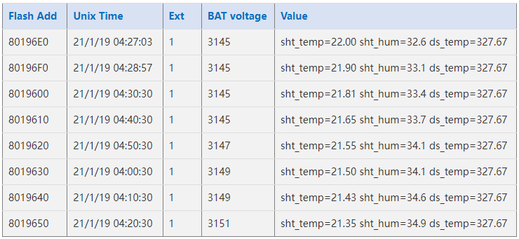
If user sends below downlink command: 3160065F9760066DA705
Where : Start time: 60065F97 = time 21/1/19 04:27:03
Stop time: 60066DA7= time 21/1/19 05:27:03
LHT65N will uplink this payload.

7FFF089801464160065F97 7FFF 088E 014B 41 60066009 7FFF0885014E41600660667FFF0875015141600662BE7FFF086B015541600665167FFF08660155416006676E7FFF085F015A41600669C67FFF0857015D4160066C1E
Where the first 11 bytes is for the first entry:
7FFF089801464160065F97
Ext sensor data=0x7FFF/100=327.67
Temp=0x088E/100=22.00
Hum=0x014B/10=32.6
poll message flag & Ext=0x41,means reply data,Ext=1
Unix time is 0x60066009=1611030423s=21/1/19 04:27:03
2.7 Alarm Mode & Feature "Multi sampling, one uplink"
when the device is in alarm mode, it checks the built-in sensor temperature for a short time. if the temperature exceeds the preconfigured range, it sends an uplink immediately.
Note: alarm mode adds a little power consumption, and we recommend extending the normal read time when this feature is enabled.
2.7.1 ALARM MODE ( Since v1.3.1 firmware)
Internal GXHT30 temperature alarm(Acquisition time: fixed at one minute)
Downlink Command:
AT+WMOD=1: A501 , AT+WMOD=0 : A600
AT+CITEMP=1 : A60001
AT+ARTEMP=1,60 : A70001003C
AT+ARTEMP=-16,60 : A7FFF0003C
AT+LEDALARM=1 : 3601
Downlink Command: AAXXXXXXXXXXXXXX
Total bytes: 8 bytes
Example: AA0100010001003C
WMOD=01
CITEMP=0001
TEMPlow=0001
TEMPhigh=003C
DS18B20 and TMP117 Threshold Alarm
AT+WMOD=1,60,-10,20
Downlink Command:
Example: A5013CFC180014
MOD=01
CITEMP=3C(S)
TEMPlow=FC18
TEMPhigh=0014
Fluctuation alarm for DS18B20 and TMP117(Acquisition time: minimum 1s)
AT+WMOD=2,60,5
Downlink Command:
Example: A5023C05
MOD=02
CITEMP=3C(S)
temperature fluctuation=05
Sampling multiple times and uplink together
AT+WMOD=3,1,60,20,-16,32,1
Explain:
- parameter1: Set Working Mode to Mode 3
- parameter2: Set the temperature sampling mode to 1(1:DS18B20;2:TMP117;3: Internal GXHT30).
- parameter3: Sampling Interval is 60s.
- parameter4: When there is 20 sampling dats, Device will send these data via one uplink. (max value is 60, means max 60 sampling in one uplink)
- parameter5 & parameter6: Temperature alarm range is -16 to 32°C,
- parameter7: 1 to enable temperature alarm, 0 to disable the temperature alarm. If alarm is enabled, a data will be sent immediately if temperate exceeds the Alarm range.
Downlink Command:
Example: A50301003C14FFF0002001
MOD=03
TEMP=DS18B20
CITEMP=003C(S)
Total number of acquisitions=14
TEMPlow=FFF0
TEMPhigh=0020
ARTEMP=01
Uplink payload( Fport=3)
Example: CBEA0109920A4109C4
BatV=CBEA
TEMP=DS18B20
Temp1=0992 // 24.50℃
Temp2=0A41 // 26.25℃
Temp3=09C4 // 25.00℃
Note: This uplink will automatically select the appropriate DR according to the data length
In this mode, the temperature resolution of ds18b20 is 0.25℃ to save power consumption
2.7.2 ALARM MODE ( Before v1.3.1 firmware)
Downlink Command: AAXXXXXXXXXXXXXX
Total bytes: 8 bytes
Example:AA0100010001003C
WMOD=01
CITEMP=0001
TEMPlow=0001
TEMPhigh=003C
2.8 LED Indicator
The LHT65 has a triple color LED which for easy showing different stage .
While user press ACT button, the LED will work as per LED status with ACT button.
In a normal working state:
- For each uplink, the BLUE LED or RED LED will blink once.
BLUE LED when external sensor is connected. - RED LED when external sensor is not connected
- For each success downlink, the PURPLE LED will blink once
2.9 installation

3. Sensors and Accessories
3.1 E2 Extension Cable


1m long breakout cable for LHT65N. Features:
Use for AT Command, works for both LHT52/LHT65N
Update firmware for LHT65N, works for both LHT52/LHT65N
Supports ADC mode to monitor external ADC
Supports Interrupt mode
Exposed All pins from the LHT65N Type-C connector.

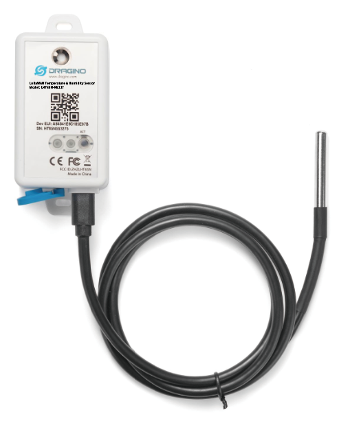
3.2 E3 Temperature Probe


Temperature sensor with 2 meters cable long
- Resolution: 0.0625 °C
- ±0.5°C accuracy from -10°C to +85°C
- ±2°C accuracy from -55°C to +125°C
- Operating Range: -40 ~ 125 °C
- Working voltage 2.35v ~ 5v
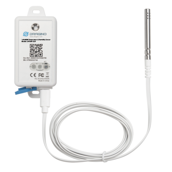
3.3 E31F Temperature Probe


Temperature sensor with 1 meters cable long
Built-in Temperature Sensor:
- Resolution: 0.01 °C
- Accuracy Tolerance : Typ ±0.3 °C
- Long Term Drift: < 0.02 °C/yr
- Operating Range: -40 ~ 80 °C
Built-in Humidity Sensor:
- Resolution: 0.04 % RH
- Accuracy Tolerance : Typ ±3 % RH
- Long Term Drift: < 0.02 °C/yr
- Operating Range: 0 ~ 96 % RH
External Temperature Sensor :
- Resolution: 0.01 °C
- Accuracy Tolerance : Typical ±0.3 °C
- Long Term Drift: < 0.02 °C/yr
- Operating Range: -40 ~ 125 °C
External Humidity Sensor :
- Resolution: 0.04 % RH
- Accuracy Tolerance : Typ ±3 % RH
- Long Term Drift: < 0.02 °C/yr
- Operating Range: 0 ~ 96 % RH
4. Configure LHT65N via AT command or LoRaWAN downlink
Use can configure LHT65N via AT Command or LoRaWAN Downlink.
AT Command Connection: See FAQ.
LoRaWAN Downlink instruction for different platforms: IoT LoRaWAN Server
There are two kinds of commands to configure LHT65N, they are:
General Commands.
These commands are to configure:
General system settings like: uplink interval.
LoRaWAN protocol & radio-related commands.
They are the same for all Dragino Devices which supports DLWS-005 LoRaWAN Stack(Note**). These commands can be found on the wiki: End Device Downlink Command
Commands special design for LHT65N
These commands are only valid for LHT65N, as below:
4.1 Set Transmit Interval Time
Feature: Change LoRaWAN End Node Transmit Interval.
AT Command: AT+TDC
| Command Example | Function | Response |
| AT+TDC=? | Show current transmit Interval | 30000 OK the interval is 30000ms = 30s |
| AT+TDC=60000 | Set Transmit Interval | OK Set transmit interval to 60000ms = 60 seconds |
Downlink Command: 0x01
Format: Command Code (0x01) followed by 3 bytes time value.
If the downlink payload=0100003C, it means set the END Node's Transmit Interval to 0x00003C=60(S), while type code is 01.
- Example 1: Downlink Payload: 0100001E // Set Transmit Interval (TDC) = 30 seconds
- Example 2: Downlink Payload: 0100003C // Set Transmit Interval (TDC) = 60 seconds
4.2 Set External Sensor Mode
Feature: Change External Sensor Mode.
AT Command: AT+EXT
| Command Example | Function | Response |
| AT+EXT=? | Get current external sensor mode | 1 OK External Sensor mode =1 |
| AT+EXT=1 | Set external sensor mode to 1 | |
| AT+EXT=9 | Set to external DS18B20 with timestamp | |
Downlink Command: 0xA2
Total bytes: 2 ~ 5 bytes
Example:
- 0xA201: Set external sensor type to E1
- 0xA209: Same as AT+EXT=9
- 0xA20702003c: Same as AT+SETCNT=60
4.3 Enable/Disable uplink Temperature probe ID
Feature: If PID is enabled, device will send the temperature probe ID on:
First Packet after OTAA Join
Every 24 hours since the first packet.
PID is default set to disable (0)
AT Command:
| Command Example | Function | Response |
| AT+PID=1 | Enable PID uplink | OK |
Downlink Command:
- 0xA800 --> AT+PID=0
- 0xA801 --> AT+PID=1
4.4 Set Password
Feature: Set device password, max 9 digits
AT Command: AT+PWORD
| Command Example | Function | Response |
| AT+PWORD=? | Show password | 123456 OK |
| AT+PWORD=999999 | Set password | OK |
Downlink Command:
No downlink command for this feature.
4.5 Quit AT Command
Feature: Quit AT Command mode, so user needs to input password again before use AT Commands.
AT Command: AT+DISAT
| Command Example | Function | Response |
| AT+DISAT | Quit AT Commands mode | OK |
Downlink Command:
No downlink command for this feature.
4.6 Set to sleep mode
Feature: Set device to sleep mode
- AT+Sleep=0 : Normal working mode, device will sleep and use lower power when there is no LoRa message
- AT+Sleep=1 : Device is in deep sleep mode, no LoRa activation happen, used for storage or shipping.
AT Command: AT+SLEEP
| Command Example | Function | Response |
| AT+SLEEP | Set to sleep mode | Clear all stored sensor data… OK |
Downlink Command:
- There is no downlink command to set to Sleep mode.
4.7 Set system time
Feature: Set system time, unix format. See here for format detail.
AT Command:
| Command Example | Function |
| AT+TIMESTAMP=1611104352 | OK Set System time to 2021-01-20 00:59:12 |
Downlink Command:
0x306007806000 // Set timestamp to 0x(6007806000),Same as AT+TIMESTAMP=1611104352
4.8 Set Time Sync Mode
Feature: Enable/Disable Sync system time via LoRaWAN MAC Command (DeviceTimeReq), LoRaWAN server must support v1.0.3 protocol to reply this command.
SYNCMOD is set to 1 by default. If user want to set a different time from LoRaWAN server, user need to set this to 0.
AT Command:
| Command Example | Function |
| AT+SYNCMOD=1 | Enable Sync system time via LoRaWAN MAC Command (DeviceTimeReq) |
Downlink Command:
0x28 01 // Same As AT+SYNCMOD=1
0x28 00 // Same As AT+SYNCMOD=0
4.9 Set Time Sync Interval
Feature: Define System time sync interval. SYNCTDC default value: 10 days.
AT Command:
| Command Example | Function |
| AT+SYNCTDC=0x0A | Set SYNCTDC to 10 (0x0A), so the sync time is 10 days. |
Downlink Command:
0x29 0A // Same as AT+SYNCTDC=0x0A
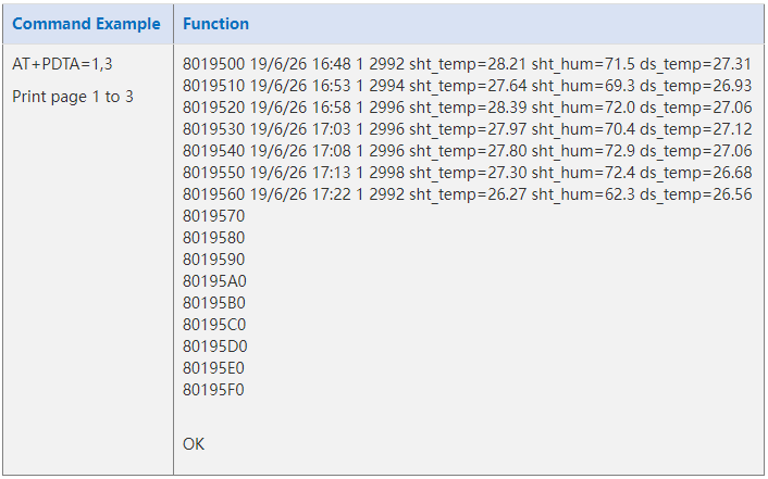
4.10 Print data entries base on page.
Feature: Print the sector data from start page to stop page (max is 416 pages).
AT Command: AT+PDTA
Downlink Command:
No downlink commands for feature
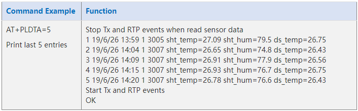
4.11 Print last few data entries.
Feature: Print the last few data entries
AT Command: AT+PLDTA
Downlink Command:
No downlink commands for feature
4.12 Clear Flash Record
Feature: Clear flash storage for data log feature.
AT Command: AT+CLRDTA
| Command Example | Function | Response |
| AT+CLRDTA | Clear date record | Clear all stored sensor data… OK |
Downlink Command: 0xA3
- Example: 0xA301 // Same as AT+CLRDTA
4.13 Auto Send None-ACK messages
Feature: LHT65N will wait for ACK for each uplink, If LHT65N doesn't get ACK from the IoT server, it will consider the message doesn't arrive server and store it. LHT65N keeps sending messages in normal periodically. Once LHT65N gets ACK from a server, it will consider the network is ok and start to send the not-arrive message.
AT Command: AT+PNACKMD
The default factory setting is 0
| Command Example | Function | Response |
|---|---|---|
| AT+PNACKMD=1 | Poll None-ACK message | OK |
Downlink Command: 0x34
- Example: 0x3401 // Same as AT+PNACKMD=1
4.14 Modified WMOD command for external sensor TMP117 or DS18B20 temperature alarm(Since firmware 1.3.0)
Feature: Set internal and external temperature sensor alarms.
| Command Example | Function | Response |
|---|---|---|
| AT+WMOD=parameter1,parameter2,parameter3,parameter4 | Set internal and external temperature sensor alarms | OK |
AT+WMOD=parameter1,parameter2,parameter3,parameter4
Parameter 1: Alarm mode:
0): Cancel
1): Threshold alarm
2): Fluctuation alarm
Parameter 2: Sampling time. Unit: seconds, up to 255 seconds.
Note: When the collection time is less than 60 seconds and always exceeds the set alarm threshold, the sending interval will not be the collection time, but will be sent every 60 seconds.
Parameter 3 and parameter 4:
1): If Alarm Mode is set to 1: Parameter 3 and parameter 4 are valid, as before, they represent low temperature and high temperature.
Such as AT+WMOD=1,60,45,105, it means high and low temperature alarm.
2): If Alarm Mode is set to 2: Parameter 3 is valid, which represents the difference between the currently collected temperature and the last uploaded temperature.
Such as AT+WMOD=2,10,2,it means that it is a fluctuation alarm.
If the difference between the current collected temperature and the last Uplin is ±2 degrees, the alarm will be issued.
Downlink Command: 0xA5
0xA5 00 -- AT+WMOD=0.
0xA5 01 0A 11 94 29 04 -- AT+WMOD=1,10,45,105 (AT+WMOD = second byte, third byte, fourth and fifth bytes divided by 100, sixth and seventh bytes divided by 100 )
0XA5 01 0A F9 C0 29 04 --AT+WMOD=1,10,-16,105(Need to convert -16 to -1600 for calculation,-1600(DEC)=FFFFFFFFFFFFF9C0(HEX) FFFFFFFFFFFFF9C0(HEX) +10000(HEX)=F9C0(HEX))
0xA5 02 0A 02 -- AT+WMOD=2,10,2 (AT+WMOD = second byte, third byte, fourth byte)
0xA5 FF -- After the device receives it, upload the current alarm configuration (FPORT=8). Such as 01 0A 11 94 29 04 or 02 0A 02.
5. Battery & How to replace
5.1 Battery Type
LHT65N is equipped with a 2400mAH Li-MnO2 (CR17505) battery . The battery is an un-rechargeable battery with low discharge rate targeting for up to 8~10 years use. This type of battery is commonly used in IoT devices for long-term running, such as water meters.
The discharge curve is not linear so can't simply use percentage to show the battery level. Below is the battery performance.

The minimum Working Voltage for the LHT65N is ~ 2.5v. When battery is lower than 2.6v, it is time to change the battery.
5.2 Replace Battery
LHT65N has two screws on the back, Unscrew them, and changing the battery inside is ok. The battery is a general CR17450 battery. Any brand should be ok.


5.3 Battery Life Analyze
Dragino battery-powered products are all run in Low Power mode. User can check the guideline from this link to calculate the estimated battery life:
https://www.dragino.com/downloads/downloads/LoRa_End_Node/Battery_Analyze/DRAGINO_Battery_Life_Guide.pdf
A full detail test report for LHT65N on different frequency can be found at : https://www.dropbox.com/sh/r2i3zlhsyrpavla/AAB1sZw3mdT0K7XjpHCITt13a?dl=0
6. FAQ
6.1 How to use AT Command?
LHT65N supports AT Command set.User can use a USB to TTL adapter plus the Program Cable to connect to LHT65 for using AT command, as below.
Connection:
- USB to TTL GND <-->GND
- USB to TTL RXD <--> D+
- USB to TTL TXD <--> A11
(Note: This pin only corresponds to the lead-out board sold by dragino company. For the lead-out board purchased by yourself, please refer to the pin description in Chapter 6.6)
In PC, User needs to set serial tool(such as putty, SecureCRT) baud rate to 9600 to access to access serial console for LHT65N. The AT commands are disable by default and need to enter password (default:123456) to active it. Timeout to input AT Command is 5 min, after 5-minute, user need to input password again. User can use AT+DISAT command to disable AT command before timeout.
Input password and ATZ to activate LHT65N,As shown below:

AT Command List is as below:
AT+<CMD>? : Help on <CMD>
AT+<CMD> : Run <CMD>
AT+<CMD>=<value> : Set the value
AT+<CMD>=? : Get the value
AT+DEBUG: Set more info output
ATZ: Trig a reset of the MCU
AT+FDR: Reset Parameters to Factory Default, Keys Reserve
AT+DEUI: Get or Set the Device EUI
AT+DADDR: Get or Set the Device Address
AT+APPKEY: Get or Set the Application Key
AT+NWKSKEY: Get or Set the Network Session Key
AT+APPSKEY: Get or Set the Application Session Key
AT+APPEUI: Get or Set the Application EUI
AT+ADR: Get or Set the Adaptive Data Rate setting. (0: off, 1: on)
AT+TXP: Get or Set the Transmit Power (0-5, MAX:0, MIN:5, according to LoRaWAN Spec)
AT+DR: Get or Set the Data Rate. (0-7 corresponding to DR_X)
AT+DCS: Get or Set the ETSI Duty Cycle setting - 0=disable, 1=enable - Only for testing
AT+PNM: Get or Set the public network mode. (0: off, 1: on)
AT+RX2FQ: Get or Set the Rx2 window frequency
AT+RX2DR: Get or Set the Rx2 window data rate (0-7 corresponding to DR_X)
AT+RX1DL: Get or Set the delay between the end of the Tx and the Rx Window 1 in ms
AT+RX2DL: Get or Set the delay between the end of the Tx and the Rx Window 2 in ms
AT+JN1DL: Get or Set the Join Accept Delay between the end of the Tx and the Join Rx Window 1 in ms
AT+JN2DL: Get or Set the Join Accept Delay between the end of the Tx and the Join Rx Window 2 in ms
AT+NJM: Get or Set the Network Join Mode. (0: ABP, 1: OTAA)
AT+NWKID: Get or Set the Network ID
AT+FCU: Get or Set the Frame Counter Uplink
AT+FCD: Get or Set the Frame Counter Downlink
AT+CLASS: Get or Set the Device Class
AT+JOIN: Join network
AT+NJS: Get the join status
AT+SENDB: Send hexadecimal data along with the application port
AT+SEND: Send text data along with the application port
AT+RECVB: Print last received data in binary format (with hexadecimal values)
AT+RECV: Print last received data in raw format
AT+VER: Get current image version and Frequency Band
AT+CFM: Get or Set the confirmation mode (0-1)
AT+CFS: Get confirmation status of the last AT+SEND (0-1)
AT+SNR: Get the SNR of the last received packet
AT+RSSI: Get the RSSI of the last received packet
AT+TDC: Get or set the application data transmission interval in ms
AT+PORT: Get or set the application port
AT+DISAT: Disable AT commands
AT+PWORD: Set password, max 9 digits
AT+CHS: Get or Set Frequency (Unit: Hz) for Single Channel Mode
AT+CHE: Get or Set eight channels mode,Only for US915,AU915,CN470
AT+PDTA: Print the sector data from start page to stop page
AT+PLDTA: Print the last few sets of data
AT+CLRDTA: Clear the storage, record position back to 1st
AT+SLEEP: Set sleep mode
AT+EXT: Get or Set external sensor model
AT+BAT: Get the current battery voltage in mV
AT+CFG: Print all configurations
AT+WMOD: Get or Set Work Mode
AT+ARTEMP: Get or set the internal Temperature sensor alarm range
AT+CITEMP: Get or set the internal Temperature sensor collection interval in min
AT+SETCNT: Set the count at present
AT+RJTDC: Get or set the ReJoin data transmission interval in min
AT+RPL: Get or set response level
AT+TIMESTAMP: Get or Set UNIX timestamp in second
AT+LEAPSEC: Get or Set Leap Second
AT+SYNCMOD: Get or Set time synchronization method
AT+SYNCTDC: Get or set time synchronization interval in day
AT+PID: Get or set the PID
6.2 Where to use AT commands and Downlink commands
AT commands:

Downlink commands:
TTN:

Helium:

Chirpstack: The downlink window will not be displayed until the network is accessed

Aws:

6.3 How to change the uplink interval?
Please see this link: http://wiki.dragino.com/xwiki/bin/view/Main/How%20to%20set%20the%20transmit%20time%20interval/
6.4 How to use TTL-USB to connect a PC to input AT commands?
In PC, User needs to set serial tool(such as putty, SecureCRT) baud rate to 9600 to access to access serial console for LHT65N. The AT commands are disable by default and need to enter password (default:123456) to active it. Timeout to input AT Command is 5 min, after 5-minute, user need to input password again. User can use AT+DISAT command to disable AT command before timeout.
Input password and ATZ to activate LHT65N, As shown below:

6.5 How to use TTL-USB to connect PC to upgrade firmware?
Step1: Install TremoProgrammer first.
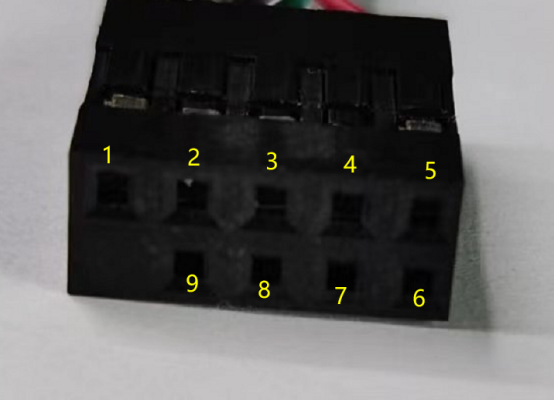
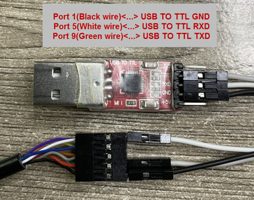
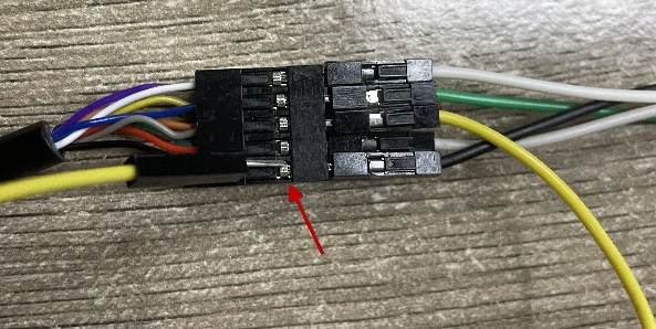
Step2: wiring method.
First connect the four lines;
 ,
,
Then use DuPont cable to short circuit port3 and port1, and then release them, so that the device enters bootlaod mode.
Step3: Select the device port to be connected, baud rate and bin file to be downloaded.
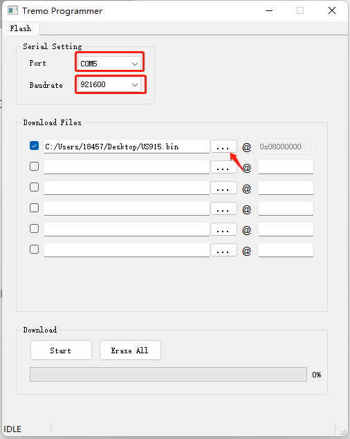
Click the start button to start the firmware upgrade.
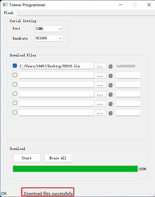
When this interface appears, it indicates that the download has been completed.
Finally, unplug the DuPont cable on port4, and then use the DuPont cable to short circuit port3 and port1 to reset the device.
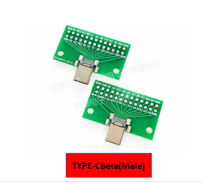
6.6 Using USB-TYPE-C to connect to the computer using the AT command
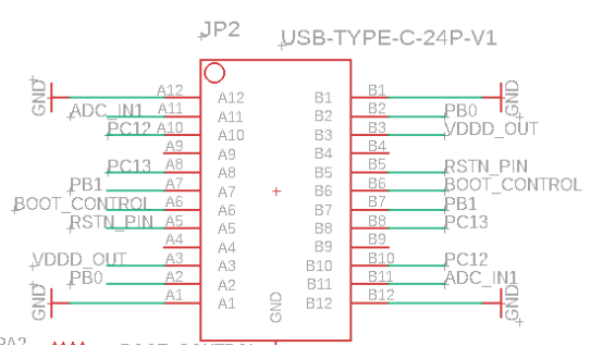
UART Port of LHT65N:
- PB0: RXD
- PB1: TXD
- GND

In PC, User needs to set serial tool(such as putty, SecureCRT) baud rate to 9600 to access to access serial console for LHT65N. The AT commands are disable by default and need to enter password (default:123456) to active it. Timeout to input AT Command is 5 min, after 5-minute, user need to input password again. User can use AT+DISAT command to disable AT command before timeout.
Input password and ATZ to activate LHT65N,As shown below:
6.7 How to use USB-TYPE-C to connect PC to upgrade firmware?
Step1: Install TremoProgrammer first.
Step2: wiring method.
First connect the four lines;

Connect A8 and GND with Dupont wire for a while and then separate, enter reset mode
Step3: Select the device port to be connected, baud rate and bin file to be downloaded.
Click the start button to start the firmware upgrade.
When this interface appears, it indicates that the download has been completed.
Finally,Disconnect 3.3v, Connect A8 and GND with Dupont wire for a while and then separate, exit reset mode
6.8 Why can't I see the datalog information
1. The time is not aligned, and the correct query command is not used.
2. Decoder error, did not parse the datalog data, the data was filtered.
7. Order Info
Part Number: LHT65N-XX-YY
XX : The default frequency band
- AS923: LoRaWAN AS923 band
- AU915: LoRaWAN AU915 band
- EU433: LoRaWAN EU433 band
- EU868: LoRaWAN EU868 band
- KR920: LoRaWAN KR920 band
- US915: LoRaWAN US915 band
- IN865: LoRaWAN IN865 band
- CN470: LoRaWAN CN470 band
YY: Sensor Accessories
- E3: External Temperature Probe
8. Packing Info
Package Includes:
- LHT65N Temperature & Humidity Sensor x 1
- Optional external sensor
Dimension and weight:
- Device Size: 10 x 10 x 3.5 mm
- Device Weight: 120.5g
9. Reference material
10. FCC Warning
This device complies with part 15 of the FCC Rules.Operation is subject to the following two conditions:
(1) This device may not cause harmful interference;
(2) this device must accept any interference received, including interference that may cause undesired operation.