LDS25-LB/LDS25-LS -- LoRaWAN LiDAR Distance Auto-Clean Sensor User Manual

Table of Contents :
- 1. Introduction
- 2. Registering LDS25-LB/LS with a LoRaWAN Network Server
- 3. Configure LDS25-LB/LS
- 4. Battery & Power Consumption
- 5. OTA Firmware update
- 6. FAQ
- 7. Troubleshooting
- 8. Order Information
- 9. Packing Information
- 10. Support
1. Introduction
1.1 What is LoRaWAN LiDAR Distance Auto-Clean Sensor
The Dragino LDS25-LB/LS is a LoRaWAN LiDAR (Time of Flight) Distance Auto-Clean Sensor for Internet of Things solution. It is capable to measure the distance to an object as close as 10 centimeters (+/- 6cm up to 6m) and as far as 25 meters (+/-1% starting at 25m)!. The LiDAR probe uses laser induction technology for distance measurement.
It has a unique dust removal brush structure built in, and the radar drives the dust removal brush to complete the optical mirror dust removal operation, and the user can customize the dust removal confguration.
The LDS25-LB/LS can be applied to scenarios such as horizontal distance measurement, parking management system, object proximity and presence detection, intelligent trash can management system, robot obstacle avoidance, automatic control, sewer, etc.
It detects the distance between the measured object and the sensor, and uploads the value via wireless to LoRaWAN IoT Server.
The LoRa wireless technology used in LDS25-LB/LS allows device to send data and reach extremely long ranges at low data-rates. It provides ultra-long range spread spectrum communication and high interference immunity whilst minimizing current consumption.
LDS25-LB/LS supports BLE configure and wireless OTA update which make user easy to use.
LDS25-LB/LS is powered by 8500mAh Li-SOCI2 battery or solar powered + Li-ion battery , it is designed for long term use up to 5 years.
Each LDS25-LB/LS is pre-load with a set of unique keys for LoRaWAN registrations, register these keys to local LoRaWAN server and it will auto connect after power on.
1.2 Features
- LoRaWAN 1.0.3 Class A
- Bands: CN470/EU433/KR920/US915/EU868/AS923/AU915/IN865
- Ultra-low power consumption
- Laser technology for distance detection
- Self-contained Auto-clean function
- Measure Distance: 0.1m~25m
- Accuracy : ±6cm@(0.1m-6m), ±1%@(6m-25m)
- Resolution : 1cm
- FOV : 3°
- Monitor Battery Level
- Support Bluetooth v5.1 and LoRaWAN remote configure
- Support wireless OTA update firmware
- AT Commands to change parameters
- Downlink to change configure
- 8500mAh Li/SOCl2 Battery (LDS25-LB)
- Solar panel + 3000mAh Li-ion battery (LDS25-LS)
1.3 Specification
Common DC Characteristics:
- Supply Voltage: Built-in Battery , 2.5v ~ 3.6v
- Operating Temperature: -40 ~ 85°C
Probe Specification:
- Storage temperature: -30℃~80℃
- Operating temperature : -20℃~60℃
- Measure Distance:
- 0.1m ~ 25m @ 90% Reflectivity
- 0.1m ~ 12m @ 10% Reflectivity
- Accuracy : ±6cm@(0.1m-6m), ±1%@(6m-25m)
- Distance resolution : 1cm
- Ambient light immunity : 100klux
- Enclosure rating : IP5X
- Light source : VCSEL
- Central wavelength : 850nm
- FOV : 3°
- Material of enclosure : ABS+PC
- Wire length : 120cm
LoRa Spec:
- Frequency Range, Band 1 (HF): 862 ~ 1020 Mhz
- Max +22 dBm constant RF output vs.
- RX sensitivity: down to -139 dBm.
- Excellent blocking immunity
Battery:
- Li/SOCI2 un-chargeable battery
- Capacity: 8500mAh
- Self-Discharge: <1% / Year @ 25°C
- Max continuously current: 130mA
- Max boost current: 2A, 1 second
Power Consumption
- Sleep Mode: 5uA @ 3.3v
- LoRa Transmit Mode: 125mA @ 20dBm, 82mA @ 14dBm
1.4 Applications
- Horizontal distance measurement
- Parking management system
- Object proximity and presence detection
- Intelligent trash can management system
- Robot obstacle avoidance
- Automatic control
- Sewer
1.5 Sleep mode and working mode
Deep Sleep Mode: Sensor doesn't have any LoRaWAN activate. This mode is used for storage and shipping to save battery life.
Working Mode: In this mode, Sensor will work as LoRaWAN Sensor to Join LoRaWAN network and send out sensor data to server. Between each sampling/tx/rx periodically, sensor will be in IDLE mode), in IDLE mode, sensor has the same power consumption as Deep Sleep mode.
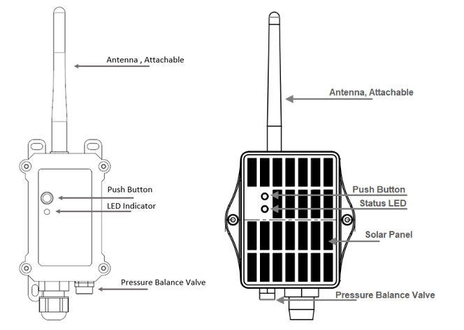
1.6 Button & LEDs
| Behavior on ACT | Function | Action |
|---|---|---|
 1~3s 1~3s | Send an uplink | If the sensor is already joined to a LoRaWAN network, it will send an uplink packet, and the blue LED will blink once. |
 >3s >3s | Active Device | The green LED will blink rapidly 5 times, and the device will enter OTAA mode for 3 seconds. It will then start joining the LoRaWAN network. |
 x5 x5 | Deactivate Device | The red LED will stay on for 5 seconds, indicating that the device is in Deep Sleep Mode. |
1.7 BLE connection
Bluetooth Low Energy (BLE) can be used to configure sensor parameters or view the console output from the sensor. The BLE module will only be activated in the following cases:
- When the button is pressed to send an uplink.
- When the button is pressed to activate the device.
- When the device is powered on or reset.
If there is no active BLE connection within 60 seconds, the sensor will shut down the BLE module to enter low-power mode.
1.8 Pin Definitions

1.9 Variants
LDS25 has two variants:
- LDS25-LB - 8500mAh Li/SOCl2 Battery
- LDS25-LS - Solar panel + 3000mAh Li-ion battery
1.10 Mechanical
1.10.1 for LB version
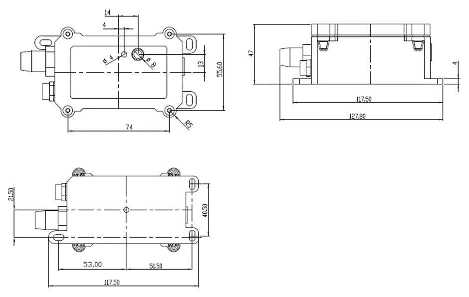
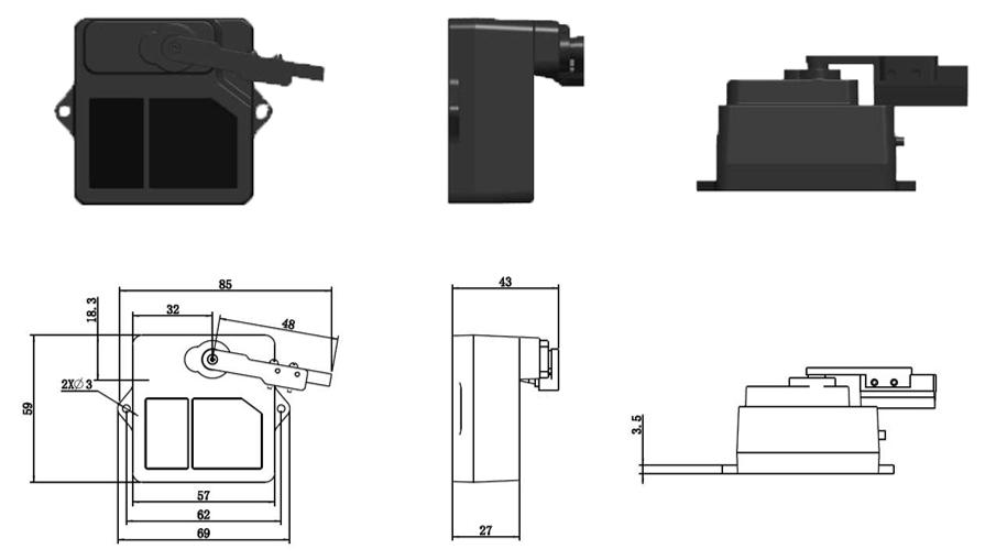
Probe Mechanical:
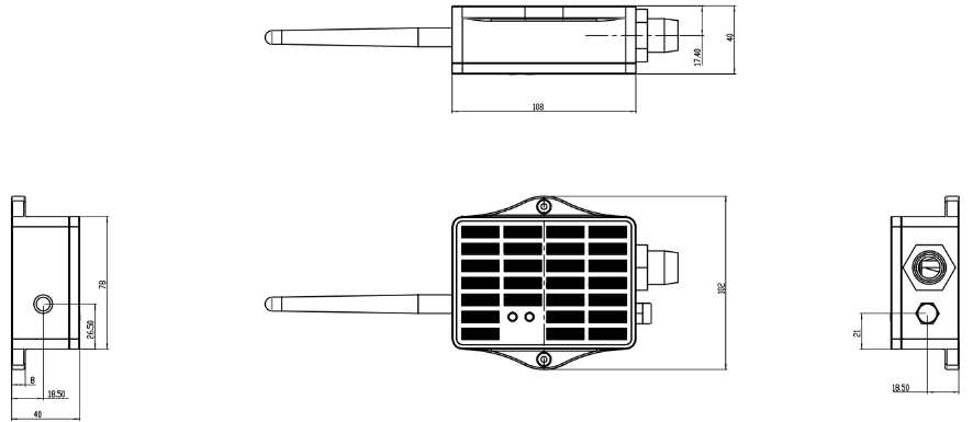
1.10.2 for LS version
2. Registering LDS25-LB/LS with a LoRaWAN Network Server
The LDS25-LB/LS can be registered with any LoRaWAN network server. In this documentation, we use The Things Stack as an example, but similar settings may apply to other LoRaWAN network servers.
2.1 How does the LDS25-LB/LS work?
The LDS25-LB/LS is configured in LoRaWAN Class A mode by default. The device ships with unique registration information that can be used to configure it for OTAA (Over-The-Air Activation).
To connect to a local LoRaWAN network, you must first register the device with the respective LoRaWAN network server using the registration information.
The LDS25-LB/LS's registration information can be found inside the device package.

The registration information includes the following:
- DevEUI
- AppEUI
- AppKey
We recommend using the OTAA activation method because it is more secure than the ABP method. After adding the registration information, press the ACT button to activate the LDS25-LB/LS. It will automatically join the network using OTAA and start sending sensor values. The default uplink interval is 20 minutes.
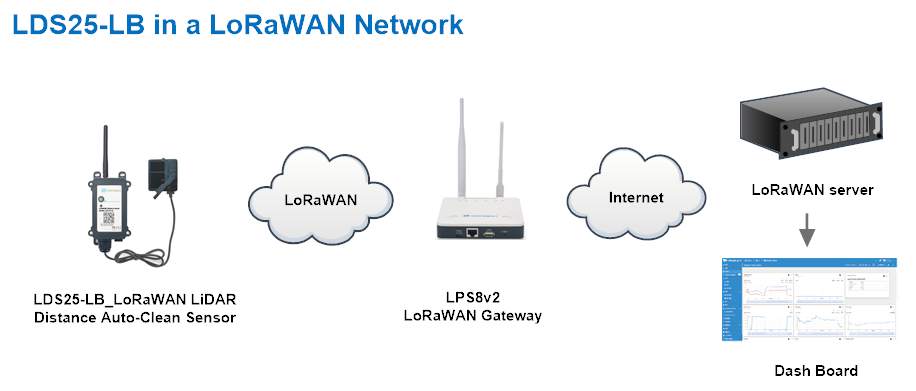
The following figure shows how end-to-end communication occurs between the LDS25-LB/LS and a typical LoRaWAN Network Server.
2.2 Registering with The Things Stack
In this section we will guide you through on how to register the LDS25-LB/LS with The Things Stack. If your area has The Things Stack community network coverage, you can use it without setting up your own network. If not, you can set up your own LoRaWAN network coverage by using our LPS8N LoRaWAN gateway.
The following figure shows the end-to-end network setup with the LDS25-LB/LS, the LPS8v2 LoRaWAN gateway, and The Things Stack LoRaWAN Network Server:

2.2.1 Add LDS25-LB/LS to The Things Stack
- Manually
2.2.1.1 Creating an application
Sign up for a free account with The Things Stack Sandbox if you do not have one yet. Then, create an application as shown in the screenshots below.


2.2.1.2 Adding using the LoRaWAN device repository
You can refer to the screenshots below to register your LDS25-LB/LS using The Things Stack's LoRaWAN device repository.
On The Things Stack console:
1. Click Applications.
2. Click the + button and then choose Register end device in an application form the drop-down list.
3. Select your application from the pop-up window.


On the Register end device page:
1. Select Enter end device specifies manually option.
2. Frequency plan: Select the frequency plan that matches your device. E.g.: Europe 863-870 MHz (SF9 for RX2 - recommended).
3. LoRaWAN version: LoRaWAN Specification 1.0.3
4. Regional Parameters version: You can't change it and it will select automatically.
5. JoinEUI: Enter the AppEUI of the device (see the registration information sticker) and Click the Confirm button.

6. DevEUI: Enter the DevEUI of the device (see the registration information sticker).
7. AppKey: Enter the AppKey of the device (see the registration information sticker).
8. End device ID: Enter a name for your end device to uniquely identify it within this application.
9. Click View registered end device option.
10. Click Register end device button.

You will be navigated to the Device overview page.
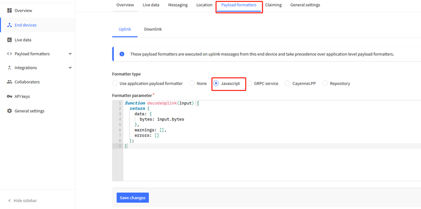
2.2.1.3 Uplink Decoder in The Things Stack
When the uplink payload arrives in The Things Stack, it is displayed in HEX format, which is not easy to read. You can add the LDS25-LB/LS decoder in The Things Stack for easier readability of each sensor readings.
The uplink decoder can be added to the Payload Formatters of your device in The Things Stack. Refer to the screenshot below.
1. Click Uplink tab.
2. Formatter type: Select Custom Javascript formatter.
3. Formatter code: Copy the uplink payload formatter code from our dragino-end-node-decoder GitHub repository and paste it here.
4. Finally, click on the Save changes button.


2.2.1.4 Activate the device by pressing and holding the ACT button for more than 5 seconds.
Press and hold the button for 5 seconds to activate the LDS25-LB/LS.
The green LED will blink rapidly 5 times, and the device will enter OTAA mode for 3 seconds. Then it will begin the LoRaWAN join procedure. Once successfully joined to the network, the green LED will stay on for 5 seconds.
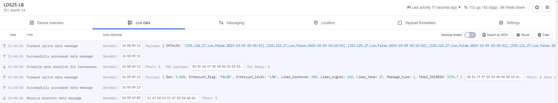
After a successful join, the device will start uploading messages to The Things Stack, and you will be able to see the messages in the panel.

2.3 Uplink Payload
2.3.1 Device Status, FPort=5
You can use the downlink command (0x26 01) to request the LDS25-LB/LS to send its configuration details, including the current configuration status. The LDS25-LB/LS will then uplink a payload via FPort=5 to the network server.
The Payload format is as below:
Size(bytes) | 1 | 2 | 1 | 1 | 2 |
|---|---|---|---|---|---|
| Value | Sensor Model | Firmware Version | Frequency Band | Sub-band | BAT |
Example payload in The Things Stack v3:

Sensor Model: For LDS25-LB/LS, this value is 0x3E
Firmware Version: 0x0100, which means v1.0.0
Frequency Band:
0x01: EU868
0x02: US915
0x03: IN865
0x04: AU915
0x05: KZ865
0x06: RU864
0x07: AS923
0x08: AS923-1
0x09: AS923-2
0x0a: AS923-3
0x0b: CN470
0x0c: EU433
0x0d: KR920
0x0e: MA869
Sub-Band:
AU915 and US915:value 0x00 ~ 0x08
CN470: value 0x0B ~ 0x0C
Other Bands: always 0x00
Battery Info:
Calculate the battery voltage as follows:
Battery Voltage (mV) = (High Byte × 256) + Low Byte
0x0C96 = 3222mV
More examples:
Example 1: 0x0B45 = 2885mV
Example 2: 0x0B49 = 2889mV
2.3.2 Uplink Payload, FPort=2
The LDS25-LB/LS will send this uplink after the Device Status message once it has successfully joined the LoRaWAN network.
It will then continue to send this uplink periodically every 20 minutes. This interval can be changed.
Uplink Payload: totals 11 bytes.
Size(bytes) | 2 | 2 | 2 | 2 | 1 | 1 | 1 |
|---|---|---|---|---|---|---|---|
| Value | BAT | Distance | Distance signal strength | LiDAR temp |

Battery Info:
Check the battery voltage for LDS25-LB/LS.
- Example 1: 0x0C72 = 3186mV
More examples:
- Example 2: 0x0B49 = 2889mV
DS18B20 Temperature sensor:
This is an optional 2 bytes field. You can connect an external DS18B20 sensor to the +3.3V, 1-Wire, and GND pins. This field will then report the temperature.
Example:
- If the payload is 0105H:
(0105H & FC00H == 0), therefore
temp = 0105H / 10 = 26.1°C
- If the payload is FF3FH:
(FF3FH & FC00H != 0), therefore
temp = (FF3FH - 65536) / 10 = -19.3°C
Distance:
Represents the measured distance value. The default unit is centimeters (cm), and the value range (parsed as a decimal number) is 0 to 2500. In actual use, the measurement may be affected by the signal strength value (Strength).
Example:
- If the data read from the register is 0x0B 0xEA, then the distance between the sensor and the measured object is:
0x0BEA (hex) = 3050 (decimal) / 10 = 305.0 cm
Distance signal strength:
This refers to the signal strength of the distance measurement. The default output value ranges from 0 to 65,535. When the measurement gear is fixed, the farther the target is, the lower the signal strength. Similarly, a target with lower reflectivity will also result in a lower signal strength. When the Strength value is greater than 100 and not equal to 65,535, the measured Distance value is considered reliable.
Example:
- If the payload is 016C(H) = 364 (decimal), then the distance signal strength is 364.
Since 364 > 100 and 364 ≠ 65,535, the measured Distance value is considered reliable.
Customers can use the signal strength value to determine whether the environment needs to be adjusted.
1) When the sensor detects valid data:

2) When the sensor detects invalid data:

3) When the sensor is not connected:

Interrupt Pin & Interrupt Level:
This data field indicates whether the packet was generated by an interrupt. Click here for details on the hardware and software setup.
Note: The Interrupt Pin is a dedicated pin on the screw terminal. See the GPIO_EXTI pin mapping for reference.
Example:
- If byte[0] & 0x01 = 0x00: Normal uplink packet
- If byte[0] & 0x01 = 0x01: Interrupt-generated uplink packet
LiDAR temp:
Represents the internal temperature of the sensor.
Example:
- If the payload is 1C(H), then ((1C << 24) >> 24) = 26 (decimal), so LiDAR temp = 26 °C
- If the payload is F2(H), then ((F2 << 24) >> 24) = -14 (decimal), so LiDAR temp = -14 °C
Message Type:
For a normal uplink payload, the message type is always set to 0x01.
Valid Message Type:
| Message Type Code | Description | Payload |
|---|---|---|
| 0x01 | Normal Uplink | Normal Uplink Payload |
| 0x02 | Reply configures info | Configure Info Payload |

2.3.3 Historical measuring distances, FPort=3
LDS25-LB/LS stores sensor values, and you can retrieve these historical values via a downlink command.
The historical payload includes one or multiple entries, and each entry has the same format as the real-time distance measurement payload.
Size(bytes) | 1 | 1 | 2 | 2 | 1 | 4 |
|---|---|---|---|---|---|---|
| Value | Interrupt flag & Interrupt_level | Reserve(0xFF) | Distance | Distance signal strength | LiDAR temp | Unix TimeStamp |
Interrupt flag & Interrupt level:
Size(bit) | bit7 | bit6 | [bit5:bit2] | bit1 | bit0 |
|---|---|---|---|---|---|
| Value | No ACK message | Poll Message Flag | Reserve | Interrupt level | Interrupt flag |
- Each data entry is 11 bytes and follows the same structure as the Uplink Payload. To save airtime and battery, the LDS25-LB/LS will send the maximum number of bytes allowed based on the current data rate (DR) and frequency band.
For example, in the US915 band, the maximum payload size for different data rates (DR) is as follows:
a) DR0: Maximum is 11 bytes, so one data entry is sent.
b) DR1: Maximum is 53 bytes, so the device uploads 4 data entries (total 44 bytes).
c) DR2: The total payload includes 11 data entries.
d) DR3: The total payload includes 22 data entries.
If the LDS25-LB/LS has no data available during the polling time, it will uplink 11 bytes of zero.
Downlink:
0x31 67 05 E4 CC 67 05 EA A8 05
Uplink:
40FF0CEE007E1B6705E50040FF0CB2007B1B6705E62C40FF0CA800811B6705E75840FF0CD0007C1B6705E88440FF0CE400791B6705E9B0
Parsed Value:
[DISTANCE , DISTANCE_SIGNAL_STRENGTH , LIDAR_TEMP , EXTI_STATUS , EXTI_FLAG , TIME]
[331,126,27,Low,False,2024-10-09 02:05:52],
[325,123,27,Low,False,2024-10-09 02:10:52],
[324,129,27,Low,False,2024-10-09 02:15:52],
[328,124,27,Low,False,2024-10-09 02:20:52],
[330,121,27,Low,False,2024-10-09 02:25:52],
[342,122,27,Low,False,2024-10-09 02:30:52],
[338,127,27,Low,False,2024-10-09 02:35:52],
[328,126,27,Low,False,2024-10-09 02:40:52]
History read from serial port:
2.3.4 Uplink after automatic cleaning, FPort=6 (Since firmware v1.2)
The LDS25-LB/LS sends this uplink after the automatic cleaning function is enabled.
Note: This is effective only if the d parameter is set to 1 in the command, AT+REMODUST=a,b,c,1
For example, with the command AT+REMODUST=1,1,5,1, the LDS25-LB/LS will perform a cleaning cycle every 5 minutes and send an uplink after each cleaning is complete.
The uplink payload is 8 bytes in total.
Size(bytes) | 1 | 1 | 2 | 4 |
|---|---|---|---|---|
| Value | Wiper_workmode | Wiper_clean_times | Wiper_clean_interval | Wiper_last_clean_time |
Example: AT+REMODUST=1,1,5,1

Wiper_workmode
This field displays the current cleaning mode.
0x01: "1" - Wiper cleaning is activated at regular intervals
Wiper_clean_times
This field shows the number of Wiper cleanings, with each round trip counted as 1.
Example 1: 0x01(H) = 1 time
Example 2: 0x03(H) = 3 times
Wiper_clean_interval
This field shows the automatic cleaning interval. (Unit: minutes)
Example 1: 0x00 05(H) = 5 minutes
Example 2: 0x03 84(H) = 900 minutes = 15hours
Wiper_last_clean_time
This field shows the start time of the last automatic cleaning.
Unit: Timestamp
Example: 67B45050(H) = 1739870288(D)
Paste the decimal value into this converter (https://www.epochconverter.com/https://www.epochconverter.com/) to get the human-readable time.
2.3.5 Decode payload in The Things Stack
When using The Things Stack (TTS), you can add a payload formatter to decode the payload.
The payload decoder function for The Things Stack is available here:
LDS25-LB/LS TTS Payload Decoder: https://github.com/dragino/dragino-end-node-decoder
2.4 Show Data in DataCake IoT Server
DATACAKE provides a human friendly interface to show the sensor data, once we have data in TTN, we can use DATACAKE to connect to TTN and see the data in DATACAKE. Below are the steps:
Step 1: Be sure that your device is programmed and properly connected to the network at this time.
Step 2: To configure the Application to forward data to DATACAKE you will need to add integration. To add the DATACAKE integration, perform the following steps:
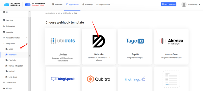
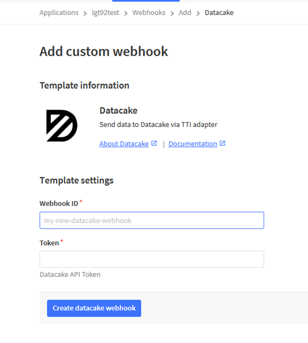
Step 3: Create an account or log in Datacake.
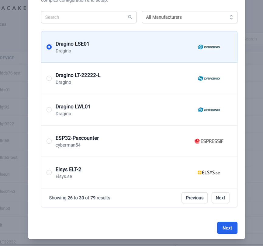
Step 4: Search the LDS25-LB/LS and add DevEUI.
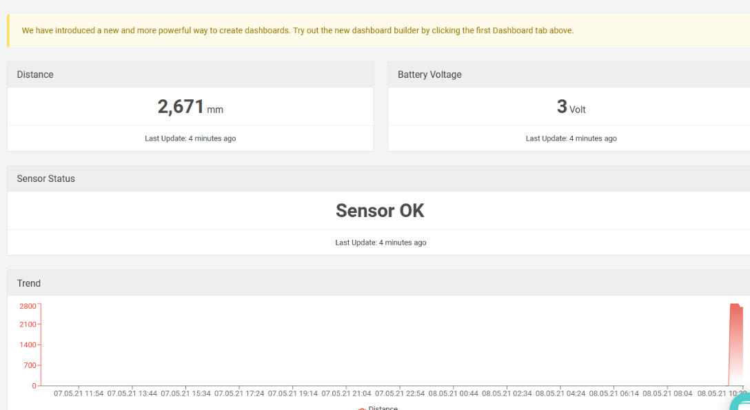
After added, the sensor data arrive TTN V3, it will also arrive and show in Datacake.
2.5 Integrating with IoT platforms
The LDS25-LB/LS sensor data can be integrated with other IoT platforms for better visualizing and analyzing the data. In this section, we will show you how to integrate sensor data from The Things Stack with some popular IoT platforms.
2.5.1 Integrate and show data on ThingsEye
The Things Stack application supports integration with ThingsEye.io. Once integrated, ThingsEye.io acts as an MQTT client for The Things Stack MQTT broker, allowing it to subscribe to upstream traffic and publish downlink traffic.
2.5.1.1 Configuring The Things Stack
We use The Things Stack Sandbox in this example:
- In The Things Stack Sandbox, go to the Application for the LDS25-LB/LS you added.
- Select MQTT under Integrations in the left menu.
- In the Connection information section, under Connection credentials, The Things Stack displays an auto-generated username. You can use it or provide a new one.
- Click the Generate new API key button to generate a password. You can view it by clicking on the visibility toggle/eye icon. The API key works as the password.

2.5.1.2 Configuring ThingsEye.io
The ThingsEye.io IoT platform is not open for self-registration at the moment. If you are interested in testing the platform, please send your project information to admin@thingseye.io, and we will create an account for you.
- Login to your ThingsEye.io account.
- Under the Integrations center, click Integrations.
- Click the Add integration button (the button with the + symbol).

On the Add integration window, configure the following:
Basic settings:
- Select The Things Stack Community from the Integration type list.
- Enter a suitable name for your integration in the Name text box or keep the default name.
- Ensure the following options are turned on.
- Enable integration
- Debug mode
- Allow create devices or assets
- Click the Next button. you will be navigated to the Uplink data converter tab.

Uplink data converter:
- Click the Create new button if it is not selected by default.
- Enter a suitable name for the uplink data converter in the Name text box or keep the default name.
- Click the JavaScript button.
- Paste the uplink decoder function into the text area (first, delete the default code). The demo uplink decoder function can be found here.
- Click the Next button. You will be navigated to the Downlink data converter tab.

Downlink data converter (this is an optional step):
- Click the Create new button if it is not selected by default.
- Enter a suitable name for the downlink data converter in the Name text box or keep the default name.
- Click the JavaScript button.
- Paste the downlink decoder function into the text area (first, delete the default code). The demo downlink decoder function can be found here.
- Click the Next button. You will be navigated to the Connection tab.

Connection:
- Choose Region from the Host type.
- Enter the cluster of your The Things Stack in the Region textbox. You can find the cluster in the url (e.g., https://eu1.cloud.thethings.network/...).
- Enter the Username and Password of the MQTT integration in the Credentials section. The username and password can be found on the MQTT integration page of your The Things Stack account (see 2.5.1.1 Configuring The Things Stack).
- Click the Check connection button to test the connection. If the connection is successful, you will see the message saying Connected.

Click the Add button.

Your integration has been added to the Integrations list and will be displayed on the Integrations page. Check whether the status is shown as Active. If not, review your configuration settings and correct any errors.

2.5.1.3 Viewing integration details
Click on your integration from the list. The Integration details window will appear with the Details tab selected. The Details tab shows all the settings you have provided for this integration.

If you want to edit the settings you have provided, click on the Toggle edit mode button. Once you have done click on the Apply changes button.
2.5.1.4 Viewing events
The Events tab displays all the uplink messages from the LDS25-LB/LS.
- Select Debug from the Event type dropdown.
- Select the time frame from the time window.

- To view the JSON payload of a message, click on the three dots (...) in the Message column of the desired message.

2.5.1.5 Viewing Sensor data on a dashboard
You can create a dashboard with ThingsEye to visualize the sensor data coming from the LDS25-LB/LS. The following image shows a dashboard created for the LDS25-LB/LS. See Creating a dashboard in ThingsEye documentation for more information.

2.5.1.6 Deleting an integration
If you want to delete an integration, click the Delete integration button on the Integrations page.
2.6 Datalog Feature
Datalog Feature is to ensure IoT Server can get all sampling data from Sensor even if the LoRaWAN network is down. For each sampling, LDS25-LB/LS will store the reading for future retrieving purposes.
2.6.1 How datalog works
LDS25-LB/LS will wait for ACK for every uplink, when there is no LoRaWAN network,LDS25-LB/LS will mark these records with non-ack messages and store the sensor data, and it will send all messages (10s interval) after the network recovery.
a) LDS25-LB/LS will do an ACK check for data records sending to make sure every data arrive server.
b) LDS25-LB/LS will send data in CONFIRMED Mode, but LDS25-LB/LS won't re-transmit the packet if it doesn't get ACK, it will just mark it as a NONE-ACK message. In a future uplink if LDS25-LB/LS gets a ACK, LDS25-LB/LS will consider there is a network connection and resend all NONE-ACK messages.
2.6.2 Enable Datalog
User need to make sure below two settings are enable to use datalog;
- SYNCMOD=1(Default) to enable sync time via LoRaWAN MAC command, click here (AT+SYNCMOD) for detailed instructions.
- PNACKMD=1 to enable datalog feature, click here (AT+PNACKMD) for detailed instructions.
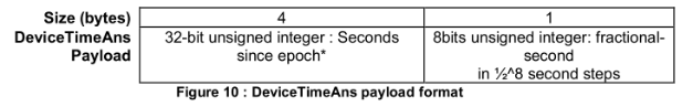
Once LDS25-LB/LS Joined LoRaWAN network, it will send the MAC command (DeviceTimeReq) and the server will reply with (DeviceTimeAns) to send the current time to LDS25-LB/LS. If LDS25-LB/LS fails to get the time from the server, LDS25-LB/LS will use the internal time and wait for next time request (AT+SYNCTDC to set the time request period, default is 10 days).
Note: LoRaWAN Server need to support LoRaWAN v1.0.3(MAC v1.0.3) or higher to support this MAC command feature, Chirpstack,TTN V3 v3 and loriot support but TTN V3 v2 doesn't support. If server doesn't support this command, it will through away uplink packet with this command, so user will lose the packet with time request for TTN V3 v2 if SYNCMOD=1.
2.6.3 Unix Timestamp
LDS25-LB/LS uses Unix Timestamp format based on the following:
You can get the Unix timestamp from the following link: https://www.epochconverter.com/ :
Below is an example using the Code Beauty - Decimal to Hex converter.
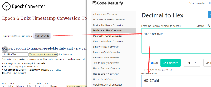
So, we can use AT+TIMESTAMP=1611889405 or downlink 3060137afd00 to set the current time 2021 – Jan -- 29 Friday 03:03:25
2.6.4 Poll sensor value
Users can poll sensor values based on timestamps. Below is the downlink command.
| Downlink Command to poll Open/Close status (0x31) | |||
| 1byte | 4bytes | 4bytes | 1byte |
| 31 | Timestamp start | Timestamp end | Uplink Interval |
Timestamp start and Timestamp end-use Unix TimeStamp format as mentioned above. Devices will reply with all data logs during this period, using the uplink interval.
For example, downlink command 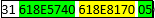
Is to check 2021/11/12 12:00:00 to 2021/11/12 15:00:00's data
Uplink Internal =5s, means LDS25-LB/LS will send one packet every 5s. range 5~255s.
2.7 Frequency Plans
The LDS25-LB/LS uses OTAA mode and below frequency plans by default. Each frequency band use different firmware, user update the firmware to the corresponding band for their country.
http://wiki.dragino.com/xwiki/bin/view/Main/End%20Device%20Frequency%20Band/
2.8 LiDAR ToF Measurement
2.8.1 Principle of Distance Measurement
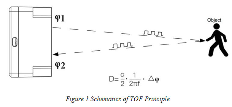
The LiDAR probe is based on TOF, namely, Time of Flight principle. To be specific, the product emits modulation wave of near infrared ray on a periodic basis, which will be reflected after contacting object. The product obtains the time of flight by measuring round-trip phase difference and then calculates relative range between the product and the detection object, as shown below.
2.8.2 Distance Measurement Characteristics
With optimization of light path and algorithm, The LiDAR probe has minimized influence from external environment on distance measurement performance. Despite that, the range of distance measurement may still be affected by the environment illumination intensity and the reflectivity of detection object.
TF02-Pro-W Detection Angle Diagram:

Vertical Coordinates: Represents the radius of light spot for The LiDAR probe at different distances. The diameter of light spot depends on the FOV of The LiDAR probe (the term of FOV generally refers to the smaller value between the receiving angle and the transmitting angle), which is calculated as follows:
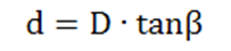
In the formula above, d is the diameter of light spot; D is detecting range; β is the value of the receiving angle of The LiDAR probe, 3°. Correspondence between the diameter of light spot and detecting range is given in Table below.

If the light spot reaches two objects with different distances, as shown in Figure 3, the output distance value will be a value between the actual distance values of the two objects. For a high accuracy requirement in practice, the above situation should be noticed to avoid the measurement error.
2.8.3 Notes on usage
Possible invalid or incorrect readings with LiDAR ToF technology:
- Measuring high-reflectivity objects such as mirrors, smooth ceramic tiles, or static milk surfaces may result in incorrect readings.
- If there are transparent objects such as glass or water droplets between the measured object and the LiDAR sensor, the readings may be inaccurate.
- If the LiDAR probe is covered with dirt or debris, the readings may be incorrect. In this case, clean the probe.
- The sensor window is made of acrylic. Do not touch it with alcohol-based substances, as this may damage the window.
2.8.4 Reflectivity of different objects
| Item | Material | Reflectivity |
|---|---|---|
| 1 | Black foam rubber | 2.4% |
| 2 | Black fabric | 3% |
| 3 | Black rubber | 4% |
| 4 | Coal (different types of coal) | 4~8% |
| 5 | Black car paint | 5% |
| 6 | Black Jam | 10% |
| 7 | Opaque black plastic | 14% |
| 8 | Clean rough board | 20% |
| 9 | Translucent plastic bottle | 62% |
| 10 | Carton cardboard | 68% |
| 11 | Clean pine | 70% |
| 12 | Opaque white plastic | 87% |
| 13 | White Jam | 90% |
| 14 | Kodak Standard Whiteboard | 100% |
| 15 | Unpolished white metal surface | 130% |
| 16 | Glossy light metal surface | 150% |
| 17 | stainless steel | 200% |
| 18 | Reflector plate, reflective tape | >300% |
3. Configure LDS25-LB/LS
3.1 Configure Methods
LDS25-LB/LS supports the following configuration methods:
- AT Commands via Bluetooth Connection (Recommended): BLE Configure Instruction.
- AT Commands via UART Connection : See UART Connection.
- LoRaWAN Downlinks. Instruction for different platforms: See IoT LoRaWAN Server section.
3.2 General Commands
These general commands are used to configure:
- General system settings, such as the uplink interval.
- LoRaWAN protocol and radio-related command.
They are the same for all Dragino devices that support the DLWS-005 LoRaWAN stack. You can find these commands on the wiki:
http://wiki.dragino.com/xwiki/bin/view/Main/End%20Device%20AT%20Commands%20and%20Downlink%20Command/
3.3 Commands specially designed for LDS25-LB/LS
These commands are only valid for the LDS25-LB/LS, as listed below:
3.3.1 Set Transmit (uplink) Interval Time
Feature: Change the LoRaWAN End Node Transmit (uplink) Interval.
AT Command: AT+TDC
| Command Example | Function | Response |
|---|---|---|
| AT+TDC=? | Get current transmit (uplink) Interval | 30000 |
| AT+TDC=60000 | Set Transmit (uplink) Interval | OK |
Downlink Command: 0x01
Format: Command code (0x01) followed by a 3-byte time value.
For example, if the downlink payload is 0100003C, it means the end node's transmit interval is set to 0x00003C = 60 seconds. The type code is 0x01.
- Example 1:
Downlink Payload: 0100001E
// Sets the transmit interval (TDC) to 30 seconds
- Example 2:
Downlink Payload: 0100003C
// Sets the transmit interval (TDC) to 60 seconds
3.3.2 Set Interrupt Mode
Feature: Sets the interrupt mode for the GPIO_EXTI pin.
When AT+INTMOD=0 is set, GPIO_EXTI functions as a digital input port.
AT Command: AT+INTMOD
| Command Example | Function | Response |
|---|---|---|
| AT+INTMOD=? | Get current interrupt mode | 0 |
AT+INTMOD=2 (default) | Set interrupt mode. | OK |
Downlink Command: 0x06
Format: Command code (0x06) followed by 3 bytes.
This sets the interrupt mode of the end node. For example, a value of 0x000003 means the interrupt mode is set to 3 (rising edge trigger). The type code is 0x06.
- Example 1:
Downlink Payload: 06000000
// Turns off interrupt mode
- Example 2:
Downlink Payload: 06000003
// Sets the interrupt mode to rising edge trigger
3.3.3 Set Power Output Duration
Control the output duration of 3v3 (VBAT_OUT pin). Before each sampling, the device will:
1. First, enable the power output to the external sensor.
2. Keep it on for the configured duration, read the sensor value, and construct the uplink payload.
3. Finally, turn off the power output.
AT Command: AT+3V3T
| Command Example | Function | Response |
|---|---|---|
| AT+3V3T=? | Get 3V3 open time. | 0 (default) OK |
| AT+3V3T=1000 | Turn off after a delay of 1000 milliseconds. | OK |
| AT+3V3T=0 | Always turn on the power supply of 3V3 pin. | OK |
| AT+3V3T=65535 | Always turn off the power supply of 3V3 pin. | OK |
Downlink Command: 0x07
Format: Command Code (0x07) followed by 3 bytes.
The first byte is 01. The second and third bytes are the time to turn on.
- Example 1: Downlink Payload: 07 01 00 00 ---> AT+3V3T=0
- Example 2: Downlink Payload: 07 01 01 F4 ---> AT+3V3T=500
- Example 3: Downlink Payload: 07 01 FF FF ---> AT+3V3T=65535
3.3.4 Get or set the automatic cleaning interval
Function: This setting allows the device to perform auto-cleaning either once before each uplink packet or at regular intervals. (Unit: minutes)
Note: If you set the device to automatically clean before every uplink, it will reduce the lifespan of the silicone on the wipers used by the sensors. Therefore, it is recommended to configure the wipers to activate once per day. (The factory default is one activation every 1440 minutes)
AT Command: AT+REMODUST
| Command Example | Function | Response |
|---|---|---|
| AT+REMODUST=? | Get automatic cleaning interval. | 1,1,1440,0 |
AT+REMODUST=1,1,720,1 | Set the purge function to run every 12 hours and send one uplink packet after the purge is complete. | OK |
AT+REMODUST=2,1,0,0 | Start the cleaning function once before sending each packet. | OK |
AT+REMODUST=2,2,0,0 | Start the cleaning function twice before sending each packet. | OK |
| AT+REMODUST | Start the cleaning function once immediately. | OK |
| Command Example | Function | parameters |
|---|---|---|
AT+REMODUST=a,b,c,d
| a: Set the cleaning brush run interval or trigger conditions. | 1: Timed start (parameter cc controls the interval); |
| b: Number of cleanings per activation. | Max. : 10 | |
| c: How often to start at regular intervals. | Unit: minutes | |
| d: Whether to send a packet after the scrubber brush has finished running. | 0: Uplink a packet after cleaning |
Downlink Command: 0x08 02
Format: Command Code (0x08 02) followed by 5 bytes.
- Example 1: Downlink Payload: 08 02 01 01 05 A0 00 ---> AT+REMODUST=1,1,1440,0
- Example 2: Downlink Payload: 08 02 01 01 02 D0 01 ---> AT+REMODUST=1,1,720,1
- Example 3: Downlink Payload: 08 02 02 01 00 00 00 ---> AT+REMODUST=2,1,0,0
- Example 4: Downlink Payload: 08 02 02 02 00 00 00 ---> AT+REMODUST=2,2,0,0
- Example 5: Downlink Payload: 08 01 ---> AT+REMODUST
3.3.5 Print data entries by page
Feature: Print sector data from the start page to the stop page (maximum: 416 pages).
AT Command: AT+PDTA
| Command Example | Function |
AT+PDTA=1,1 | Stop Tx events while reading sensor data. 8031000 1970/1/1 00:00:13 bat:3216 distance:327 strength:32767 temp:0 level:low status:false 8031010 1970/1/1 00:00:21 bat:3222 distance:327 strength:32767 temp:0 level:low status:false 8031020 1970/1/1 00:00:07 bat:3624 distance:327 strength:32767 temp:0 level:low status:false 8031030 1970/1/1 00:00:07 bat:3618 distance:327 strength:32767 temp:0 level:low status:false 8031040 2024/10/19 02:47:21 bat:3240 distance:0 strength:0 temp:0 level:low status:false 8031050 1970/1/1 00:00:17 bat:3252 distance:0 strength:0 temp:0 level:low status:false 8031060 2024/10/19 03:05:38 bat:3246 distance:0 strength:0 temp:0 level:low status:false 8031070 2024/10/19 03:16:19 bat:3258 distance:0 strength:15534 temp:0 level:low status:false Start Tx events OK |
Downlink Command:
No downlink commands are available for this feature.
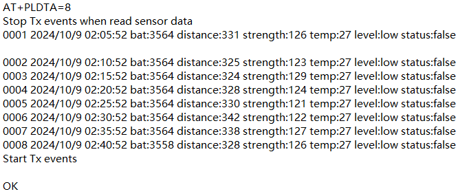
3.3.6 Print last few data entries
Feature: Prints the most recent data entries.
AT Command: AT+PLDTA
| Command Example | Function |
AT+PLDTA=10 | Stop Tx events while reading sensor data. 0001 2024/12/6 06:03:41 bat:3588 distance:0 strength:153 temp:26 level:low status:false 0002 2024/12/6 06:13:38 bat:3588 distance:66 strength:13986 temp:27 level:low status:false 0003 2024/12/6 06:23:38 bat:3588 distance:66 strength:14128 temp:26 level:low status:false 0004 2024/12/6 06:33:38 bat:3588 distance:66 strength:14100 temp:25 level:low status:false 0005 2024/12/6 06:43:38 bat:3588 distance:349 strength:123 temp:26 level:low status:false 0006 2024/12/6 06:53:38 bat:3588 distance:356 strength:124 temp:25 level:low status:false 0007 2024/12/6 07:03:38 bat:3588 distance:343 strength:114 temp:25 level:low status:false 0008 2024/12/6 07:13:38 bat:3588 distance:351 strength:122 temp:25 level:low status:false 0009 1970/1/1 00:00:25 bat:3258 distance:0 strength:65534 temp:0 level:low status:false 0010 1970/1/1 00:01:02 bat:3258 distance:0 strength:65534 temp:0 level:low status:false Start Tx events OK |
Downlink Command:
No downlink commands are available for this feature.
3.3.7 Clear Flash Record
Feature: Clears the flash storage used for the data logging feature.
AT Command: AT+CLRDTA
| Command Example | Function | Response |
| AT+CLRDTA | Clear data records | Clear all stored sensor data. OK |
Downlink Command: 0xA3
- Example: 0xA301 // Same as AT+CLRDTA
4. Battery & Power Consumption
The LDS25-LB uses an ER26500 + SPC1520 battery pack, while the LDS25-LS uses a 3000 mAh rechargeable battery with a solar panel.
See the link below for detailed information about the battery and replacement instructions.
Battery Info & Power Consumption Analyze .
5. OTA Firmware update
User can change firmware LDS25-LB/LS to:
- Change Frequency band/ region.
- Update with new features.
- Fix bugs.
Firmware and changelog can be downloaded from : Firmware download link
Methods to Update Firmware:
- (Recommanded way) OTA firmware update via wireless: http://wiki.dragino.com/xwiki/bin/view/Main/Firmware%20OTA%20Update%20for%20Sensors/
- Update through UART TTL interface: Instruction.
6. FAQ
6.1 What is the frequency plan for LDS25-LB/LS?
The LDS25-LB/LS use the same frequency as other Dragino products. User can see the detail from this link: Introduction
7. Troubleshooting
7.1 AT Command input doesn't work
If you can see the console output but cannot type input to the device, please check whether you are including the ENTER key when sending the command. Some serial tools do not send an ENTER automatically when you press the send button, so you may need to manually add it to your input string.
7.2 Significant error between the LiDAR output distance value and the actual distance
Cause ①:Due to the physical principles of the LiDAR probe, this issue may occur when the detected object has high reflectivity (e.g., mirrors, smooth floor tiles) or is a transparent substance (e.g., glass, water).
Troubleshooting: Avoid using the product under such conditions in practice.
Cause ②: The IR-pass filters are blocked.
Troubleshooting: Gently clean the filter using a dry, dust-free cloth to remove any foreign matter.
8. Order Information
Part Number: LDS25-LB-XX or LDS25-LS-XX
XX: The default frequency band
- AS923: LoRaWAN AS923 band
- AU915: LoRaWAN AU915 band
- EU433: LoRaWAN EU433 band
- EU868: LoRaWAN EU868 band
- KR920: LoRaWAN KR920 band
- US915: LoRaWAN US915 band
- IN865: LoRaWAN IN865 band
- CN470: LoRaWAN CN470 band
9. Packing Information
Package Includes:
- LDS25-LB or LDS25-LS LoRaWAN LiDAR ToF Distance Sensor x 1
Dimension and weight:
Package Size / pcs :
- For LDS25-LB: 195*125*55 mm
- For LDS25-LS: 210*110*10 mm
Weight / pcs : about 400 g
10. Support
- Support is available Monday to Friday, from 09:00 to 18:00 (GMT+8). Due to time zone differences, live support is not available. However, your questions will be answered as soon as possible within the stated support hours.
- Please provide as much information as possible regarding your inquiry, such as product models, a detailed description of the issue, and the steps to reproduce it, and send an email to Support@dragino.cc.