LC01 -- LoRaWAN Relay User Manual

Table of Contents:
- 1. Introduction
- 2. Configure LC01 to connect to LoRaWAN network
- 3. Configure LC01
- 4. OTA Firmware update
- 5. FAQ
- 6. Order Info
- 7. Packing Info
- 8. Support
1. Introduction
1.1 What is LC01 LoRaWAN Relay
The Dragino LC01 is a LoRaWAN®-enabled relay controller designed for smart control of electrical appliances and lighting. Ideal for remote switching and status monitoring, the LC01 is built to deliver reliable performance in demanding environments.
Key Features:
- Wide Voltage Support: Compatible with appliances operating from 80–275V AC, with a maximum resistive load of 15A.
- Dual Terminal Design: Equipped with two input and two output terminals for easy power connection.
- LoRaWAN® Class C: Operates in Class C mode for low-latency communication and continuous listening.
Built-In Protection & Durability:
- Advanced Safety: Integrated protection against overcurrent, overvoltage, short circuits, and temperature rise, helping reduce the risk of damage from lightning strikes.
- Rugged Enclosure: Made from fireproof PC material with UV-resistant additives, ensuring long-term durability without discoloration.
Plug & Play Connectivity:
- Preloaded Credentials: Comes with a unique DevEUI, AppEUI, and AppKey, enabling fast and secure registration on any LoRaWAN network.
- Auto Join Capability: Automatically connects to the pre-registered network once powered on.
Longer Life with Zero-Crossing Trigger:
- The LC01 includes a patented zero-crossing trigger, which minimizes electrical stress and extends the device’s operational life.
1.2 Features
- Frequency Bands: CN470/EU433/KR920/US915/EU868/AS923/AU915/RU864/IN865/MA869
- Dual Terminal Design: Equipped with two input and two output terminals for easy power connection.
- LoRaWAN® Class C: Operates in Class C mode for low-latency communication and continuous listening.
- Receiver on/ off times 400,000 times
- Log function and key reset function
- AT Commands to change parameters
- Remotely configure parameters via LoRaWAN Downlink
- Firmware upgradable via program port
- Uplink on periodically
- Downlink to change configure
1.3 Specification
Common DC Characteristics:
- Supply Voltage: 80-275V AC
- Operating Temperature: -40~+70°C
Current : 15A Resistive load
LoRa Spec:
- Frequency Range, Band 1 (HF): 862 ~ 1020 Mhz
- Max +22 dBm constant RF output vs.
- RX sensitivity: down to -139 dBm.
- Excellent blocking immunity
1.4 Applications
- Smart buildings & home automation
- Logistics and supply chain management
- Smart metering
- Smart agriculture
- Smart cities
- Smart factory
1.5 Working mode
Working Mode: In this mode, Sensor will work as LoRaWAN Sensor to Join LoRaWAN network and send out sensor data to server. Between each sampling/tx/rx periodically, sensor will be in IDLE mode).
1.6 Button & LEDs

| Behavior on ACT | Function | Action |
|---|---|---|
 >5s >5s | Active Device | The Red LED will blink rapidly 4 seconds. The device will then enter Bootloader mode for 5 seconds, and afterward, start joining the LoRaWAN network. |
1.7 Mechanical

2. Configure LC01 to connect to LoRaWAN network
2.1 How it works
The LC01 is configured as LoRaWAN OTAA Class C mode by default. It has OTAA keys to join LoRaWAN network. To connect a local LoRaWAN network, you need to input the OTAA keys in the LoRaWAN IoT server and press the button to activate the LC01. It will automatically join the network via OTAA and start to send the sensor value. The default uplink interval is 1 hour.
2.2 Quick guide to connect to LoRaWAN server (OTAA)
The following network diagram shows how LC01 communicates with a LoRaWAN Network Server, for example TTN v3 LoRaWAN Network. We use the LPS8N as a LoRaWAN gateway in this example and ThingsEye as the IoT platform.

Step 1: Create a device in The Things Stack with the OTAA keys from LC01.
Each LC01 is shipped with a unique DevEUI, AppEUI, and AppKey. You can find it inside the package of the device. Please keep your registration information in a safe place and don't share with anyone.

You can enter this key in the LoRaWAN Network Server portal.
The following steps describe how to do it with The Things Stack network server portal. Follow the screenshots for correct configuration:
Create an application.
- On the home screen, click the + Add application button.
- On the Create application page, enter an Application ID to identify your application within The Things Stack and provide an Application name. Read https://thethingsindustries.com/docs/integrations/adding-applications for more information on how to do that.
- Click the Create application button.

Add devices to the created Application
- After creating the application, you will be redirected to the Application overview page.
- On the Application overview page, click the + Register end device button.


Enter end device specifics manually
We use Over The Air Activation (OTAA) to activate LC01 with The Things Stack. OTAA is the most secure way of activating an end device with a LoRaWAN network server.
- On the Register end device page, select the ‘Enter end device specifics manually’ option under the input method.
- Select the correct Frequency plan and LoRaWAN version. The Regional parameters version will appear automatically based on the LoRaWAN version.
- Make sure the Over the air activation (OTAA) is selected by default.
- Select Class C (Continuous) from the Additional LoRaWAN class capabilities dropdown list.

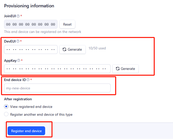
Using the registration information sheet that comes with the LC01,
- Fill the JoinEUI. The LC01 uses AppEUI instead of JoinEUI. You can enter it in the JoinEUI text box. Then click the Confirm button.
- Enter the DevEUI and AppKey.
- Enter an End device ID that can be used to identify your LC01 within this application.
Click the Register end device button.
Step 2: Add decoder.
LoRaWAN uplink and downlink payloads are encoded. To understand the data, you need a small script to decode them. We use a JavaScript function for this. It is called a payload formatter. It reads the payload and extracts useful information, such as relay status, event type, and timestamp. We have written a JavaScript function to decode uplinks from the LC01 device.
To add an uplink payload formatter code to The Things Stack, follow the steps below:
- Go to your LC01 device page and click Payload formatters.
- Click, Uplink.
- Select ‘Custom Javascript formatter’ from the ‘Formatter type’ drop-down list.
- Now copy the Uplink Formatter code from here: dragino-end-node-decoder/LC01/LC01_V1.0.0_TTN_Decoder.txt at main · dragino/dragino-end-node-decoder · GitHub
- Then paste it in the ‘Formatter code’ box:

You can now test the formatter code with a sample payload.
- Enter 00 00 00 06 03 00 in the ‘Byte payload’ box.
- Change the FPort to 2 (because our payload formatter only accepts uplinks from FPort 2).
- Click the ‘Test decoder’ button.
The payload will be decoded into the following JSON object and shown in the 'Decoded test payload' box.
To save the payload formatter, click the ‘Save changes’ button.

After applying the uplink payload formatter, you can see that all uplink payloads shown in the Live Data section are decoded into fields.
Step 3: Activate on LC01
Press the reset button once to activate the LC01.
Red led will fast blink 5 times, device will enter bootloader mode for 5 seconds. And then start to JOIN LoRaWAN network. Red led will solidly turn on for 5 seconds after joined in network.
After join success, it will start to upload messages to TTN and you can see the messages in the panel.
2.3 Uplink Payload
2.3.1 Device Status, FPort=5
You can use the downlink command 0x26 01 to request LC01 to send the device configuration details, including the configuration status. LC01 will then uplink a payload to the server via FPort 5. The payload format is shown below.
| Device Status (FPort=5) | |||||
| Size (bytes) | 1 | 2 | 1 | 1 | |
| Value | Sensor Model | Firmware Version | Frequency Band | Sub-band | |
This is an example of a payload parsed in The Things Stack.
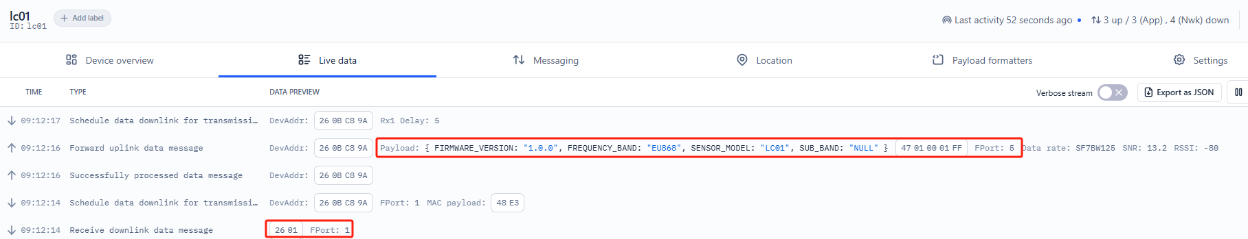
Sensor Model: For LC01, this value is 0x47
Firmware Version: 0x0100, which means version v1.0.0
Frequency Band:
0x01: EU868
0x02: US915
0x03: IN865
0x04: AU915
0x05: KZ865
0x06: RU864
0x07: AS923
0x08: AS923-1
0x09: AS923-2
0x0a: AS923-3
0x0b: CN470
0x0c: EU433
0x0d: KR920
0x0e: MA869
Sub-Band:
AU915 and US915: value 0x00 ~ 0x08
CN470: value 0x0B ~ 0x0C
Other bands: Always 0x00
2.3.2 Sensor Data, FPort=2
Sensor data is uplinked via FPort 2
Size(bytes) | 4 | 1 | 1 |
|---|---|---|---|
| Value | Unix Timestamp | EventType | RelayStatus |

Unix timestamp
Unix Timestamp Example: 681EAB65(H) = 1746840421(D)
Paste the decimal value into this link (https://www.epochconverter.com)) to convert it to human-readable time.
Event
Example:
If the payload is: 01H: PLUG_INSERT_EVENT
If the payload is: 02H : PLUG_PULL_EVENT
If the payload is: 03H : HEARTBEAT_EVENT
If the payload is: 04H : RELAY_ACK_EVENT
Relay status
Example:
If the payload is: 01H: Relay is 'open'.
If the payload is: 00H: Relay is 'closed'.
2.4 Payload Decoder
In The Things Stack, you can add a custom payload decoder to convert the raw payload into human-readable fields.
To do this go to: Applications --> Payload Formats --> Custom --> Decoder and add the decoder code from the following link:
https://github.com/dragino/dragino-end-node-decoder/tree/main/LC01
2.5 Datalog Feature
The Datalog feature ensures that the IoT server can receive all sampled data from the sensor, even if the LoRaWAN network is temporarily unavailable. For each sampling event, the LC01 stores the reading for future retrieval.
2.5.1 Retrieving Datalog via LoRaWAN
Using the platform downlink 07 01, you can enable the device to automatically send non-ACK messages. Once enabled, the LC01 will wait for an acknowledgment (ACK) for every uplink. If there is no LoRaWAN network available, LC01 will mark these records as non-ACK messages, store the sensor data, and continue checking for network availability (at 10-second intervals) to resend all stored messages once the network is restored.
a) LC01 performs an ACK check for each data record to ensure it successfully reaches the server.
b) When automatic sending of non-ACK messages is enabled, the LC01 transmits data in CONFIRMED mode. If an ACK is not received, it does not resend the packet; instead, it marks it as a non-ACK message. During subsequent uplinks, if the LC01 receives an ACK, it considers the network restored and will resend all stored non-ACK messages.
2.5.2 Unix TimeStamp
LC01 uses Unix Timestamp format based on the following table:
You can get the Unix epoch time from this link: https://www.epochconverter.com/ :
Below is the Unix epoch time to Hex conversion example:
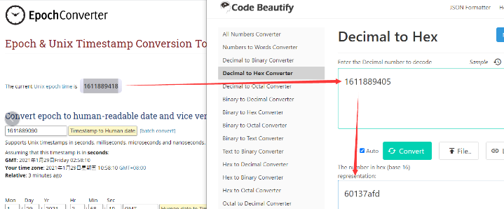
So, you can use downlink 3060137afd00 to set the current time 2021 – Jan -- 29 Friday 03:03:25
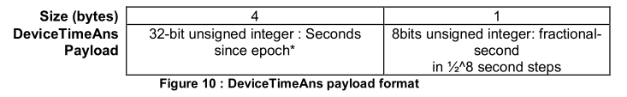
2.5.3 Set Device Time
You need to run downlink command 28 01 to enable time synchronization.
Once the LC01 joins the LoRaWAN network, it will send the MAC command DeviceTimeReq, and the server will reply with DeviceTimeAns to provide the current time to the LC01. If the LC01 fails to receive the time from the server, it will use its internal time and wait for the next time request. (By default, this occurs once every 10 days.)
Downlink Command: 0x28
- Example: 0x28 01 // Automatic time synchronization Enabled
- Example: 0x28 00 // Automatic time synchronization Disable.
2.5.4 Datalog Uplink payload (FPort=3)
The Datalog uplinks will use the following payload format.
Size(bytes) | 4 | 1 | 1 | 1 |
|---|---|---|---|---|
| Value | Unix Timestamp | Event | RelayStatus | DatalogReply |
No ACK Message: 1: This message means this payload is from Uplink Message which doesn't get ACK from the server before (for Automatically send None-ACK feature)
DatalogReply: 1: This message is a poll message reply.
- Poll Message Flag is set to 1.
- Each data entry is 7 bytes, to save airtime and battery, devices will send max bytes according to the current DR and Frequency bands.
For example, in US915 band, the max payload for different DR is:
a) DR0: max is 11 bytes so one entry of data
b) DR1: max is 53 bytes so devices will upload 4 entries of data (total 44 bytes)
c) DR2: total payload includes 11 entries of data
d) DR3: total payload includes 22 entries of data.
If devise doesn't have any data in the polling time. Device will uplink 7 bytes of 0
Example:
If user sends below downlink command: 31681D4580681D6FB005
Where : Start time: 681D4580 = time 25/5/9 08:00:00
Stop time: 681D6FB0 = time 25/5/9 11:00:00
LC01 will uplink this payload.

68 1E A7 AF 03 00 40 68 1E A8 C3 03 00 40 68 1E A8 FF 03 00 40 68 1E A9 3E 03 00 40 68 1E A9 5C 03 00 40 68 1E A9 7A 03 00 40 68 1E A9 98 03 00 40 68 1E A9 B6 03 00 40
Where the first 8 bytes is for the first entry:
68 1E A7 AF 03 00 40
Unix time is 0x68 1E A7 AF = 1746839471s=25/5/10 09:11:00 (GMT+8)
Event = 0x03 = HEARTBEAT_EVNET
RelayStatus = 0x00 = Relay closed
DatalogReply = 0x40 = Represents the current data as polled data
2.6 Frequency Plans
The LC01 uses OTAA mode and uses the below frequency plans by default (please visit the link below). Each frequency band uses different firmware. You should update the firmware to the corresponding band for your country.
http://wiki.dragino.com/xwiki/bin/view/Main/End%20Device%20Frequency%20Band/
2.7 Firmware Change Log
The firmware can be downloaded from this link: Dropbox--firmware
3. Configure LC01
3.1 Configure Methods
LC01 supports the following configure method:
- LoRaWAN Downlink: Instruction for different platforms: See IoT LoRaWAN Server section.
3.2 General Commands
The general commands are used to configure:
- General system settings like uplink interval.
- LoRaWAN protocol and radio related commands.
These commands are common for all Dragino Devices which support DLWS-005 LoRaWAN Stack. These commands can be found on the wiki:
http://wiki.dragino.com/xwiki/bin/view/Main/End%20Device%20AT%20Commands%20and%20Downlink%20Command/
3.3 Commands special design for LC01
These commands only valid for LC01, as below:
3.3.1 Set Transmit Interval Time
AT Command:
There is no AT command to set TDC time.
Feature: Change LoRaWAN End Node Transmit Interval.
Downlink Command: 0x01
Format: Command Code (0x01) followed by 3 bytes time value.
If the downlink payload is 0100003C, it means set the end node's transmit Interval is set to 0x00003C = 60 seconds, with the type code 01.
- Example 1: Downlink Payload: 0100001E // Sets the transmit interval (TDC) to 30 seconds
- Example 2: Downlink Payload: 0100003C // Sets the transmit interval (TDC) to 60 seconds
3.3.2 Get Device Status
Send a LoRaWAN downlink to request the device's alarm settings.
Downlink Payload: 0x26 01
The sensor will upload device status via FPort=5. See the payload section for details.
3.3.3 Clear Flash Record
AT Command:
There is no AT command to enable or disable the relay.
Feature: Clear flash storage for the data log feature.
Downlink Command: 0x08
- Example: 0x0801 // Clears all saved data in flash.
3.3.4 Relay enable or disable
AT Command:
There is no AT Command to control the Relay output.
Feature: Controls turning appliances on or off through the socket.
Downlink Command: 0x06
- Example: 0x06 01 // Relay enabled.
- Exampie: 0x06 00 // Relay disable.
3.3.5 Relay -- Control Relay Output time
Feature: Controls the relay output duration.
AT Command:
There is no AT Command to control the Relay output
Downlink Payload (prefix 0x09):
0x09 aa bb cc dd ee ff // Sets relay with time control
This command controls the relay output duration and includes 4 bytes:
First byte : Type code (0x09)
Second byte (aa): Inverter mode
01: Relay returns to its original state after the timeout
00: Relay switches to the inverse state after the timeout
Third byte (bb): Control method and port status:

Fourth/Fifth/Sixth/Seventh bytes (cc dd ee ff): Latching time (minimum: 6 seconds, unit: seconds)
The device will send an uplink packet if the downlink command is executed successfully.
Example payload:
1. 09 01 01 00 00 00 06
The relay will be set to NC, remain for 6 seconds, and then revert to its original state.
2. 09 01 00 00 00 00 06
The relay will change to NC, remain for 6 seconds, and then change to NO.
3. 09 00 01 00 00 00 06
Relay 1 will change to NO, remain for 6 seconds, and then change to NC.
4. 09 01 01 00 00 00 06
The relay will change to NO, remain for 6 seconds, and then revert to its original state.
3.3.6 Confirmed Mode
AT Command:
There is no AT command to control whether Confirmed Mode is enabled or disabled.
Feature: Mode for sending data that requires acknowledgment.
Downlink Command: 0x07
- Example: 0x07 01 // Confirmed Mode enabled.
- Example: 0x07 00 // Confirmed Mode disable.
3.3.7 Set the time synchronization interval
Feature: Set how often to perform time synchronization (default: 10 days, unit: days)
Downlink Command: 0x28
- Example: 0x28 01 // Synchronize once a day
- Example: 0x28 03 // Synchronize once every three days
4. OTA Firmware update
You can update the firmware on LC01 to:
- Change the frequency band/region.
- Add new features.
- Fix bugs.
The firmware and changelog can be downloaded from : Firmware download link
Methods to Update Firmware:
- (Recommended ) OTA firmware update via wireless : http://wiki.dragino.com/xwiki/bin/view/Main/Firmware%20OTA%20Update%20for%20Sensors/
5. FAQ
This will be added later.
6. Order Info
Part Number: LC01-XX
XX: The default frequency band
- AS923: LoRaWAN AS923 band
- AU915: LoRaWAN AU915 band
- EU433: LoRaWAN EU433 band
- EU868: LoRaWAN EU868 band
- KR920: LoRaWAN KR920 band
- US915: LoRaWAN US915 band
- IN865: LoRaWAN IN865 band
- CN470: LoRaWAN CN470 band
7. Packing Info
Package Includes:
- LC01 LoRaWAN Relay
Dimension and weight:
- Device Size: cm
- Device Weight: g
- Package Size / pcs : cm
- Weight / pcs : g
8. Support
- Support is provided Monday to Friday, from 09:00 to 18:00 GMT+8. Due to time zone differences, we cannot offer live support. However, your questions will be answered as soon as possible within the mentioned schedule.
- Please provide as much information as possible regarding your inquiry (e.g., product model, a clear description of the issue, and steps to reproduce it), and send an email to Support@dragino.cc.