How to connect 3rd party sensor to Dragino Wireless End Node
Table of Contents:
- 1. RS485-LB connects to third-party sensors
- 2. SN50v3-LB connects to third-party sensors
- 2.1 Working Modes & Sensor Data. Uplink via FPORT=2
- 2.1.1 MOD=1 (Default Mode)
- 2.1.2 MOD=2 (Distance Mode)
- 2.1.3 MOD=3 (3 ADC + I2C)
- 2.1.4 MOD=4 (3 x DS18B20)
- 2.1.5 MOD=5 (Weight Measurement by HX711)
- 2.1.6 MOD=6 (Counting Mode)
- 2.1.7 MOD=7 (Three interrupt contact modes)
- 2.1.8 MOD=8 (3ADC+1DS18B20)
- 2.1.9 MOD=9 (3DS18B20+ two Interrupt count mode)
- 2.1.10 MOD=10 (PWM input capture and output mode,Since firmware v1.2)
- 2.1.11 MOD=11 (TEMP117)
- 2.1.12 MOD=12 (Count+SHT31)
- 2.2 Decode payload
- 2.2.1 Battery Info
- 2.2.2 Temperature (DS18B20)
- 2.2.3 Digital Input
- 2.2.4 Analogue Digital Converter (ADC)
- 2.2.5 Digital Interrupt
- 2.2.6 I2C Interface (SHT20 & SHT31)
- 2.2.7 Distance Reading
- 2.2.8 Ultrasonic Sensor
- 2.2.9 Battery Output - BAT pin
- 2.2.10 +5V Output
- 2.2.11 BH1750 Illumination Sensor
- 2.2.12 PWM MOD
- 2.2.13 Working MOD
- 2.1 Working Modes & Sensor Data. Uplink via FPORT=2
- 3. PS-LB-NA connects to third-party sensors
- 4. Differences between three different motherboards
1. RS485-LB connects to third-party sensors
1.1 How to connect RS485-LB node to UART distance sensor?
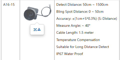
Take the A16-15 as an example, but the same setup can support different distance sensors, compare specifications see this link to DDS04-LB.
Connection:

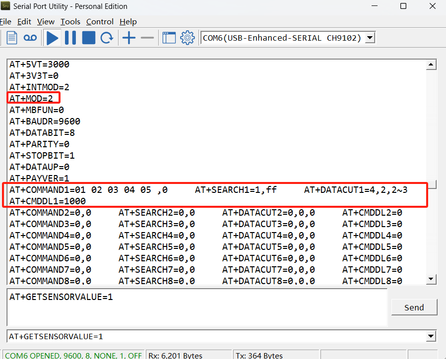
- AT command configuration:
AT+MOD=2
AT+COMMAND1=01 02 03 04 05 ,0 AT+SEARCH1=1,ff AT+DATACUT1=4,2,2~3 AT+CMDDL1=1000
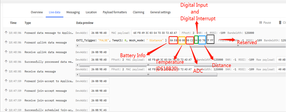
- Decoder: Decoding refer to this link.
- Example in TTN:

2. SN50v3-LB connects to third-party sensors
2.1 Working Modes & Sensor Data. Uplink via FPORT=2
SN50v3-LB/LS has different working mode for the connections of different type of sensors. This section describes these modes. Use can use the AT Command AT+MOD to set SN50v3-LB/LS to different working modes.
For example:
AT+MOD=2 // will set the SN50v3 to work in MOD=2 distance mode which target to measure distance via Ultrasonic Sensor.
Important Notice:
1. Some working modes has payload more than 12 bytes, The US915/AU915/AS923 frequency bands' definition has maximum 11 bytes in DR0. Server sides will see NULL payload while SN50v3-LB/LS transmit in DR0 with 12 bytes payload.
2. All modes share the same Payload Explanation from HERE.
3. By default, the device will send an uplink message every 20 minutes.
2.1.1 MOD=1 (Default Mode)
In this mode, uplink payload includes in total 11 bytes. Uplink packets use FPORT=2.
| Size(bytes) | 2 | 2 | 2 | 1 | 2 | 2 |
| Value | Bat | Temperature(DS18B20)(PC13) | ADC(PA4) | Digital in(PB15)&Digital Interrupt(PA8) | Temperature(SHT20 or SHT31 or BH1750 Illumination Sensor) | Humidity(SHT20 or SHT31) |

2.1.2 MOD=2 (Distance Mode)
This mode is target to measure the distance. The payload of this mode is totally 11 bytes. The 8th and 9th bytes is for the distance.
| Size(bytes) | 2 | 2 | 2 | 1 | 2 | 2 |
| Value | BAT | Temperature(DS18B20)(PC13) | ADC(PA4) | Digital in(PB15) & Digital Interrupt(PA8) | Distance measure by: 1) LIDAR-Lite V3HP | Reserved |
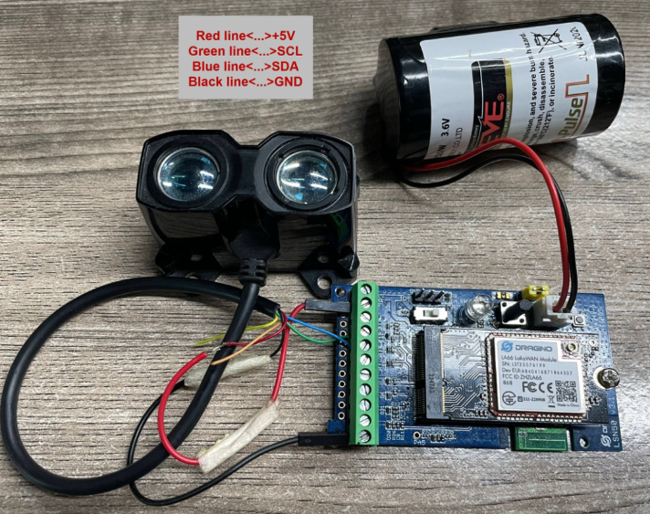
Connection of LIDAR-Lite V3HP:
Connection to Ultrasonic Sensor:
Need to remove R1 and R2 resistors to get low power,otherwise there will be 240uA standby current.
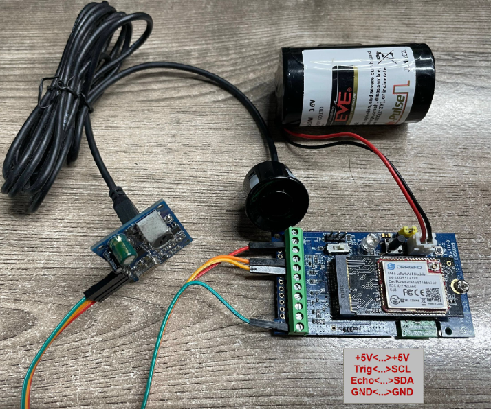
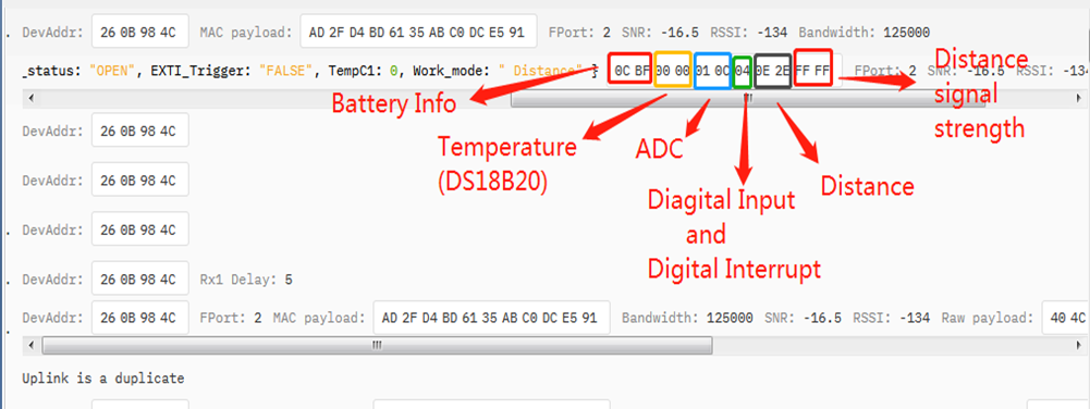
For the connection to TF-Mini or TF-Luna , MOD2 payload is as below:
| Size(bytes) | 2 | 2 | 1 | 2 | 2 | 2 |
| Value | BAT | Temperature(DS18B20)(PC13) | Digital in(PB15) & Digital Interrupt(PA8) | ADC(PA4) | Distance measure by:1)TF-Mini plus LiDAR | Distance signal strength |
Connection to TF-Mini plus LiDAR(UART version):
Need to remove R3 and R4 resistors to get low power,otherwise there will be 400uA standby current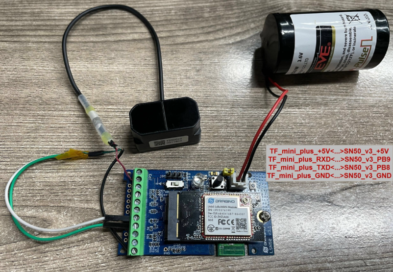
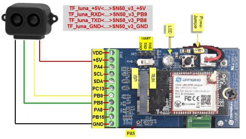
Connection to TF-Luna LiDAR (UART version):
Need to remove R3 and R4 resistors to get low power,otherwise there will be 400uA standby current
2.1.3 MOD=3 (3 ADC + I2C)
This mode has total 12 bytes. Include 3 x ADC + 1x I2C
Size(bytes) | 2 | 2 | 2 | 1 | 2 | 2 | 1 |
|---|---|---|---|---|---|---|---|
| Value | ADC1(PA4) | ADC2(PA5) | ADC3(PA8) | Digital Interrupt(PB15) | Temperature(SHT20 or SHT31 or BH1750 Illumination Sensor) | Humidity(SHT20 or SHT31) | Bat |
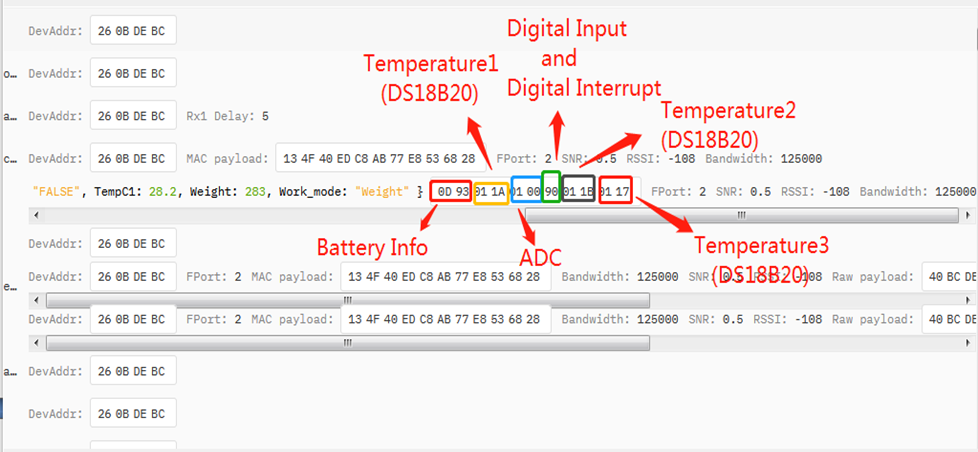
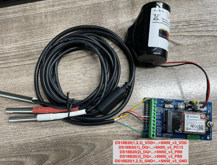
2.1.4 MOD=4 (3 x DS18B20)
This mode has total 11 bytes. As shown below:
| Size(bytes) | 2 | 2 | 2 | 1 | 2 | 2 |
| Value | BAT | Temperature1(DS18B20)(PC13) | ADC(PA4) | Digital in(PB15) & Digital Interrupt(PA8) | Temperature2(DS18B20) (PB9) | Temperature3(DS18B20)(PB8) |
2.1.5 MOD=5 (Weight Measurement by HX711)
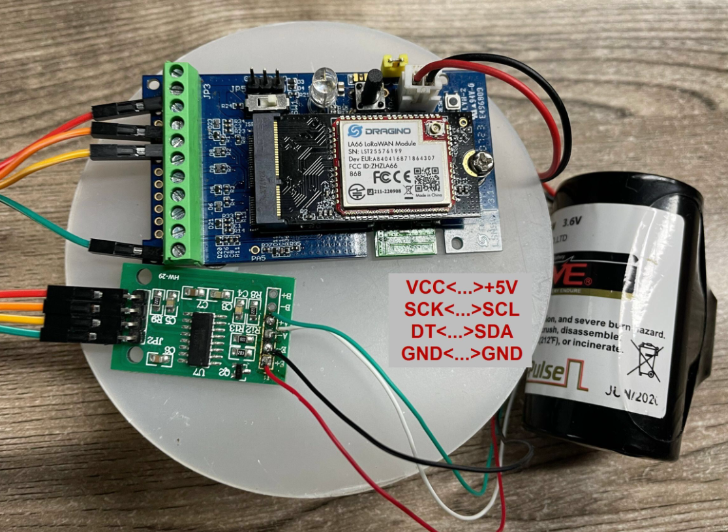
Each HX711 need to be calibrated before used. User need to do below two steps:
- Zero calibration. Don't put anything on load cell and run AT+WEIGRE to calibrate to Zero gram.
- Adjust calibration factor (default value 400): Put a known weight thing on load cell and run AT+WEIGAP to adjust the Calibration Factor.
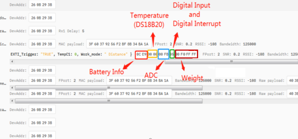
Weight has 4 bytes, the unit is g.
For example:
AT+GETSENSORVALUE =0
Response: Weight is 401 g
Check the response of this command and adjust the value to match the real value for thing.
Size(bytes) | 2 | 2 | 2 | 1 | 4 |
|---|---|---|---|---|---|
| Value | BAT | Temperature(DS18B20)(PC13) | ADC(PA4) | Digital in(PB15) & Digital Interrupt(PA8) | Weight |
2.1.6 MOD=6 (Counting Mode)
In this mode, the device will work in counting mode. It counts the interrupt on the interrupt pins and sends the count on TDC time.
Connection is as below. The PIR sensor is a count sensor, it will generate interrupt when people come close or go away. User can replace the PIR sensor with other counting sensors.
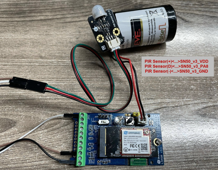
Note: LoRaWAN wireless transmission will infect the PIR sensor. Which cause the counting value increase +1 for every uplink. User can change PIR sensor or put sensor away of the SN50_v3 to avoid this happen.
| Size(bytes) | 2 | 2 | 2 | 1 | 4 |
|---|---|---|---|---|---|
| Value | BAT | Temperature(DS18B20)(PC13) | ADC(PA4) | Digital in(PB15) | Count(PA8) |

2.1.7 MOD=7 (Three interrupt contact modes)
Size(bytes) | 2 | 2 | 2 | 1 | 1 | 1 | 2 |
|---|---|---|---|---|---|---|---|
| Value | BAT | Temperature(DS18B20) | ADC(PA5) | Digital Interrupt1(PA8) | Digital Interrupt2(PA4) | Digital Interrupt3(PB15) | Reserved |

2.1.8 MOD=8 (3ADC+1DS18B20)
Size(bytes) | 2 | 2 | 2 | 1 | 2 | 2 |
|---|---|---|---|---|---|---|
| Value | BAT | Temperature(DS18B20) | ADC1(PA4) | Digital Interrupt(PB15) | ADC2(PA5) | ADC3(PA8) |
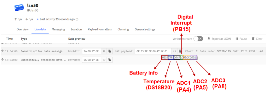
2.1.9 MOD=9 (3DS18B20+ two Interrupt count mode)
Size(bytes) | 2 | 2 | 2 | 1 | 2 | 4 | 4 |
|---|---|---|---|---|---|---|---|
| Value | BAT | Temperature | Temperature2 | Digital Interrupt | Temperature3 | Count1(PA8) | Count2(PA4) |
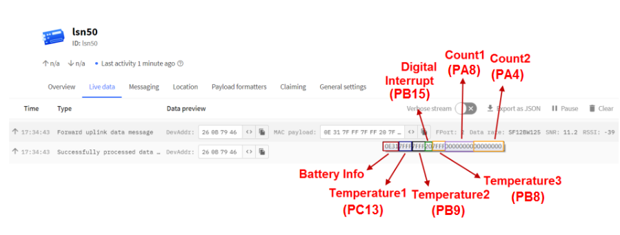
The newly added AT command is issued correspondingly:
AT+INTMOD1 PA8 pin: Corresponding downlink: 06 00 00 xx
AT+INTMOD2 PA4 pin: Corresponding downlink: 06 00 01 xx
AT+INTMOD3 PB15 pin: Corresponding downlink: 06 00 02 xx
AT+SETCNT=aa,bb
When AA is 1, set the count of PA8 pin to BB Corresponding downlink:09 01 bb bb bb bb
When AA is 2, set the count of PA4 pin to BB Corresponding downlink:09 02 bb bb bb bb
2.1.10 MOD=10 (PWM input capture and output mode,Since firmware v1.2)
Note: Firmware not release, contact Dragino for testing.
In this mode, the uplink can perform PWM input capture, and the downlink can perform PWM output.
It should be noted when using PWM mode.
2.1.10.1 Uplink, PWM input capture
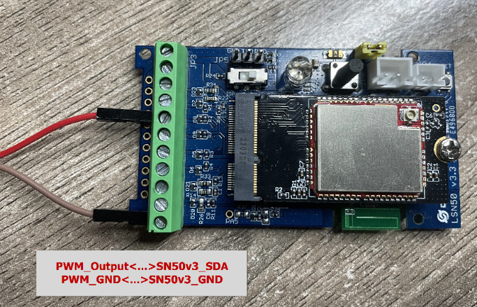
| Size(bytes) | 2 | 2 | 2 | 1 | 2 | 2 |
| Value | Bat | Temperature(DS18B20)(PC13) | ADC(PA4) | PWM_Setting | Pulse period | Duration of high level |

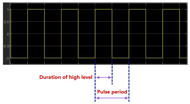
When the device detects the following PWM signal ,decoder will converts the pulse period and high-level duration to frequency and duty cycle.
Frequency:
If AT+PWMSET=0, Frequency= 1000000/Pulse period(HZ);
If AT+PWMSET=1, Frequency= 1000/Pulse period(HZ);
Duty cycle:
Duty cycle= Duration of high level/ Pulse period*100 (%).
2.1.10.2 Uplink, PWM output

AT+PWMOUT=a,b,c
a is the time delay of the output, the unit is ms.
b is the output frequency, the unit is HZ.
c is the duty cycle of the output, the unit is %.
Downlink: 0B 01 bb cc aa
aa is the time delay of the output, the unit is ms.
bb is the output frequency, the unit is HZ.
cc is the duty cycle of the output, the unit is %.
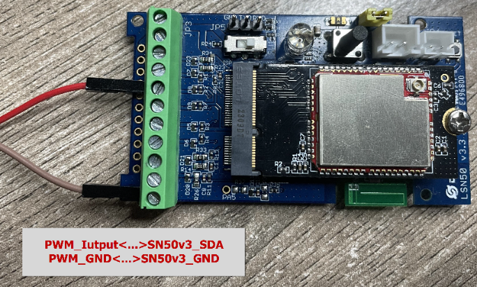
For example, send a AT command: AT+PWMOUT=65535,1000,50 The PWM is always out, the frequency is 1000HZ, and the duty cycle is 50.
The oscilloscope displays as follows:

2.1.10.3 Downlink, PWM output
Downlink: 0B xx xx xx yy zz zz
xx xx xx is the output frequency, the unit is HZ.
yy is the duty cycle of the output, the unit is %.
zz zz is the time delay of the output, the unit is ms.
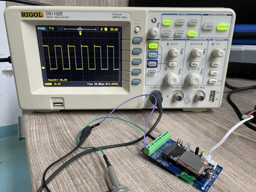
For example, send a downlink command: 0B 00 61 A8 32 13 88, the frequency is 25KHZ, the duty cycle is 50, and the output time is 5 seconds.
The oscilloscope displays as follows:
2.1.11 MOD=11 (TEMP117)
In this mode, uplink payload includes in total 11 bytes. Uplink packets use FPORT=2.
| Size(bytes) | 2 | 2 | 2 | 1 | 2 | 2 |
| Value | Bat | Temperature(DS18B20)(PC13) | ADC(PA4) | Digital in(PB15)&Digital Interrupt(PA8) | Temperature (TEMP117) | Reserved position, meaningless (0x0000) |

Connection:

2.1.12 MOD=12 (Count+SHT31)
This mode has total 11 bytes. As shown below:
| Size(bytes) | 2 | 2 | 2 | 1 | 4 |
|---|---|---|---|---|---|
| Value | BAT | Temperature_SHT31 | Humidity_SHT31 | Digital in(PB15) | Count(PA8) |

Wiring example:

2.2 Decode payload
While using TTN V3 network, you can add the payload format to decode the payload.
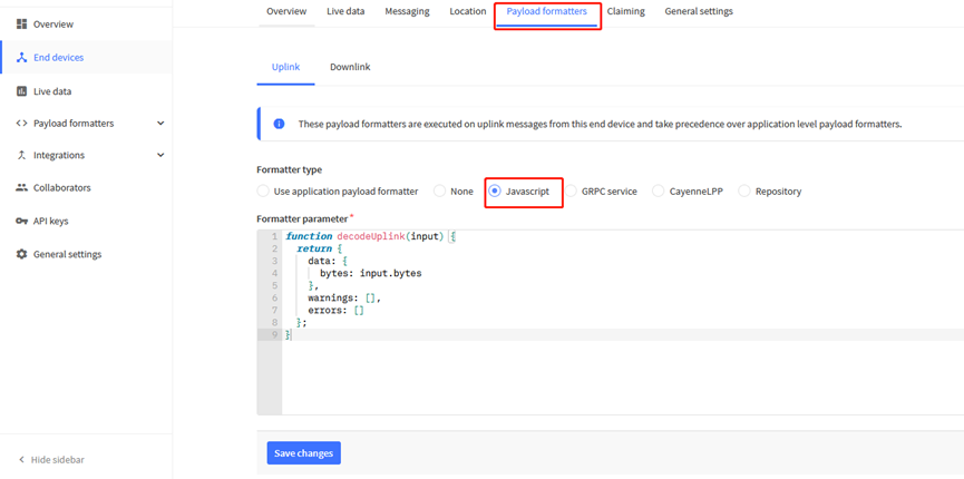
The payload decoder function for TTN V3 are here:
The payload decoder function for TTN V3 are here:
SN50v3-LB/LS TTN V3 Payload Decoder: https://github.com/dragino/dragino-end-node-decoder
2.2.1 Battery Info
Check the battery voltage for SN50v3-LB/LS.
Ex1: 0x0B45 = 2885mV
Ex2: 0x0B49 = 2889mV
2.2.2 Temperature (DS18B20)
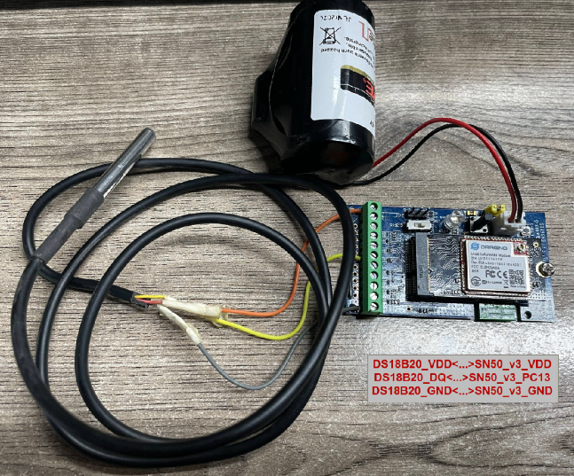
If there is a DS18B20 connected to PC13 pin. The temperature will be uploaded in the payload.
More DS18B20 can check the 3 DS18B20 mode
Connection:
Example:
If payload is: 0105H: (0105 & 8000 == 0), temp = 0105H /10 = 26.1 degree
If payload is: FF3FH : (FF3F & 8000 == 1) , temp = (FF3FH - 65536)/10 = -19.3 degrees.
(FF3F & 8000:Judge whether the highest bit is 1, when the highest bit is 1, it is negative)
2.2.3 Digital Input
The digital input for pin PB15,
- When PB15 is high, the bit 1 of payload byte 6 is 1.
- When PB15 is low, the bit 1 of payload byte 6 is 0.
When the digital interrupt pin is set to AT+INTMODx=0, this pin is used as a digital input pin.
Note: The maximum voltage input supports 3.6V.
2.2.4 Analogue Digital Converter (ADC)
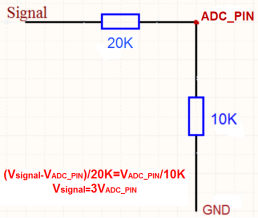
The measuring range of the ADC is only about 0.1V to 1.1V The voltage resolution is about 0.24mv.
When the measured output voltage of the sensor is not within the range of 0.1V and 1.1V, the output voltage terminal of the sensor shall be divided The example in the following figure is to reduce the output voltage of the sensor by three times If it is necessary to reduce more times, calculate according to the formula in the figure and connect the corresponding resistance in series.
Note: If the ADC type sensor needs to be powered by SN50_v3, it is recommended to use +5V to control its switch.Only sensors with low power consumption can be powered with VDD.
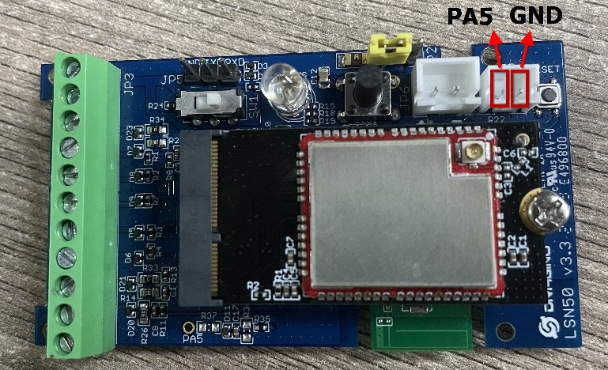
The position of PA5 on the hardware after LSN50 v3.3 is changed to the position shown in the figure below, and the collected voltage becomes one-sixth of the original.
2.2.5 Digital Interrupt
Digital Interrupt refers to pin PA8, and there are different trigger methods. When there is a trigger, the SN50v3-LB/LS will send a packet to the server.
Interrupt connection method:

Example to use with door sensor :
The door sensor is shown at right. It is a two wire magnetic contact switch used for detecting the open/close status of doors or windows.
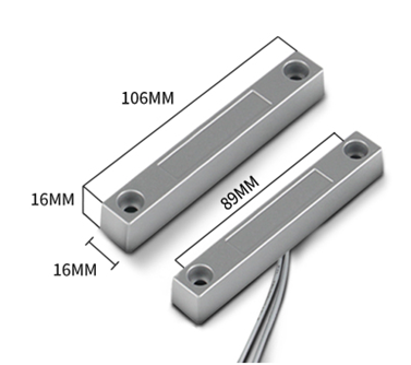
When the two pieces are close to each other, the 2 wire output will be short or open (depending on the type), while if the two pieces are away from each other, the 2 wire output will be the opposite status. So we can use SN50v3-LB/LS interrupt interface to detect the status for the door or window.
Below is the installation example:
Fix one piece of the magnetic sensor to the door and connect the two pins to SN50v3-LB/LS as follows:
One pin to SN50v3-LB/LS's PA8 pin
The other pin to SN50v3-LB/LS's VDD pin
Install the other piece to the door. Find a place where the two pieces will be close to each other when the door is closed. For this particular magnetic sensor, when the door is closed, the output will be short, and PA8 will be at the VCC voltage.
Door sensors have two types: NC (Normal close) and NO (normal open). The connection for both type sensors are the same. But the decoding for payload are reverse, user need to modify this in the IoT Server decoder.
When door sensor is shorted, there will extra power consumption in the circuit, the extra current is 3v3/R14 = 3v3/1Mohm = 3uA which can be ignored.
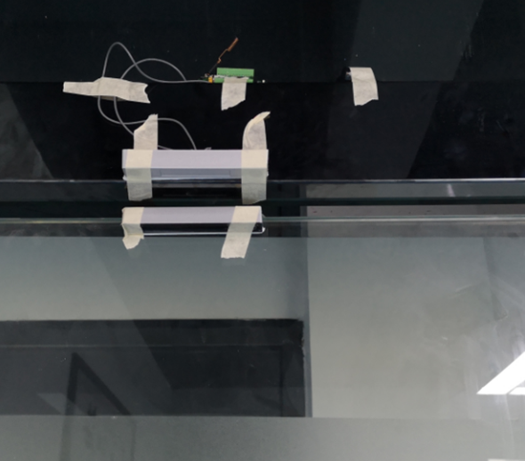
The above photos shows the two parts of the magnetic switch fitted to a door.
The software by default uses the falling edge on the signal line as an interrupt. We need to modify it to accept both the rising edge (0v --> VCC , door close) and the falling edge (VCC --> 0v , door open) as the interrupt.
The command is:
AT+INTMOD1=1 // (more info about INMOD please refer AT Command Manual. )
Below shows some screen captures in TTN V3:

In MOD=1, user can use byte 6 to see the status for door open or close. TTN V3 decoder is as below:
door= (bytes[6] & 0x80)? "CLOSE":"OPEN";
2.2.6 I2C Interface (SHT20 & SHT31)
The SDA and SCK are I2C interface lines. You can use these to connect to an I2C device and get the sensor data.
We have made an example to show how to use the I2C interface to connect to the SHT20/ SHT31 Temperature and Humidity Sensor.
Notice: Different I2C sensors have different I2C commands set and initiate process, if user want to use other I2C sensors, User need to re-write the source code to support those sensors. SHT20/ SHT31 code in SN50v3-LB/LS will be a good reference.
Below is the connection to SHT20/ SHT31. The connection is as below:
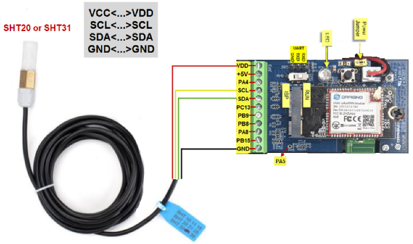
The device will be able to get the I2C sensor data now and upload to IoT Server.
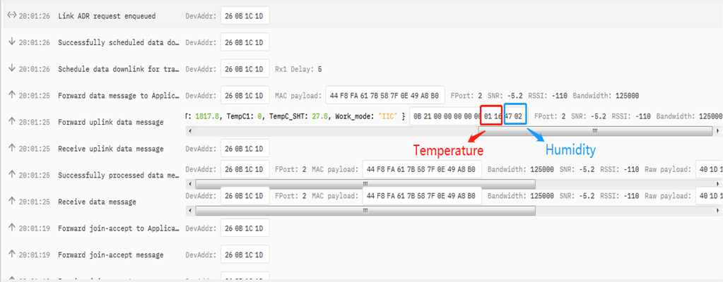
Convert the read byte to decimal and divide it by ten.
Example:
Temperature: Read:0116(H) = 278(D) Value: 278 /10=27.8℃;
Humidity: Read:0248(H)=584(D) Value: 584 / 10=58.4, So 58.4%
If you want to use other I2C device, please refer the SHT20 part source code as reference.
2.2.7 Distance Reading
Refer Ultrasonic Sensor section.
2.2.8 Ultrasonic Sensor
This Fundamental Principles of this sensor can be found at this link: https://wiki.dfrobot.com/Weather_-_proof_Ultrasonic_Sensor_with_Separate_Probe_SKU___SEN0208
The SN50v3-LB/LS detects the pulse width of the sensor and converts it to mm output. The accuracy will be within 1 centimeter. The usable range (the distance between the ultrasonic probe and the measured object) is between 24cm and 600cm.
The working principle of this sensor is similar to the HC-SR04 ultrasonic sensor.
The picture below shows the connection:

Connect to the SN50v3-LB/LS and run AT+MOD=2 to switch to ultrasonic mode (ULT).
The ultrasonic sensor uses the 8th and 9th byte for the measurement value.
Example:
Distance: Read: 0C2D(Hex) = 3117(D) Value: 3117 mm=311.7 cm
2.2.9 Battery Output - BAT pin
The BAT pin of SN50v3-LB/LS is connected to the Battery directly. If users want to use BAT pin to power an external sensor. User need to make sure the external sensor is of low power consumption. Because the BAT pin is always open. If the external sensor is of high power consumption. the battery of SN50v3-LB/LS will run out very soon.
2.2.10 +5V Output
SN50v3-LB/LS will enable +5V output before all sampling and disable the +5v after all sampling.
The 5V output time can be controlled by AT Command.
AT+5VT=1000
Means set 5V valid time to have 1000ms. So the real 5V output will actually have 1000ms + sampling time for other sensors.
By default the AT+5VT=500. If the external sensor which require 5v and require more time to get stable state, user can use this command to increase the power ON duration for this sensor.
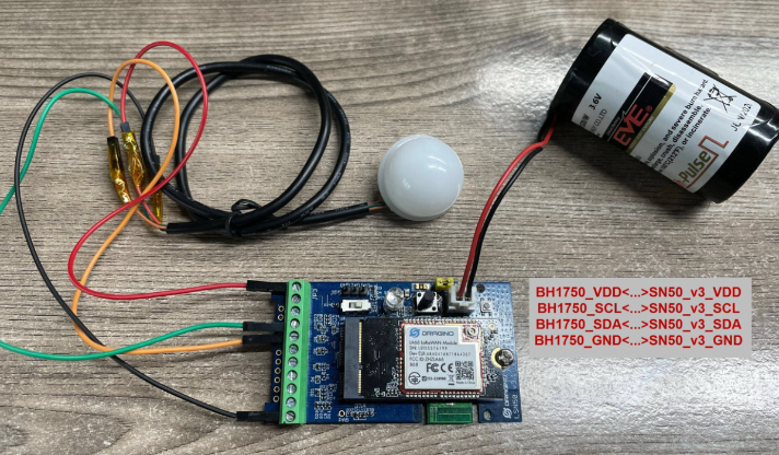
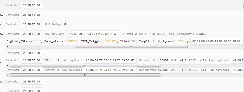
2.2.11 BH1750 Illumination Sensor
MOD=1 support this sensor. The sensor value is in the 8th and 9th bytes.
2.2.12 PWM MOD
The maximum voltage that the SDA pin of SN50v3 can withstand is 3.6V, and it cannot exceed this voltage value, otherwise the chip may be burned.
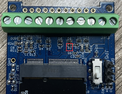
If the PWM pin connected to the SDA pin cannot maintain a high level when it is not working, you need to remove the resistor R2 or replace it with a resistor with a larger resistance, otherwise a sleep current of about 360uA will be generated. The position of the resistor is shown in the figure below:
The signal captured by the input should preferably be processed by hardware filtering and then connected in. The software processing method is to capture four values, discard the first captured value, and then take the middle value of the second, third, and fourth captured values.
Since the device can only detect a pulse period of 50ms when AT+PWMSET=0 (counting in microseconds), it is necessary to change the value of PWMSET according to the frequency of input capture.
PWM Input allows low power consumption. PWM Output to achieve real-time control, you need to go to class C. Power consumption will not be low.
For PWM Output Feature, there are two consideration to see if the device can be powered by battery or have to be powered by external DC.
a) If real-time control output is required, the SN50v3-LB/LS is already operating in class C and an external power supply must be used.
b) If the output duration is more than 30 seconds, better to use external power source.
2.2.13 Working MOD
The working MOD info is contained in the Digital in & Digital Interrupt byte (7th Byte).
User can use the 3rd ~ 7th bit of this byte to see the working mod:
Case 7th Byte >> 2 & 0x1f:
- 0: MOD1
- 1: MOD2
- 2: MOD3
- 3: MOD4
- 4: MOD5
- 5: MOD6
- 6: MOD7
- 7: MOD8
- 8: MOD9
- 9: MOD10
3. PS-LB-NA connects to third-party sensors
PS-LB-NA might connect to different kind of probes, 4~20mA represent the full scale of the measuring range. So a 12mA output means different meaning for different probe.
For example.
| Probe Type | 4~20mA scale for this probe | Example: 12mA actually meaning for this probe |
| PH Combination Electrodes | 0 ~ 14 pH | PH Value: 7 |
| Water Pressure Sensor | 0~5 meters | 2.5 meters pure water |
| Pressure transmitter probe | 0~1MPa | 0.5MPa air / gas or water pressure |
User can set different probe model for above probes. So IoT server is able to se identical how it should parse the 4~20mA or 0~30v sensor value and get the correct value.
3.1 0~20mA value (IDC_IN)
Payload Example:
27AE(H) = 10158 (D)/1000 = 10.158mA.

Connect to a 2 wire 4~20mA sensor.

3.2 0~30V value ( pin VDC_IN)
Measure the voltage value. The range is 0 to 30V.
Example:
138E(H) = 5006(D)/1000= 5.006V
3.3 IN1&IN2&INT pin
IN1 and IN2 are used as digital input pins.
Example:
09 (H): (0x09&0x08)>>3=1 IN1 pin is high level.
09 (H): (0x09&0x04)>>2=0 IN2 pin is low level.
This data field shows if this packet is generated by Interrupt Pin or not. Click here for the hardware and software set up. Note: The Internet Pin is a separate pin in the screw terminal.
Example:
09 (H): (0x09&0x02)>>1=1 The level of the interrupt pin.
09 (H): 0x09&0x01=1 0x00: Normal uplink packet.
0x01: Interrupt Uplink Packet.
3.4 Sensor value, FPORT=7
Size(bytes) | 2 | n |
| Value | BAT | Voltage value, each 2 bytes is a set of voltage values. |

Multiple sets of data collected are displayed in this form:
[voltage value1], [voltage value2], [voltage value3],…[voltage value n/2]
3.5 Decode payload in The Things Network
While using TTN network, you can add the payload format to decode the payload.

PS-LB-NA TTN Payload Decoder: https://github.com/dragino/dragino-end-node-decode
4. Differences between three different motherboards

