Table of Contents:
1. Introduction
1.1 What is NMDS200 NB-IoT Microwave Radar Distance Sensor
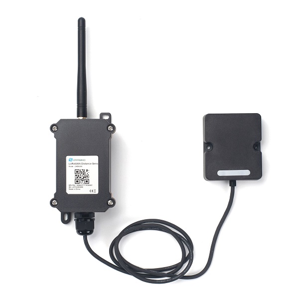
The Dragino NMDS200 is a NB-IoT Microwave Radar distance sensor. It uses 24Ghz Microwave to detect the distance between sensor and different objects. Compare vs ultrasonic or Lidar measurement method, Microwave Radar is more reliable for condensation / dusty environment. It can sense correct distance even there is water or thick dust on top of the sensor.
The NMDS200 can be applied to scenarios such as horizontal distance measurement, parking management system, object proximity and presence detection, intelligent trash can management system, robot obstacle avoidance, automatic control, sewer, etc.
NMDS200 can measure two distances: the closest object and next object behind the closest one.
NMDS200 supports Alarm Feature, user can set the NMDS200 to uplink data in a short interval when the distance is out of configured range.
NarrowBand-Internet of Things (NB-IoT) is a standards-based low power wide area (LPWA) technology developed to enable a wide range of new IoT devices and services. NB-IoT significantly improves the power consumption of user devices, system capacity, and spectrum efficiency, especially in deep coverage.
NMDS200 supports different uplink methods including TCP, MQTT, UDP, and CoAP for different application requirements.
NMDS200 is powered by 8500mAh Li-SOCI2 battery, It is designed for long-term use of up to 5 years. (Actually Battery life depends on the use environment, update period & uplink method)
To use NMDS200, user needs to check if there is NB-IoT coverage in the field and with the Nb-IoT bands that NMDS200 supports. If local operator support it, user needs to get a NB-IoT SIM card from the operator and install into NMDS200 to get NB-IoT network connection.
1.2 Features
- NB-IoT Bands: B1/B3/B8/B5/B20/B28 @H-FDD
- Short uplink interval for Distance Alarm
- Monitor Battery Level
- Microwave Radar for distance detection
- Datalog feature
- Uplink periodically
- Downlink to change configure
- Wall Mountable
- Outdoor Use
- Ultra-Low Power consumption
- AT Commands to change parameters
- Micro SIM card slot for NB-IoT SIM
- 8500mAh Battery for long-term use
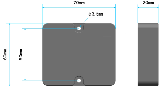
1.3 Radar probe specification
- Measuring Method: FMCW
- Frequency: 24.000 24.500 GHz
- Measurement output power: 6dBm
- Measure range: 0.5 20m
- Accuracy: ±0.1m
- Resolution: 0.01m
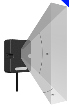
- Horizontal Angel: 78°
- Vertical Angel: 23°
1.4 Storage Temperature
-40°C to +85°C
1.5 Applications
- Horizontal distance measurement
- Liquid level measurement
- Parking management system
- Object proximity and presence detection
- Intelligent trash can management system
- Robot obstacle avoidance
- Automatic control
- Sewer
- Bottom water level monitoring
1.6 Specification
Common DC Characteristics:
- Supply Voltage: 2.1v ~ 3.6v
- Operating Temperature: 0 ~ 70°C
NB-IoT Spec:
- B1 @H-FDD: 2100MHz
- B3 @H-FDD: 1800MHz
- B8 @H-FDD: 900MHz
- B5 @H-FDD: 850MHz
- B20 @H-FDD: 800MHz
- B28 @H-FDD: 700MHz
1.7 Installation
Sensor measure direction and angle is as below. When install the sensor, please make sure the sensor direct to object.
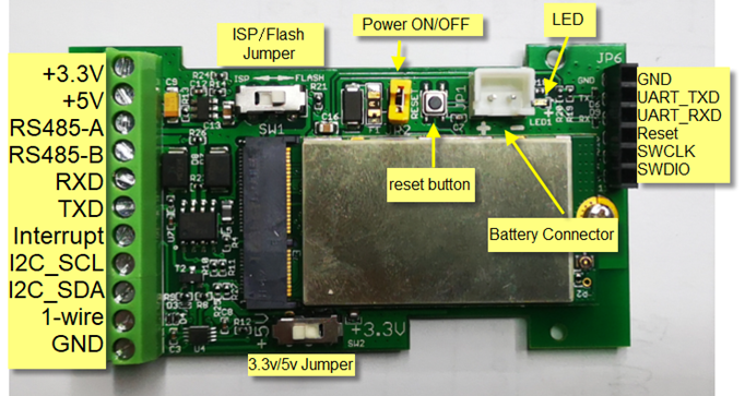
1.8 Pin Definitions and Switch
2. Use NMDS200 to communicate with IoT Server
2.1 How it works
The NB-IoT network will forward this value to IoT server via the protocol defined by NMDS200.
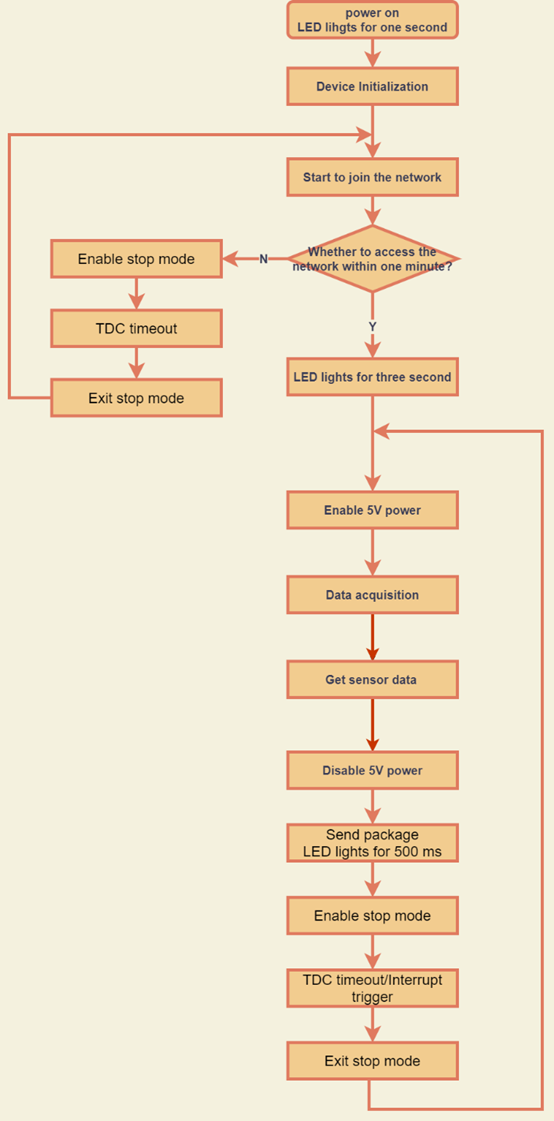
The diagram below shows the working flow in the default firmware of NMDS200:
2.2 Configure NMDS200
To use NMDS200 in your city, make sure to meet below requirements:
- Your local operator has already distributed an NB-IoT Network.
- The local NB-IoT network used the band that NMDS200 supports.
- Your operator is able to distribute the data received in their NB-IoT network to your IoT server.
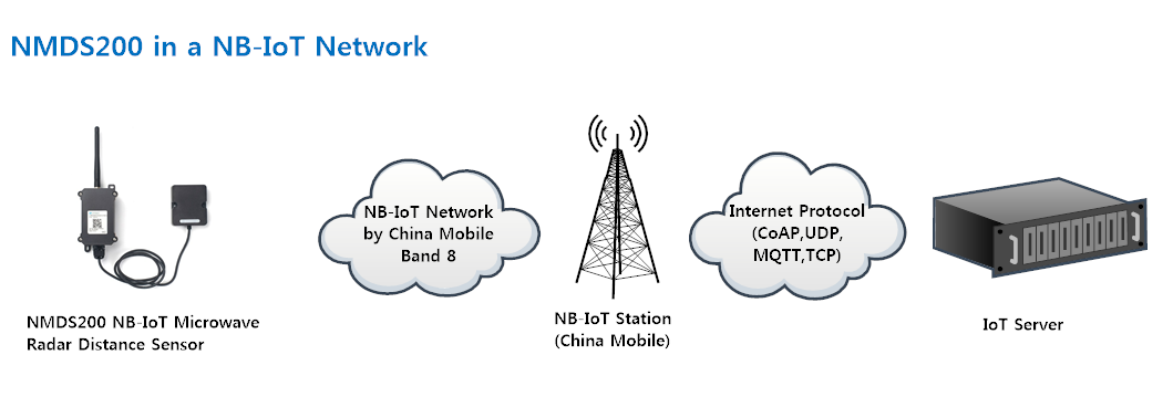
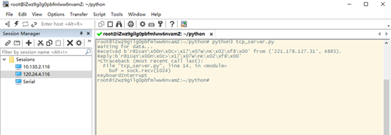
Below figure shows our testing structure. Here we have NB-IoT network coverage by China Mobile, the band they use is B8. The NMDS200 will use CoAP(120.24.4.116:5683) or raw UDP(120.24.4.116:5601) or MQTT(120.24.4.116:1883) or TCP(120.24.4.116:5600)protocol to send data to the test server.
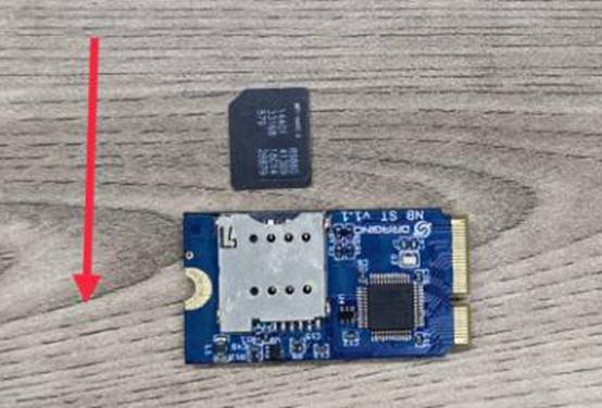
2.2.1 Insert NB-IoT SIM card
Insert the NB-IoT Card get from your provider.
User needs to take out the NB-IoT module and insert the SIM card like below:
2.2.2 Connect USB – TTL to NMDS200 and configure it
User need to configure NMDS200 via serial port to set the Server Address / Uplink Topic to define where and how-to uplink packets. NMDS200 support AT Commands, user can use a USB to TTL adapter to connect to NMDS200 and use AT Commands to configure it, as below.
Connection:
USB TTL GND <----> GND
USB TTL TXD <----> UART_RXD
USB TTL RXD <----> UART_TXD
In the PC, use below serial tool settings:
- Baud: 9600
- Data bits: 8
- Stop bits: 1
- Parity: None
- Flow Control: None
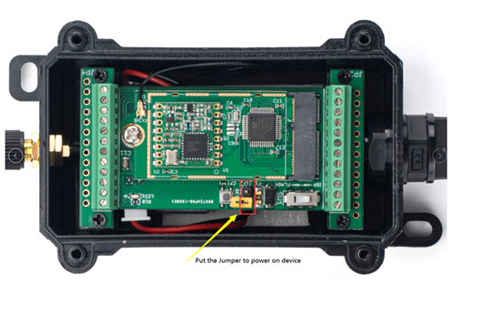
Make sure the switch is in FLASH position, then power on NMDS200 by connecting the Yellow Jumper.
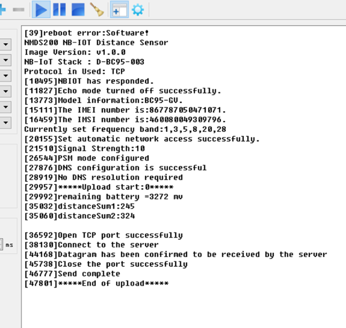
NMDS200 will output system info once powered on as below, we can enter the password: 12345678 to access AT Command input.
Note: the valid AT Commands can be found at: https://www.dropbox.com/sh/351dwor6joz8nwh/AADn1BQaAAxLF_QMyU8NkW47a?dl=0
2.2.3 Use CoAP protocol to uplink data
Note: if you don't have a CoAP server, you can refer this link to set up a CoAP server: http://wiki.dragino.com/xwiki/bin/view/Main/Set%20up%20CoAP%20Server/
Use below commands in NDS03A:
- AT+PRO=1 // Set to use CoAP protocol to uplink
- AT+SERVADDR=120.24.4.116,5683 // Set CoAP server address and port
- AT+URI=0,0,11,2,"mqtt" // Set CoAP resource path
For parameter description, please refer to AT command set
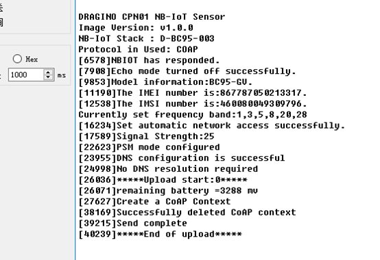
After configuring the server address and reset NMDS200 (via AT+ATZ ), NMDS200 will start to uplink sensor values to the CoAP server.

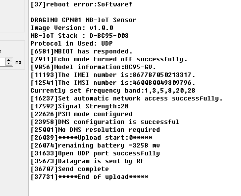
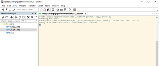
2.2.4 Use UDP protocol to uplink data(Default protocol)
AT Commands:
- AT+PRO=2 // Set to use UDP protocol to uplink
- AT+SERVADDR=120.24.4.116,5601 // Set UDP server address and port
- AT+CFM=1 // If the server does not respond, this command is unnecessary
2.2.5 Use MQTT protocol to uplink data
AT Commands:
- AT+PRO=3 // Set to use MQTT protocol to uplink
- AT+SERVADDR=120.24.4.116,1883 // Set MQTT server address and port
- AT+CLIENT=CLIENT // Set up the CLIENT of MQTT
- AT+UNAME=UNAME // Set the username of MQTT
- AT+PWD=PWD // Set the password of MQTT
- AT+PUBTOPIC=NSE01_PUB // Set the sending topic of MQTT
- AT+SUBTOPIC=NSE01_SUB // Set the subscription topic of MQTT
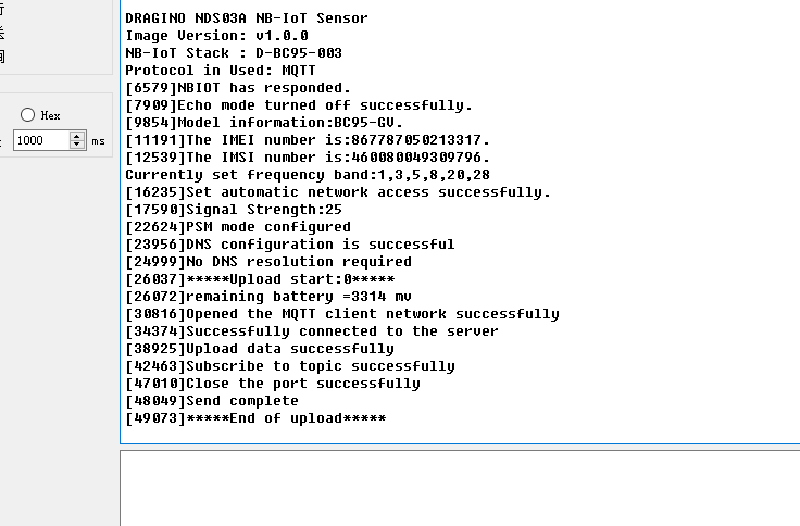
MQTT protocol has a much higher power consumption compare with UDP / CoAP protocol. Please check the power analyze document and adjust the uplink period to a suitable interval.
2.2.6 Use TCP protocol to uplink data
AT Commands:
- AT+PRO=4 // Set to use TCP protocol to uplink
- AT+SERVADDR=120.24.4.116,5600 // Set TCP server address and port
2.2.7 Change Update Interval
User can use below command to change the uplink interval.
- AT+TDC=7200 // Set Update Interval to 7200s (4 hours)
NOTE:
1. By default, the device will send an uplink message every 4 hour.
2.3 Uplink Payload
The uplink payload includes 26 bytes in total by default.
Each time the device uploads a data package. The user can use the AT+NOUD command to upload the recorded data.Up to 32 sets of recorded data can be uploaded.
When AT+TTRCHANNEL=1:
| Size(bytes) | 8 | 2 | 2 | 1 | 1 | 1 | 1 | 3 | 3 |
|---|---|---|---|---|---|---|---|---|---|
| Value | Device ID | Ver | BAT | Signal Strength | MOD | Door Status | Alarm Status | door open num(pb14) | last open time(pb14) |
| 4 | 1 | 3 | 3 | 4 | 1-32 group |
| Time stamp | Door Status(pb14) | door open num(pb14) | last open time(pb14) | Time stamp | ... |
When AT+TTRCHANNEL=2:
| Size(bytes) | 8 | 2 | 2 | 1 | 1 | 1 | 1 | 3 | 3 |
|---|---|---|---|---|---|---|---|---|---|
| Value | Device ID | Ver | BAT | Signal Strength | MOD | Door Status(pb14) | Alarm Status(pb14) | door open num(pb14) | last open time(pb14) |
| 1 | 1 | 3 | 3 | 4 | 1 | 3 |
| Door Status(pb15) | Alarm Status(pb15) | door open num(pb15) | last open time(pb15) | Time stamp | Door Status(pb14) | door open num(pb14) |
| 3 | 1 | 3 | 3 | 4 | 1-32 group |
| last open time(pb14) | Door Status(pb15) | door open num(pb15) | last open time(pb15) | Time stamp | ...... |
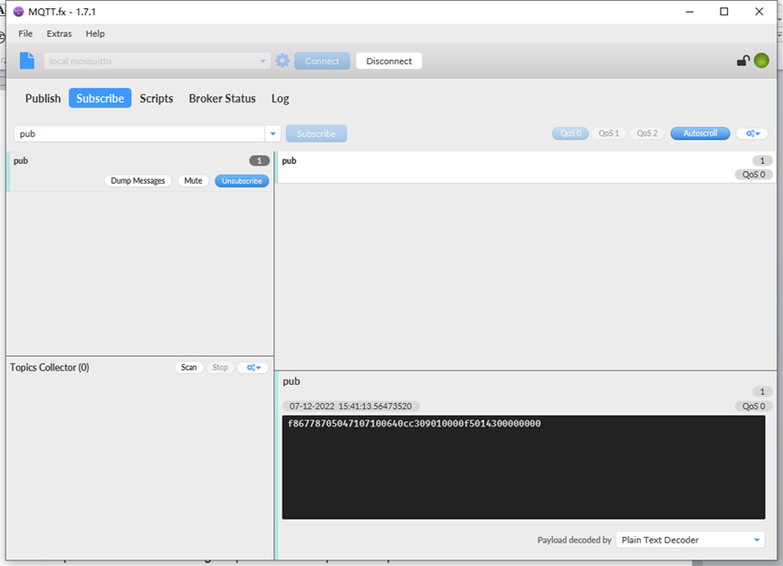
If we use the MQTT client to subscribe to this MQTT topic, we can see the following information when the NDS03A uplink data.
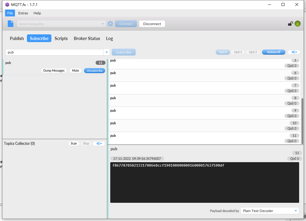
The payload is ASCII string, representative same HEX:
0x f867787050213317 0064 0ccf 19 01 00 00 000016 000017 637590df
where:
- Device ID: 0x f867787050213317 = f867787050213317
- Version: 0x0064=100=1.0.0
- BAT : 0x0ccf = 3279 mV = 3.279V
- Singal: 0x19 = 25
- Mod: 0x01 = 1
- Door Status: 0x00=0
- Alarm Status: 0x00 =0
- door open num: 0x000016 =22
- last open time: 0x000017 =23
- Timestamp: 0x637590df =1668649183 (Unix Time)
2.4 Payload Explanation and Sensor Interface
2.4.1 Device ID
By default, the Device ID is equal to the last 15 bits of IMEI.
User can use AT+DEUI to set Device ID
Example:
AT+DEUI=868411056754138
The Device ID is stored in a non-erase area, Upgrade the firmware or run AT+FDR won't erase the Device ID.
2.4.2 Version Info
Specify the software version: 0x64=100, which means firmware version 1.00.
For example 0x00 64 : This device is NDS03A 1 with firmware version 1.0.0.
2.4.3 Battery Info
Check the battery voltage for NDS03A.
Ex1: 0x0B45 = 2885mV
Ex2: 0x0B49 = 2889mV
2.4.4 Signal Strength
NB-IoT Network signal Strength.
Ex1: 0x1d = 29
0 -113dBm or less
1 -111dBm
2...30 -109dBm... -53dBm
31 -51dBm or greater
99 Not known or not detectable
2.4.5 Disalarm: (default: 0)
If Disalarm = 1, NDS03A will only send uplink at every TDC periodically. This is normally use for pulse meter application, in this application, there are many open/close event, and platform only care about the total number of pulse.
If Disalarm = 0, NDS03A will send uplink at every TDC periodically and send data on each open/close event. This is useful for the application user need to monitor the open/close event in real-time.
Note: When Disalarm=0, a high frequently open/close event will cause lots of uplink and drain battery very fast.
2.4.6 Keep Status & Keep Time
Shows the configure value of Alarm Base on Timeout Feature
2.4.7 Timestamp
Timestamp : 0x6315537b =1662342011
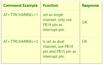
2.4.8 Switch Dual Channel Mode
NDS03A can connect two door sensors. Another door sensor can be connected to PB15 pin. Both channels support alarm function.
2.5 Downlink Payload
By default, NDS03A prints the downlink payload to console port.
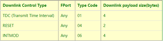
Examples:
- Set TDC
If the payload=0100003C, it means set the END Node's TDC to 0x00003C=60(S), while type code is 01.
Payload: 01 00 00 1E TDC=30S
Payload: 01 00 00 3C TDC=60S
- Reset
If payload = 0x04FF, it will reset the NDS03A
- INTMOD
Downlink Payload: 06000003, Set AT+INTMOD=3
2.6 LED Indicator
The NDS03A has an internal LED which is to show the status of different states.
- When the device starts normally, the LED will light up for 1 second.
- After NDS03A join NB-IoT network. The LED will be ON for 3 seconds.
- For each uplink probe, LED will be on for 500ms.
2.7 Alarm Base on Timeout
NDS03A can monitor the timeout for a status change, this feature can be used to monitor some events such as door opening too long etc. Related Parameters are:
1. Keep Status: Status to be monitor
Keep Status = 1: Monitor Close to Open event
Keep Status = 0: Monitor Open to Close event
2. Keep Time: Timeout to send an Alarm
Range 0 ~ 65535(0xFFFF) seconds.
If keep time = 0, Disable Alarm Base on Timeout feature.
If keep time > 0, device will monitor the keep status event and send an alarm when status doesn't change after timeout.
AT Command to configure:
PB14 PIN:
AT+TTRIG=1,30 --> When the Keep Status change from connected to disconnect, and device remains in disconnect status for more than 30 seconds. NDS03A will send an uplink packet, the Alarm bit (the second bit of 1st byte of payload) on this uplink packet is set to 1.
AT+TTRIG=0,0 --> Default Value, disable timeout Alarm.
PB15 PIN:
AT+TTRIG2=1,30
AT+TTRIG2=0,0
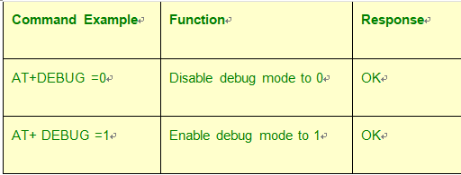
2.8 Set debug mode
Feature: Enable or Disable debug mode
AT Command: AT+DEBUG
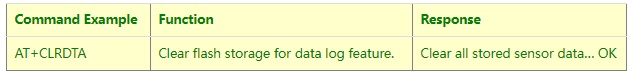
2.9 Clear Flash Record
Feature: Clear flash storage for data log feature.
AT Command: AT+CLRDTA
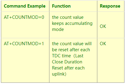
2.10 Count Mod
AT Command: AT+COUNTMOD
2.11 Interrupt Pin Channel Mod
AT Command: AT+TTRCHANNEL
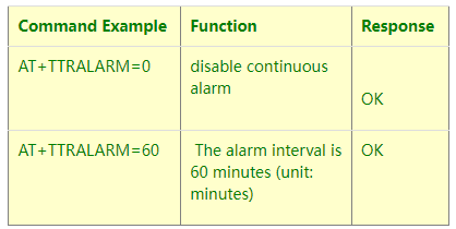
2.12 TTRIG1/2 timeout status alarm
It needs to be used with AT+TTRIG1 or AT+TTRIG2. When TTRIG1 or TTRIG2 times out and causes an alarm, and the status does not change subsequently, an alarm packet will be sent at the alarm interval.
AT Command: AT+TTRALARM
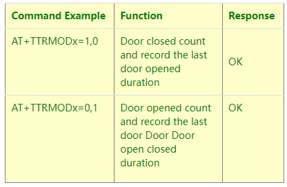
2.13 Select counting mode
AT Command: AT+TTRMODx=a,b
When a=0, the door is opened to count, and when a=1,the closed door is counted.
When b=0, it is the last door open duration, and when b=1,the last door close duration.
2.14 Set the number of data to be uploaded and the recording time
AT Command:
AT+TR=900 // The unit is seconds, and the default is to record data once every 900 seconds.( The minimum can be set to 180 seconds)
AT+NOUD=8 // The device uploads 0 sets of recorded data by default. Up to 32 sets of record data can be uploaded.
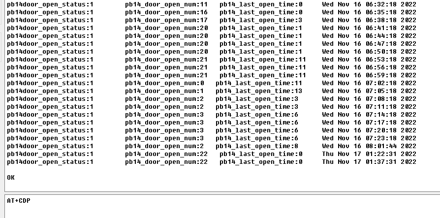
2.15 Read or Clear cached data
AT Command:
AT+CDP // Read cached data
AT+CDP=0 // Clear cached data
2.16 Firmware Change Log
Download URL & Firmware Change log: https://www.dropbox.com/sh/hacq385w6qgnonr/AAC3D79GFGF1JdZUIzNegn2Ha?dl=0
Upgrade Instruction: Upgrade Firmware
2.17 Battery Analysis
2.17.1 Battery Type
The NDS03A battery is a combination of an 8500mAh Li/SOCI2 Battery and a Super Capacitor. The battery is non-rechargeable battery type with a low discharge rate (<2% per year). This type of battery is commonly used in IoT devices such as water meter.
The battery is designed to last for several years depends on the actual use environment and update interval.
The battery-related documents as below:
2.17.2 Power consumption Analyze
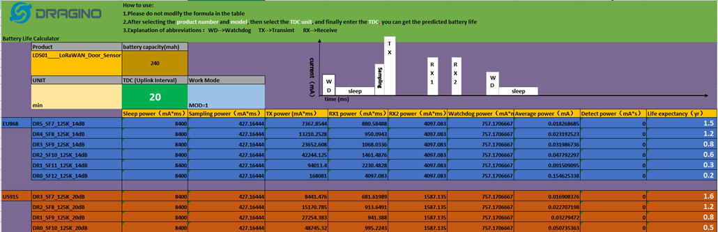
Dragino battery powered product are all runs in Low Power mode. We have an update battery calculator which base on the measurement of the real device. User can use this calculator to check the battery life and calculate the battery life if want to use different transmit interval.
Instruction to use as below:
Step 1: Downlink the up-to-date DRAGINO_Battery_Life_Prediction_Table.xlsx from: https://www.dragino.com/downloads/index.php?dir=LoRa_End_Node/Battery_Analyze/
Step 2: Open it and choose
- Product Model
- Uplink Interval
- Working Mode
And the Life expectation in difference case will be shown on the right.
2.17.3 Battery Note
The Li-SICO battery is designed for small current / long period application. It is not good to use a high current, short period transmit method. The recommended minimum period for use of this battery is 5 minutes. If you use a shorter period time to transmit LoRa, then the battery life may be decreased.
2.17.4 Replace the battery
The default battery pack of NDS03A includes a ER26500 plus super capacitor. If user can't find this pack locally, they can find ER26500 or equivalence without the SPC1520 capacitor, which will also work in most case. The SPC can enlarge the battery life for high frequency use (update period below 5 minutes).
3. Access NB-IoT Module
Users can directly access the AT command set of the NB-IoT module.
The AT Command set can refer the BC35-G NB-IoT Module AT Command: https://www.dragino.com/downloads/index.php?dir=datasheet/other_vendors/BC35-G/

4. Using the AT Commands
4.1 Access AT Commands
See this link for detail: https://www.dropbox.com/sh/351dwor6joz8nwh/AADn1BQaAAxLF_QMyU8NkW47a?dl=0
AT+<CMD>? : Help on <CMD>
AT+<CMD> : Run <CMD>
AT+<CMD>=<value> : Set the value
AT+<CMD>=? : Get the value
General Commands
AT : Attention
AT? : Short Help
ATZ : MCU Reset
AT+TDC : Application Data Transmission Interval
AT+CFG : Print all configurations
AT+CFGMOD : Working mode selection
AT+INTMOD : Set the trigger interrupt mode
AT+5VT : Set extend the time of 5V power
AT+PRO : Choose agreement
AT+RXDL : Extend the sending and receiving time
AT+SERVADDR : Server Address
AT+TR : Get or Set record time
AT+NOUD : Get or Set the number of data to be uploaded
AT+CDP : Read or Clear cached data
AT+ DEBUG : Enable or Disable debug mode
AT+ TTRIG1 : Get or Set PB14 PIN Alarm Base on Timeout
AT+ TTRIG2 : Get or Set PB15 PIN Alarm Base on Timeout
AT+COUNTMOD : Get or Set the count mode
AT+TTRCHANNEL : Get or Set the number of interrupt channels
AT+TTRALARM : Get or Set TTRIG1 of Alarm interval (unit: minute)
AT+DISALARM : Enable/Disable Alarm for door open/close or water leak event
AT+ CLRC : Clear current door open count
COAP Management
AT+URI : Resource parameters
UDP Management
AT+CFM : Upload confirmation mode (only valid for UDP)
MQTT Management
AT+CLIENT : Get or Set MQTT client
AT+UNAME : Get or Set MQTT Username
AT+PWD : Get or Set MQTT password
AT+PUBTOPIC : Get or Set MQTT publish topic
AT+SUBTOPIC : Get or Set MQTT subscription topic
Information
AT+FDR : Factory Data Reset
AT+PWORD : Serial Access Password
5. FAQ
5.1 How to Upgrade Firmware
User can upgrade the firmware for 1) bug fix, 2) new feature release.
Please see this link for how to upgrade: http://wiki.dragino.com/xwiki/bin/view/Main/Firmware%20Upgrade%20Instruction%20for%20STM32%20base%20products/#H2.HardwareUpgradeMethodSupportList
Notice: NDS03A and LDS03A share the same mother board. They use the same connection and method to update.
6. Trouble Shooting
6.1 Connection problem when uploading firmware
6.2 AT Command input doesn't work
In the case if user can see the console output but can't type input to the device. Please check if you already include the ENTER while sending out the command. Some serial tool doesn't send ENTER while press the send key, user need to add ENTER in their string.
7. Order Info
Part Number: NDS03A
8. Packing Info
Package Includes:
- NDS03A Open/Close Door Sensor x 1
9. Support
- Support is provided Monday to Friday, from 09:00 to 18:00 GMT+8. Due to different timezones we cannot offer live support. However, your questions will be answered as soon as possible in the before-mentioned schedule.
- Provide as much information as possible regarding your enquiry (product models, accurately describe your problem and steps to replicate it etc) and send a mail to support@dragino.com