
Contents:
1. Introduction
1.1 What is LDS03A Open/Close Door Sensor
The Dragino LDS03A is an Open/Close LoRaWAN Door Sensor. It detects door open/close status and uplinks to IoT server via LoRaWAN network. user can see the door status, open duration, open counts in the IoT Server.
LDS03A is powered by a 8500mAh Li-SOCI2 battery. It can be used for up to 10 years.
The LDS03A will send periodically data every 2 hours as well as for each door open/close action. It also counts the door open times and calculates the last door open duration. Users can also disable the uplink for each open/close event, instead, LDS03A can count each open event and uplink periodically.
LDS03A has a Datalog feature, it will record the open/close event and the user can retrieve the history from LoRaWAN.
LDS03A has the open alarm feature, user can set this feature so the device will send an alarm if the door has been open for a certain time.
LDS03A is designed for outdoor use. It has a weatherproof enclosure and industrial level battery to work in low to high temperatures.
Each LDS03A is pre-load with a set of unique keys for LoRaWAN registration, register these keys to LoRaWAN server and it will auto-connect after power on.
*Battery life depends on how often to send data, please see battery analyzer.
1.2 Features
- LoRaWAN v1.0.3 Class A protocol.
- Frequency Bands: CN470/EU433/KR920/US915/EU868/AS923/AU915/IN865/RU864
- Door Open/Close detect
- Door open/close statistics
- 8500mAh industrial battery(none-rechargeable)
- AT Commands to change parameters
- Uplink on periodically and open/close event
- Datalog feature
- Remote configure parameters via LoRa Downlink
- Firmware upgradable via program port
- Wall Mountable
- Outdoor Use
1.3 Storage & Operation Temperature
-40°C to +85°C
1.4 Applications

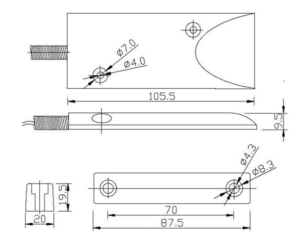
1.5 Mechanical
1.6 Pin Definitions and Switch
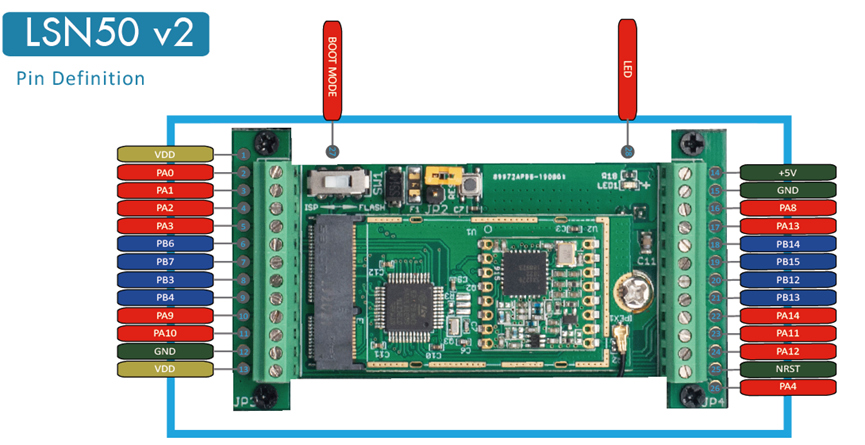
LDS03A is based on LSN50v2
1.6.1 Pin Definition
The device is pre-configured to connect to a door sensor. The other pins are not used. If user wants to know more about other pins, please refer to the user manual of LSN50v2 at: http://www.dragino.com/downloads/index.php?dir=LSN50-LoRaST/
1.6.2 Jumper JP2(Power ON/OFF)
Power on Device when putting this jumper.
1.6.3 BOOT MODE / SW1
1) ISP: upgrade mode, device won't have any signal in this mode. but ready for upgrade firmware. LED won't work. Firmware won’t run.
2) Flash: work mode, the device starts to work and send out console output for further debug
1.6.4 Reset Button
Press to reboot the device.
1.6.5 LED
It will flash:
- Boot the device in flash mode
- Send an uplink packet
2. Operation Mode
2.1 How it works
Each LDS03A is shipped with a worldwide unique set of OTAA keys. To use LDS03A in a LoRaWAN network, user needs to input the OTAA keys in the LoRaWAN network server. So LDS03A can join the LoRaWAN network and start to transmit sensor data.
2.2 Example to use for LoRaWAN network
This section shows an example of how to join the TTN V3 LoRaWAN IoT server. Usages with other LoRaWAN IoT servers are similar.
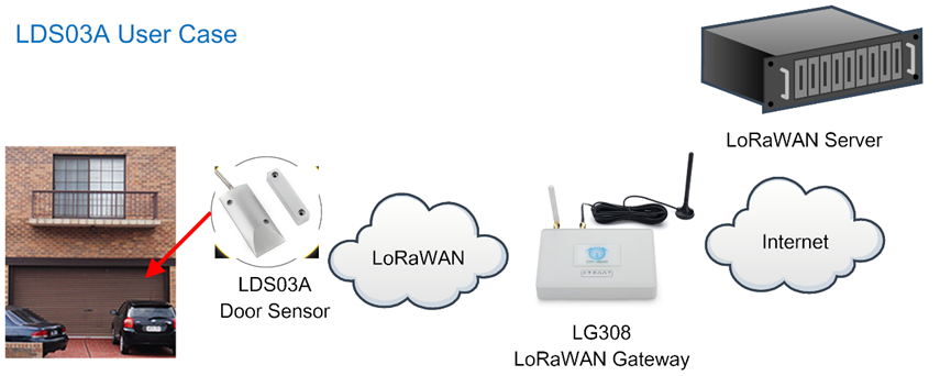
- In this user case, the LDS03A is installed on the door edge to detect the open/close event and send the status to the LoRaWAN server. The LDS03A will uplink different types of messages to the LoRaWAN server. See Uplink payload for detail.
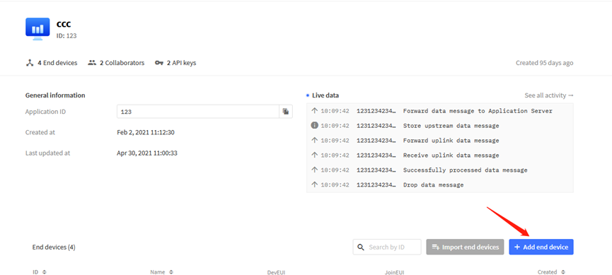
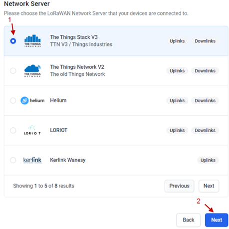
Assume the LG308 is already set to connect to the TTN V3 network . We need to add the LDS03A device in TTN V3:
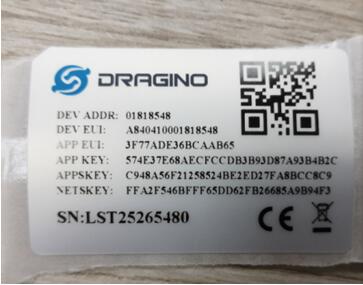
Step 1: Create a device in TTN V3 with the OTAA keys from LDS03A.
Each LDS03A is shipped with a sticker with the default device EUI as below:
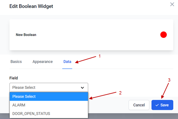
Users can enter these keys in the LoRaWAN Server portal. Below is the TTN V3 screenshot:
Add APP EUI in the application.
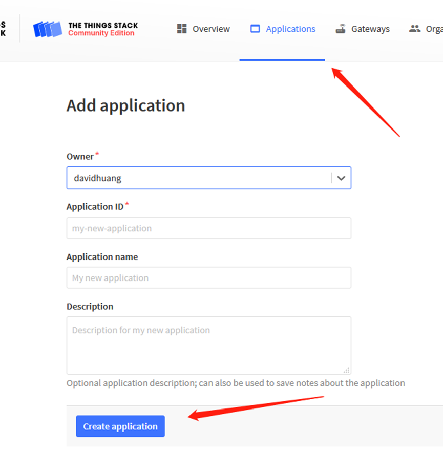
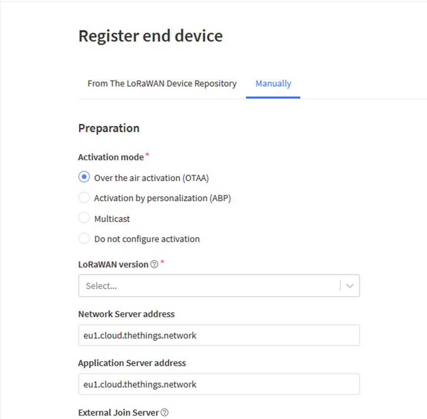
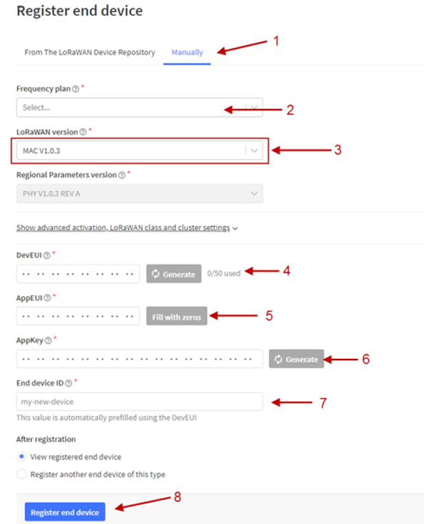
Add APP KEY and DEV EUI
Step 2: Power on LDS03A
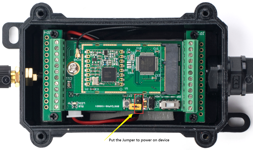
Put the jumper to power on LDS03A and it will auto-join to the TTN V3 network. After join success, it will start to upload sensor data to TTN V3 and the user can see it in the panel.

2.3 Uplink Payload
Uplink payloads have two types:
Open/Close Status: Use FPORT=2
Other control commands: Use other FPORT fields.
The application server should parse the correct value based on FPORT settings.
2.3.1 Device Status, FPORT=5
Include device configure status. Once LDS03A Joined the network, it will uplink this message to the server. After that, LDS03A will uplink Device Status every 12 hours.
Users can also use the downlink command(0x26 01) to ask LDS03A to resend this uplink. This uplink payload also includes the DeviceTimeReq to get time.
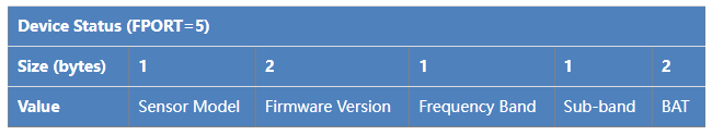
Example parse in TTNv3
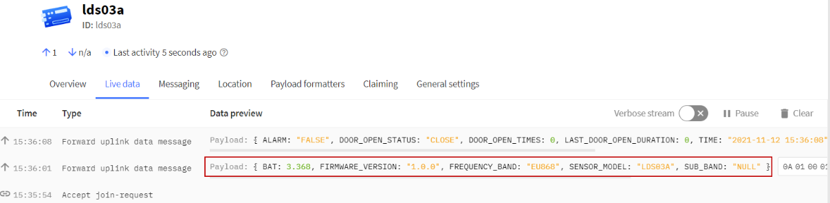
- Sensor Model: For LDS03A, this value is 0x0A
- Firmware Version: 0x0100, Means: v1.0.0 version
- Frequency Band:
*0x01: EU868
*0x02: US915
*0x03: IN865
*0x04: AU915
*0x05: KZ865
*0x06: RU864
*0x07: AS923
*0x08: AS923-1
*0x09: AS923-2
*0x0a: AS923-3
*0x0b: CN470
*0x0c: EU433
*0x0d: KR920
*0x0e: MA869
- Sub-Band:
- AU915 and US915:value 0x00 ~ 0x08
- CN470: value 0x0B ~ 0x0C
- Other Bands: Always 0x00
- Battery Info:
Check the battery voltage.
Ex1: 0x0B45 = 2885mV
Ex2: 0x0B49 = 2889mV
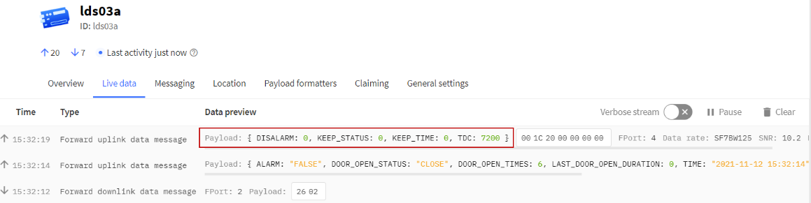
2.3.2 Sensor Configuration, FPORT=4
LDS03A will only send this command after getting the downlink command (0x26 02) from the server.
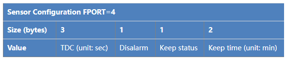
- TDC: (default: 0x001C20)
Uplink interval for the Open/Close Event, default value is 0x001C20 which is 7200 seconds = 2 hours.
- Disalarm: (default: 0)
If Disalarm = 1, LDS03A will only send uplink at every TDC periodically. This is normally use for pulse meter application, in this application, there are many open/close event, and platform only care about the total number of pulse.
If Disalarm = 0, LDS03A will send uplink at every TDC periodically and send data on each open/close event. This is useful for the application user need to monitor the open/close event in real-time.
Note: When Disalarm=0, a high frequently open/close event will cause lots of uplink and drain battery very fast.
- Keep Status & Keep Time
Shows the configure value of Alarm Base on Timeout Feature
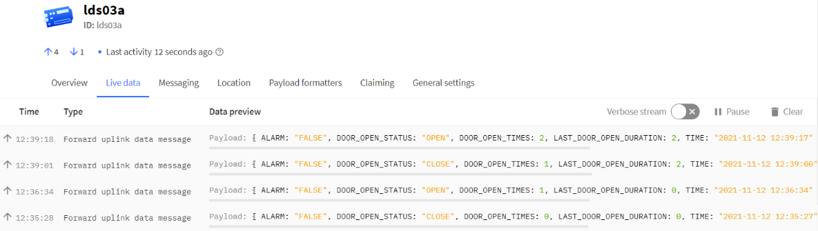
2.3.3 Real-Time Open/Close Status, Uplink FPORT=2
LDS03A will send this uplink after Device Status once join the LoRaWAN network successfully. And LDS03A will:
- periodically send this uplink every 2 hours, this interval can be changed.
- There is an Open/Close event.
Uplink Payload totals 11 bytes.
| Real-Time Open/Close Status, FPORT=2 | ||||
| Size (bytes) | 1 | 3 | 3 | 4 |
| Value | Status & Alarm | Total open door events | The last door open duration (unit: min) | Unix TimeStamp |
| Status & Alarm field | |||
| Size (bit) | 6 | 1 | 1 |
| Value | Reserve | Enable/disable Timeout Alarm 0: No Alarm; 1: Alarm | Status 0: Close, 1: Open |
2.3.4 Historical Door Open/Close Event, FPORT=3
LDS03A stores sensor values and users can retrieve these history values via the downlink command.
The historical payload includes one or multiplies entries and every entry has the same payload as Real-Time open/close status.
- Each data entry is 11 bytes and has the same structure as Real-Time open/close status, to save airtime and battery, LDS03A will send max bytes according to the current DR and Frequency bands.
For example, in the US915 band, the max payload for different DR is:
a) DR0: max is 11 bytes so one entry of data
b) DR1: max is 53 bytes so devices will upload 4 entries of data (total 44 bytes)
c) DR2: total payload includes 11 entries of data
d) DR3: total payload includes 22 entries of data.
If LDS03A doesn’t have any data in the polling time. It will uplink 11 bytes of 0
Downlink:
0x31 61 8E 57 40 61 8E 81 70 05
Uplink:
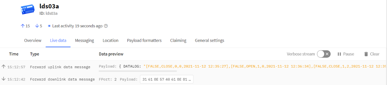
00 00 00 00 00 00 00 61 8E 5F 8F 01 00 00 01 00 00 00 61 8E 5F D2 00 00 00 01 00 00 02 61 8E 60 64 01 00 00 02 00 00 02 61 8E 60 75 00 00 00 02 00 00 01 61 8E 60 C6 00 00 00 02 00 00 01 61 8E 7B A7 01 00 00 03 00 00 01 61 8E 7F 38 00 00 00 03 00 00 02 61 8E 7F CE 01 00 00 04 00 00 02 61 8E 81 1B 00 00 00 04 00 00 00 61 8E 81 50
Parsed Value:
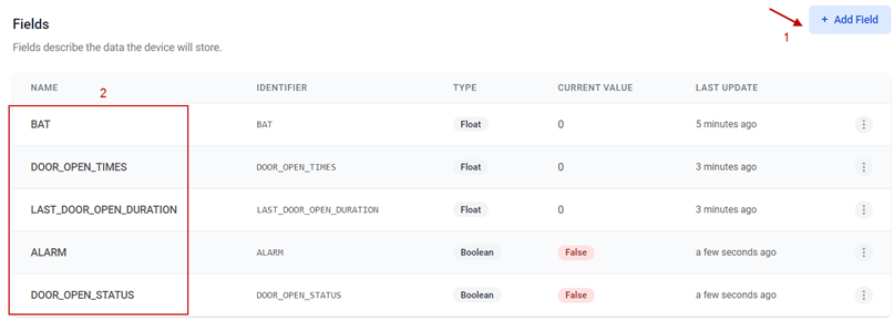
[ALARM, DOOR_OPEN_STATUS, DOOR_OPEN_TIMES,LAST_DOOR_OPEN_DURATION, TIME]
[FALSE, CLOSE, 0, 0, 2021-11-12 12:35:27],
[FALSE, OPEN, 1, 0, 2021-11-12 12:36:34],
[FALSE, CLOSE, 1, 2, 2021-11-12 12:39:00],
[FALSE, OPEN, 2, 2, 2021-11-12 12:39:17],
[FALSE, CLOSE, 2, 1, 2021-11-12 12:40:38],
[FALSE, CLOSE, 2, 1, 2021-11-12 14:35:19],
[FALSE, OPEN, 3, 1, 2021-11-12 14:50:32],
[FALSE, CLOSE, 3, 2, 2021-11-12 14:53:02],
[FALSE, OPEN, 4, 2, 2021-11-12 14:58:35],
[FALSE, CLOSE, 4, 0, 2021-11-12 14:59:28],
2.4 Datalog Feature
When a user wants to retrieve sensor value, he can send a poll command from the IoT platform to ask the sensor to send value in the required time slot.
2.4.1 Unix TimeStamp
LDS03A use Unix TimeStamp format based on
Users can get this time from the link: https://www.epochconverter.com/ :
Below is the converter example
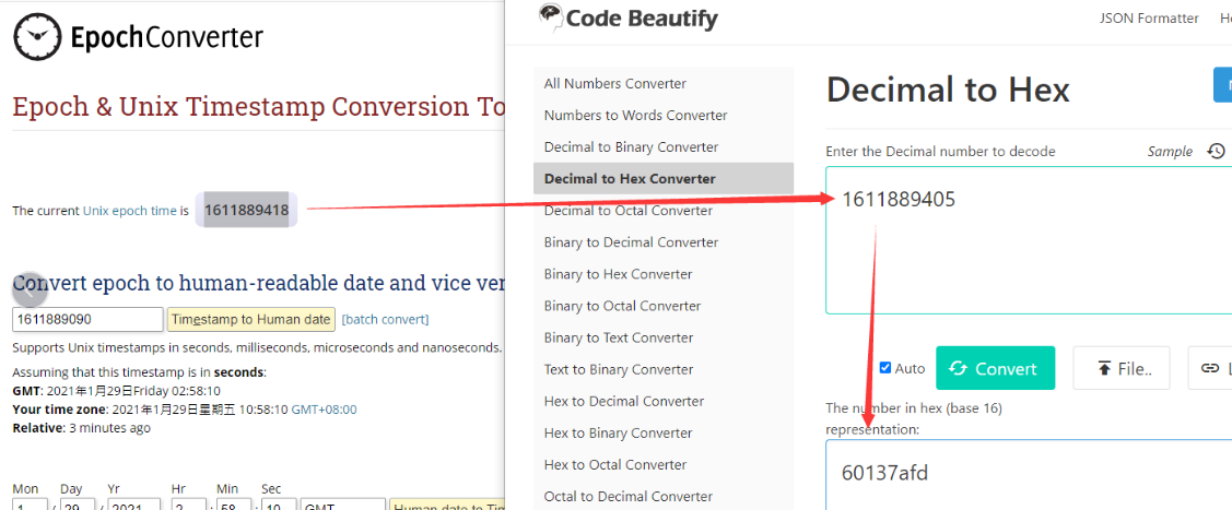
So, we can use AT+TIMESTAMP=1611889405 or downlink 3060137afd00 to set the current time 2021 – Jan -- 29 Friday 03:03:25
2.4.2 Set Device Time
There are two ways to set the device’s time:
1. Through LoRaWAN MAC Command (Default settings)
Users need to set SYNCMOD=1 to enable sync time via the MAC command.
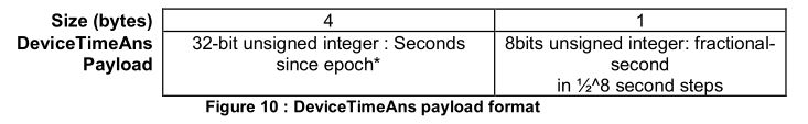
Once LDS03A Joined the LoRaWAN network, it will send the MAC command (DeviceTimeReq) and the server will reply with (DeviceTimeAns) to send the current time to LDS03A. If LDS03A fails to get the time from the server, LDS03A will use the internal time and wait for the next time request [via Device Status (FPORT=5)].
Note: LoRaWAN Server needs to support LoRaWAN v1.0.3(MAC v1.0.3) or higher to support this MAC command feature.
2. Manually Set Time
Users need to set SYNCMOD=0 to manual time, otherwise, the user set time will be overwritten by the time set by the server.
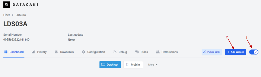
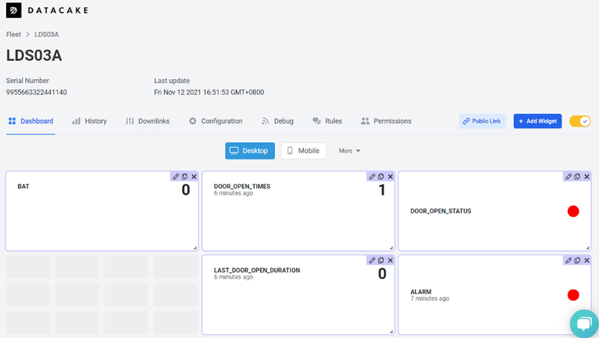
2.5 Show Data in DataCake IoT Server
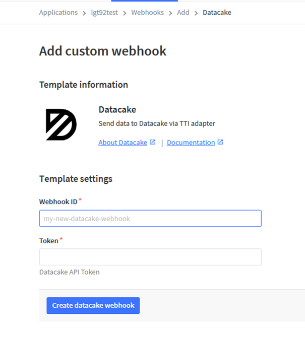
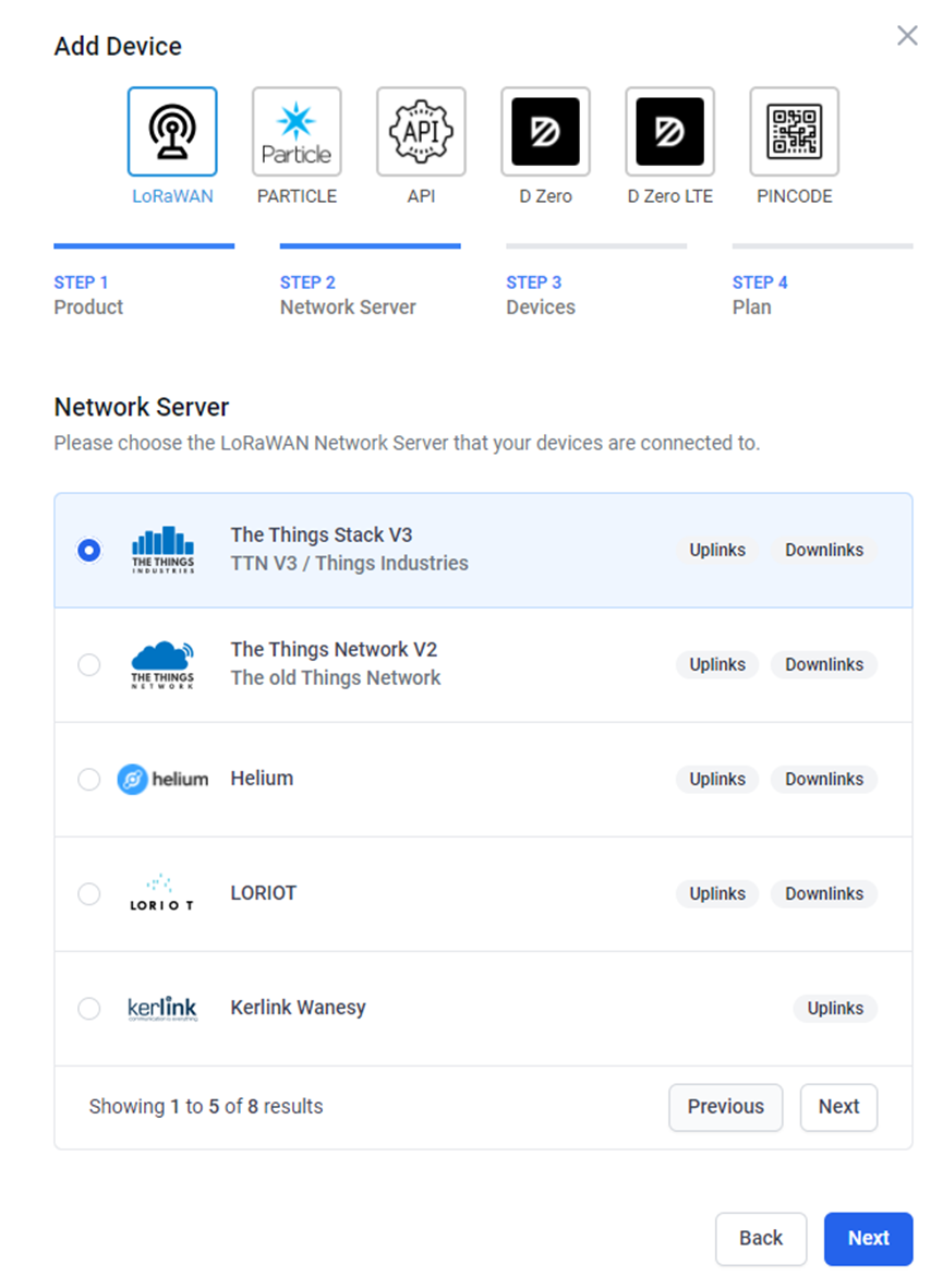
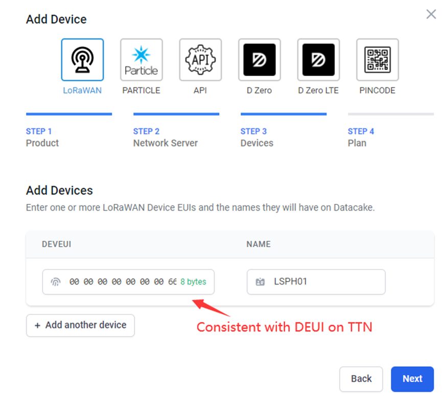
Datacake IoT platform provides a human-friendly interface to show the sensor data, once we have sensor data in TTN V3, we can use Datacake to connect to TTN V3 and see the data in Datacake. Below are the steps:
Step 1: Link TTNv3 to Datacake.https://docs.datacake.de/lorawan/lns/thethingsindustries#create-integration-on-tti
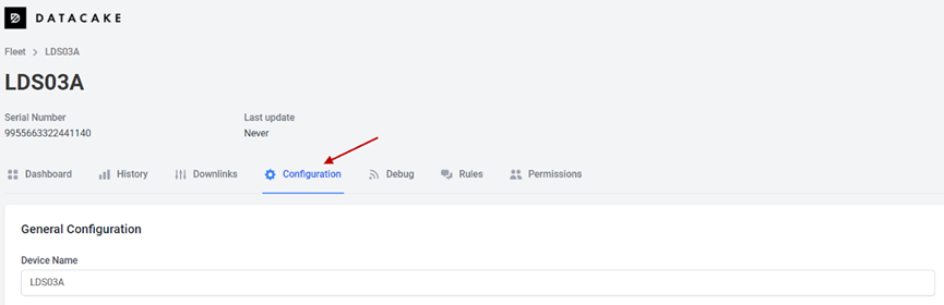
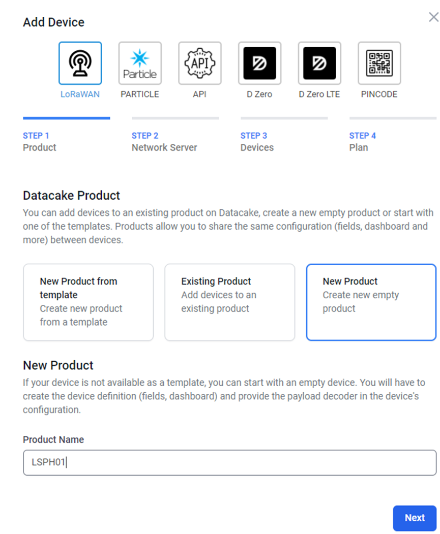
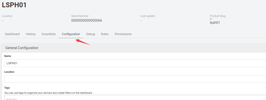
Step 2: Configure LDS03A in Datacake.
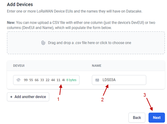

Step 3: Create an account or log in Datacake.
Step 4: Create LSPH01 product.
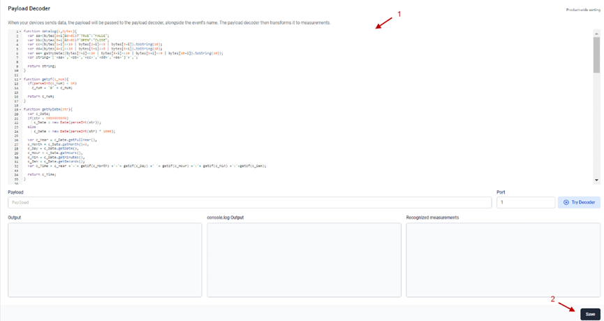
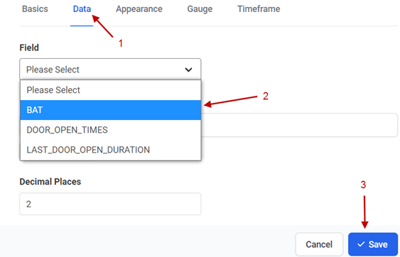
Step 5: add payload decode
Download Datacake decoder from: https://www.dragino.com/downloads/index.pHp?dir=LoRa_End_Node/LSPH01/Decoder/


2.6 Installation and Maintain
2.6.1 Before measurement
If the LSPH01 has more than 7 days not use or just clean the pH probe. User should put the probe inside pure water for more than 24 hours for activation. If no put in water, user need to put inside soil for more than 24 hours to ensure the measurement accuracy.
2.6.2 Measurement
Measurement the soil surface:
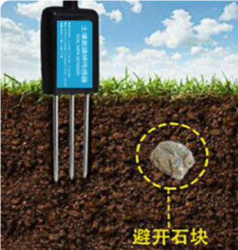
Choose the proper measuring position. Split the surface soil according to the measured deep.
Put pure water, or rainwater to make the soil of measurement point to moist mud. Remove rocks or hard things.
Slowly insert the probe to the measure point. Don’t use large force which will break the probe. Make sure not shake when inserting.
Put soil over the probe after insert. And start to measure.
Measurement inside soil:
Dig a hole with diameter > 20CM.
Insert the probe inside, method like measure the surface.
2.6.3 Maintain Probe
pH probe electrode is fragile and no strong. User must avoid strong force or hitting it.
After long time use (3~ 6 months). The probe electrode needs to be clean; user can use high grade sandpaper to polish it or put in 5% hydrochloric acid for several minutes. After the metal probe looks like new, user can use pure water to wash it.
Probe reference electrode is also no strong, need to avoid strong force or hitting.
User should keep reference electrode wet while not use.
Avoid the probes to touch oily matter. Which will cause issue in accuracy.
The probe is IP68 can be put in water.
2.7 Calibration
User can do calibration for the probe. It is limited to use below pH buffer solution to calibrate: 4.00, 6.86, 9.18. When calibration, user need to clean the electrode and put the probe in the pH buffer solution to wait the value stable ( a new clean electrode might need max 24 hours to be stable).
After stable, user can use below command to calibrate.
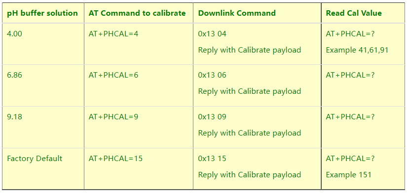
Calibration Payload
Size (bytes) | 1 | 1 | 1 | 7 | 1 |
|---|---|---|---|---|---|
| Value | PH4 Calibrate value | PH6.86 Calibrate value | PH9.18 Calibrate value | Reserve | Always 0x03 |
User can also send 0x14 downlink command to poll the current calibration payload.
- Reply to the confirmation package: 14 01
- Reply to non-confirmed packet: 14 00
2.8 Frequency Plans
The LSPH01 uses OTAA mode and below frequency plans by default. If user want to use it with different frequency plan, please refer the AT command sets.
2.8.1 EU863-870 (EU868)
Uplink:
868.1 - SF7BW125 to SF12BW125
868.3 - SF7BW125 to SF12BW125 and SF7BW250
868.5 - SF7BW125 to SF12BW125
867.1 - SF7BW125 to SF12BW125
867.3 - SF7BW125 to SF12BW125
867.5 - SF7BW125 to SF12BW125
867.7 - SF7BW125 to SF12BW125
867.9 - SF7BW125 to SF12BW125
868.8 - FSK
Downlink:
Uplink channels 1-9 (RX1)
869.525 - SF9BW125 (RX2 downlink only)
2.8.2 US902-928(US915)
Used in USA, Canada and South America. Frequency band as per definition in LoRaWAN 1.0.3 Regional document.
To make sure the end node supports all sub band by default. In the OTAA Join process, the end node will use frequency 1 from sub-band1, then frequency 1 from sub-band2, then frequency 1 from sub-band3, etc to process the OTAA join.
After Join success, the end node will switch to the correct sub band by:
- Check what sub-band the LoRaWAN server ask from the OTAA Join Accept message and switch to that sub-band
- Use the Join successful sub-band if the server doesn’t include sub-band info in the OTAA Join Accept message ( TTN v2 doesn't include)
2.8.3 CN470-510 (CN470)
Used in China, Default use CHE=1
Uplink:
486.3 - SF7BW125 to SF12BW125
486.5 - SF7BW125 to SF12BW125
486.7 - SF7BW125 to SF12BW125
486.9 - SF7BW125 to SF12BW125
487.1 - SF7BW125 to SF12BW125
487.3 - SF7BW125 to SF12BW125
487.5 - SF7BW125 to SF12BW125
487.7 - SF7BW125 to SF12BW125
Downlink:
506.7 - SF7BW125 to SF12BW125
506.9 - SF7BW125 to SF12BW125
507.1 - SF7BW125 to SF12BW125
507.3 - SF7BW125 to SF12BW125
507.5 - SF7BW125 to SF12BW125
507.7 - SF7BW125 to SF12BW125
507.9 - SF7BW125 to SF12BW125
508.1 - SF7BW125 to SF12BW125
505.3 - SF12BW125 (RX2 downlink only)
2.8.4 AU915-928(AU915)
Frequency band as per definition in LoRaWAN 1.0.3 Regional document.
To make sure the end node supports all sub band by default. In the OTAA Join process, the end node will use frequency 1 from sub-band1, then frequency 1 from sub-band2, then frequency 1 from sub-band3, etc to process the OTAA join.
After Join success, the end node will switch to the correct sub band by:
- Check what sub-band the LoRaWAN server ask from the OTAA Join Accept message and switch to that sub-band
- Use the Join successful sub-band if the server doesn’t include sub-band info in the OTAA Join Accept message ( TTN v2 doesn't include)
2.8.5 AS920-923 & AS923-925 (AS923)
Default Uplink channel:
923.2 - SF7BW125 to SF10BW125
923.4 - SF7BW125 to SF10BW125
Additional Uplink Channel:
(OTAA mode, channel added by JoinAccept message)
AS920~AS923 for Japan, Malaysia, Singapore:
922.2 - SF7BW125 to SF10BW125
922.4 - SF7BW125 to SF10BW125
922.6 - SF7BW125 to SF10BW125
922.8 - SF7BW125 to SF10BW125
923.0 - SF7BW125 to SF10BW125
922.0 - SF7BW125 to SF10BW125
AS923 ~ AS925 for Brunei, Cambodia, Hong Kong, Indonesia, Laos, Taiwan, Thailand, Vietnam:
923.6 - SF7BW125 to SF10BW125
923.8 - SF7BW125 to SF10BW125
924.0 - SF7BW125 to SF10BW125
924.2 - SF7BW125 to SF10BW125
924.4 - SF7BW125 to SF10BW125
924.6 - SF7BW125 to SF10BW125
Downlink:
Uplink channels 1-8 (RX1)
923.2 - SF10BW125 (RX2)
2.8.6 KR920-923 (KR920)
Default channel:
922.1 - SF7BW125 to SF12BW125
922.3 - SF7BW125 to SF12BW125
922.5 - SF7BW125 to SF12BW125
Uplink: (OTAA mode, channel added by JoinAccept message)
922.1 - SF7BW125 to SF12BW125
922.3 - SF7BW125 to SF12BW125
922.5 - SF7BW125 to SF12BW125
922.7 - SF7BW125 to SF12BW125
922.9 - SF7BW125 to SF12BW125
923.1 - SF7BW125 to SF12BW125
923.3 - SF7BW125 to SF12BW125
Downlink:
Uplink channels 1-7(RX1)
921.9 - SF12BW125 (RX2 downlink only; SF12BW125 might be changed to SF9BW125)
2.8.7 IN865-867 (IN865)
Uplink:
865.0625 - SF7BW125 to SF12BW125
865.4025 - SF7BW125 to SF12BW125
865.9850 - SF7BW125 to SF12BW125
Downlink:
Uplink channels 1-3 (RX1)
866.550 - SF10BW125 (RX2)
2.9 LED Indicator
The LSPH01 has an internal LED which is to show the status of different state.
- The sensor is detected when the device is turned on, and it will flash 4 times quickly when it is detected.
- Blink once when device transmit a packet.
2.10 Firmware Change Log
Firmware download link:
http://www.dragino.com/downloads/index.pHp?dir=LoRa_End_Node/LSPH01/Firmware/
Firmware Upgrade Method: Firmware Upgrade Instruction
3. Configure LSPH01 via AT Command or LoRaWAN Downlink
Use can configure LSPH01 via AT Command or LoRaWAN Downlink.
AT Command Connection: See FAQ.
LoRaWAN Downlink instruction for different platforms: IoT LoRaWAN Server
There are two kinds of commands to configure LSPH01, they are:
General Commands.
These commands are to configure:
General system settings like: uplink interval.
LoRaWAN protocol & radio related command.
They are same for all Dragino Device which support DLWS-005 LoRaWAN Stack. These commands can be found on the wiki:End Device AT Commands and Downlink Command
Commands special design for LSPH01
These commands only valid for LSPH01, as below:
3.1 Set Transmit Interval Time
Feature: Change LoRaWAN End Node Transmit Interval.
AT Command: AT+TDC
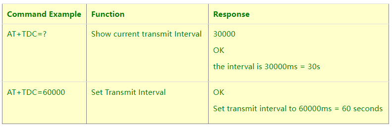
Downlink Command: 0x01
Format: Command Code (0x01) followed by 3 bytes time value.
If the downlink payload=0100003C, it means set the END Node’s Transmit Interval to 0x00003C=60(S), while type code is 01.
Example 1: Downlink Payload: 0100001E // Set Transmit Interval (TDC) = 30 seconds
Example 2: Downlink Payload: 0100003C // Set Transmit Interval (TDC) = 60 seconds
3.2 Set Interrupt Mode
Feature, Set Interrupt mode for GPIO_EXIT.
AT Command: AT+INTMOD
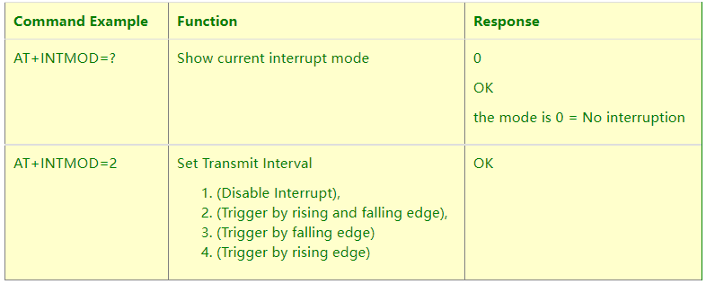
Downlink Command: 0x06
Format: Command Code (0x06) followed by 3 bytes.
This means that the interrupt mode of the end node is set to 0x000003=3 (rising edge trigger), and the type code is 06.
Example 1: Downlink Payload: 06000000 // Turn off interrupt mode
Example 2: Downlink Payload: 06000003 // Set the interrupt mode to rising edge trigger
3.3 Calibrate Sensor
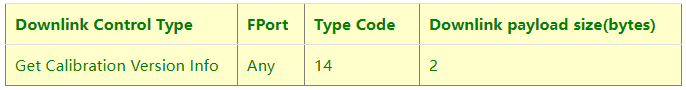
Detail See Calibration Guide for the user of 0x13 and 0x14 downlink commands
3.4 Get Firmware Version Info
Feature: use downlink to get firmware version.
Downlink Command: 0x26
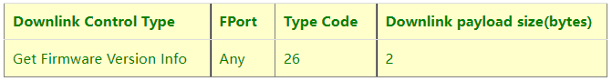
- Reply to the confirmation package: 26 01
- Reply to non-confirmed packet: 26 00
Device will send an uplink after got this downlink command. With below payload:
Configures info payload:
Size(bytes) | 1 | 1 | 1 | 1 | 1 | 5 | 1 |
|---|---|---|---|---|---|---|---|
| Value | Software Type | Frequency Band | Sub-band | Firmware Version | Sensor Type | Reserve | Message Type |
Software Type: Always 0x03 for LSPH01
Frequency Band:
*0x01: EU868
*0x02: US915
*0x03: IN865
*0x04: AU915
*0x05: KZ865
*0x06: RU864
*0x07: AS923
*0x08: AS923-1
*0x09: AS923-2
*0xa0: AS923-3
Sub-Band: value 0x00 ~ 0x08
Firmware Version: 0x0100, Means: v1.0.0 version
Sensor Type:
0x01: LSE01
0x02: LDDS75
0x03: LDDS20
0x04: LLMS01
0x05: LSPH01
0x06: LSNPK01
0x07: LDDS12
4. Battery & How to replace
4.1 Battery Type
LSPH01 is equipped with a 8500mAH ER26500 Li-SOCI2 battery. The battery is un-rechargeable battery with low discharge rate targeting for 8~10 years use. This type of battery is commonly used in IoT target for long-term running, such as water meter.
The discharge curve is not linear so can’t simply use percentage to show the battery level. Below is the battery performance.
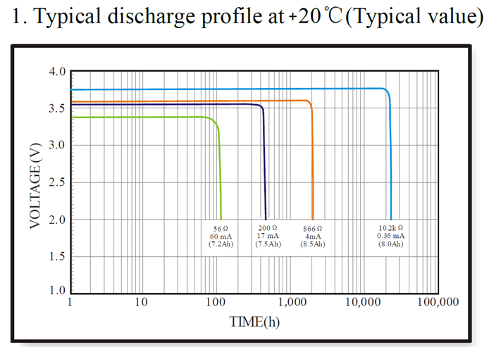
Minimum Working Voltage for the LSPH01:
LSPH01: 2.45v ~ 3.6v
4.2 Replace Battery
Any battery with range 2.45 ~ 3.6v can be a replacement. We recommend to use Li-SOCl2 Battery.
And make sure the positive and negative pins match.
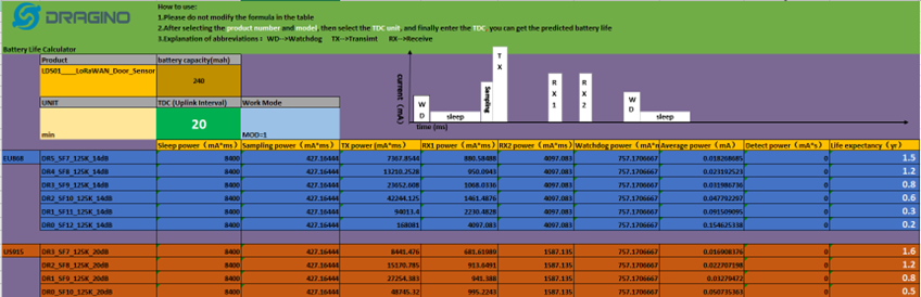
4.3 Power Consumption Analyze
Dragino Battery powered product are all runs in Low Power mode. We have an update battery calculator which base on the measurement of the real device. User can use this calculator to check the battery life and calculate the battery life if want to use different transmit interval.
Instruction to use as below:
Step 1: Downlink the up-to-date DRAGINO_Battery_Life_Prediction_Table.xlsx from:
https://www.dragino.com/downloads/index.pHp?dir=LoRa_End_Node/Battery_Analyze/
Step 2: Open it and choose
- Product Model
- Uplink Interval
- Working Mode
And the Life expectation in difference case will be shown on the right.
The battery related documents as below:
4.3.1 Battery Note
The Li-SICO battery is designed for small current / long period application. It is not good to use a high current, short period transmit method. The recommended minimum period for use of this battery is 5 minutes. If you use a shorter period time to transmit LoRa, then the battery life may be decreased.
4.3.2 Replace the battery
You can change the battery in the LSPH01.The type of battery is not limited as long as the output is between 3v to 3.6v. On the main board, there is a diode (D1) between the battery and the main circuit. If you need to use a battery with less than 3.3v, please remove the D1 and shortcut the two pads of it so there won’t be voltage drop between battery and main board.
The default battery pack of LSPH01 includes a ER26500 plus super capacitor. If user can’t find this pack locally, they can find ER26500 or equivalence, which will also work in most case. The SPC can enlarge the battery life for high frequency use (update period below 5 minutes)
5. Use AT Command
5.1 Access AT Commands
LSPH01 supports AT Command set in the stock firmware. You can use a USB to TTL adapter to connect to LSPH01 for using AT command, as below.
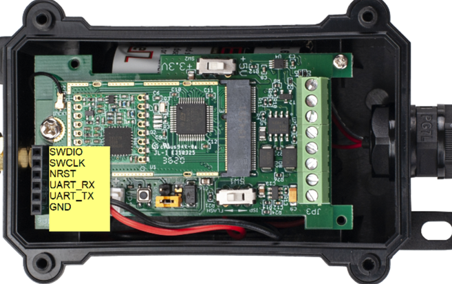
Connection:
USB TTL GND <----> GND
USB TTL TXD <----> UART_RXD
USB TTL RXD <----> UART_TXD
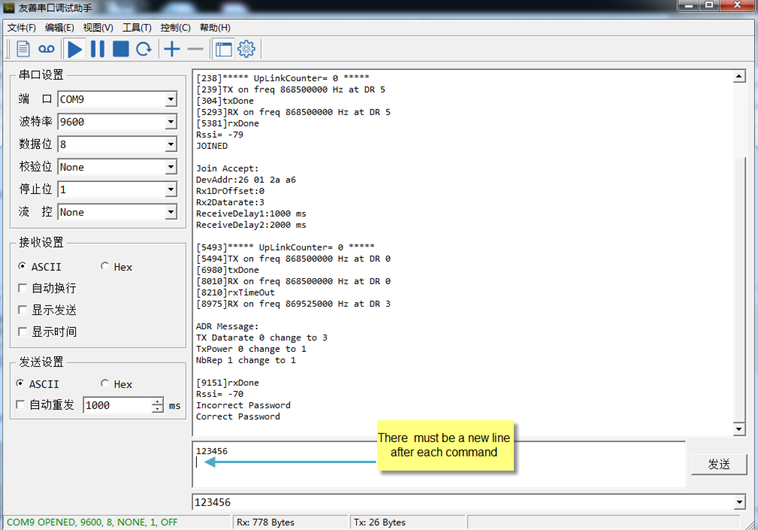
In the PC, you need to set the serial baud rate to 9600 to access the serial console for LSPH01. LSPH01 will output system info once power on as below:
Valid AT Command please check Configure Device.
6. FAQ
6.1 How to change the LoRa Frequency Bands/Region
You can follow the instructions for how to upgrade image.
When downloading the images, choose the required image file for download.
7. Trouble Shooting
7.1 AT Commands input doesn’t work
In the case if user can see the console output but can’t type input to the device. Please check if you already include the ENTER while sending out the command. Some serial tool doesn’t send ENTER while press the send key, user need to add ENTER in their string.
8. Order Info
Part Number: LSPH01-XX
XX: The default frequency band
- AS923: LoRaWAN AS923 band
- AU915: LoRaWAN AU915 band
- EU433: LoRaWAN EU433 band
- EU868: LoRaWAN EU868 band
- KR920: LoRaWAN KR920 band
- US915: LoRaWAN US915 band
- IN865: LoRaWAN IN865 band
- CN470: LoRaWAN CN470 band
9. Packing Info
Package Includes:
- LSPH01 LoRaWAN Soil Ph Sensor x 1
Dimension and weight:
- Device Size: cm
- Device Weight: g
- Package Size / pcs : cm
- Weight / pcs : g
10. Support
- Support is provided Monday to Friday, from 09:00 to 18:00 GMT+8. Due to different timezones we cannot offer live support. However, your questions will be answered as soon as possible in the before-mentioned schedule.
- Provide as much information as possible regarding your enquiry (product models, accurately describe your problem and steps to replicate it etc) and send a mail to support@dragino.com.