Table of Contents:
1. Introduction
1.1 What is LTC2 LoRaWAN Temperature Transmitter
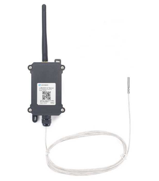
The Dragino LTC2 Industrial LoRaWAN Temperature Transmitter is designed to monitor temperature for different environment. It supports to read PT100 probe and convert the value to temperature and uplink to IoT server via LoRaWAN protocol.
LTC2 supports Datalog feature. User can retrieve the sensor value via LoRaWAN downlink command.
LTC2 is powered by 8500mA Li-SOCI2 battery for long time measurement. The battery can run 2~10 years depends on the network environment and working mode.
Each LTC2 has two internal 24-bit ADC interfaces and are calibrated on 12 set resistors to make sure the accuracy measurement on wide range.
LTC2 is LoRaWAN v1.0.3 compatible. Each LTC2 is pre-load with a set of unique keys for LoRaWAN registration, register these keys to local LoRaWAN server and it will auto connect after power on.
1.2 Features
- LoRaWAN v1.0.3 Class A
- max: 2 x monitor temperature channels
- Support 3 -wire PT-100
- 8500mAh Li-SOCI2 Battery
- Firmware upgrade via console
- Wall Mountable
- Configurable via LoRa or UART
- Datalog and retrieve via LoRaWAN
- Use pre-load PT100 probe or 3rd PT100 probe
- Factory calibration for different resistance range
- Support accuracy measure of resistance and upload
- Battery Monitoring and upload
1.3 Applications
- Logistics and Supply Chain Management
- Food management
- Cold chains solution
- Industrial Monitoring and Control
1.4 Hardware Change log
LTC2 v1.0: Release.
1.5 Pin Definitions and Switch
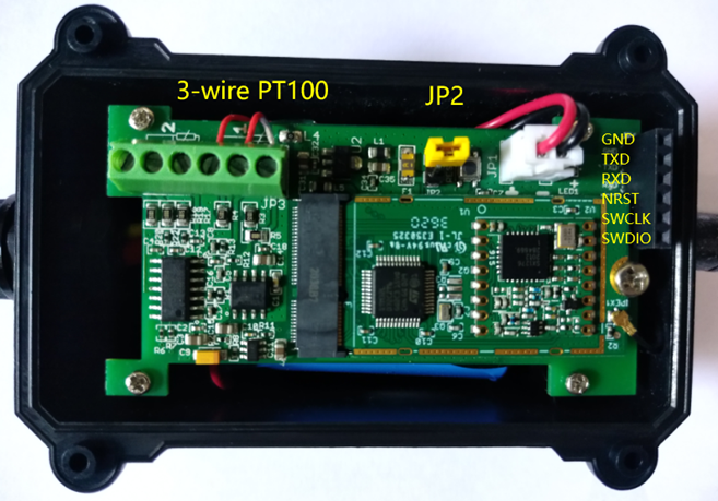
1.5.1 Jumper JP2 ( Power ON)
Put a jumper on JP2 will power on the LTC2.
1.5.2 LED
The LED will flash in below case.
- Send an uplink packet
1.5.3 PT100 Interfaces
There are two independent channels to connect 2 x PT100 probes.
Each channel has 3-wire connection for 3-wire PT100 probes.
1.5.4 Reset Button
Press this button will reboot the LTC2
1.6 Probe Variant
LTC2 provide default probe version. See below for the variant:
| Model | Photo | Description |
|---|---|---|
| LTC2-SI |  | Standard IP68 Probe Version
|
| LTC2-LT | 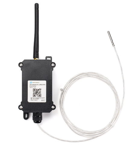 | Low Temperature Version
|
| LTC2-FS | 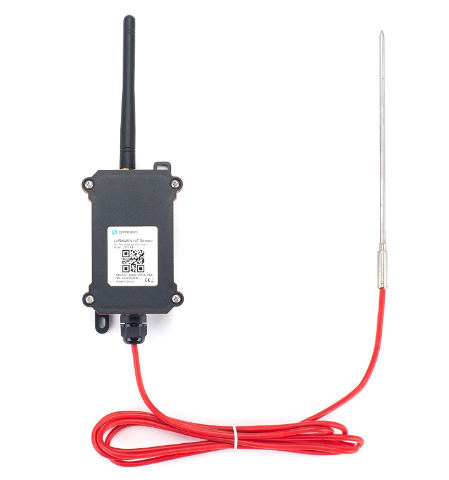 | Food Safety Version
|
| LTC2-FT | 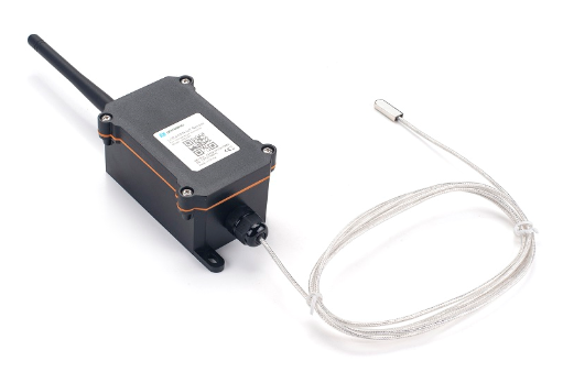 | Flat Type Version
|
| LTC2-HT | 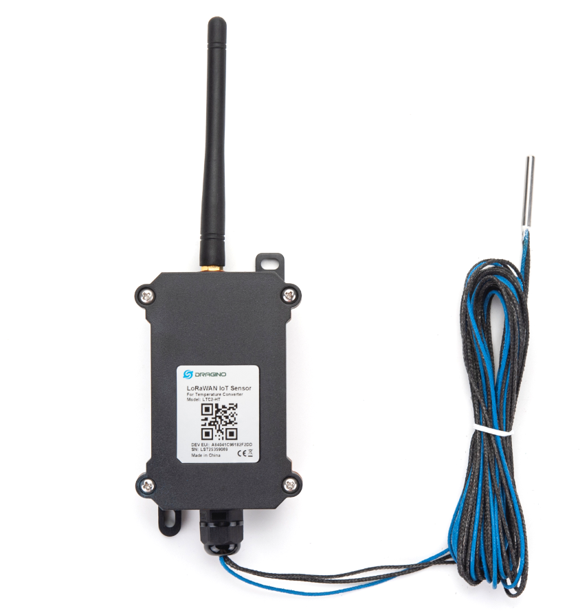 | High Temperature Version
Suitable Environment: High Temperature |
| LTC2-NA | 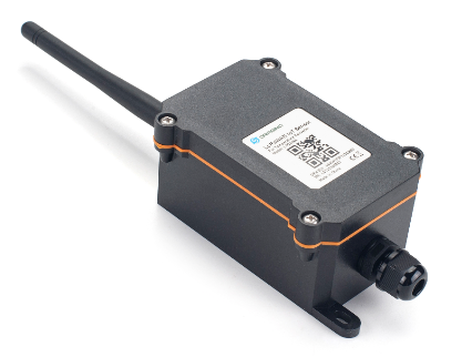 | No Probe version:
Connect to customized probe |
2. How to use LTC2?
2.1 Connect to PT100 sensors
LTC2 has different probe option provided for ordering, if user has LTC2 with probe, just skip this step. If user want to connect to a 3rd party PT100 probe, please see CONNECT A 3rd PARTY PT100 probe.
2.2 How it works?
The LTC2 is working in LoRaWAN OTAA Class A mode. Each LTC2 is shipped with a worldwide unique set of OTAA and ABP keys. User needs to input the OTAA or ABP keys in the LoRaWAN network server so to register. LTC2 will join the LoRaWAN network and start to transmit data. The default period for each uplink is 20 minutes.
On each uplink, LTC2 will check its two ADC Interfaces and get the temperature from the sensor and send out to server.
2.3 Quick guide to connect to LoRaWAN server (OTAA)
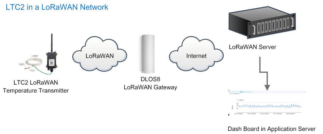
Here is an example for how to join the TTN v3 LoRaWAN Server. Below is the network structure, in this demo we use DLOS8 as LoRaWAN gateway.
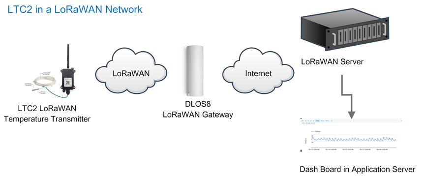

The DLOS8 is already set to connect to TTN . Rest we need to is register the LTC2 to TTN v3:
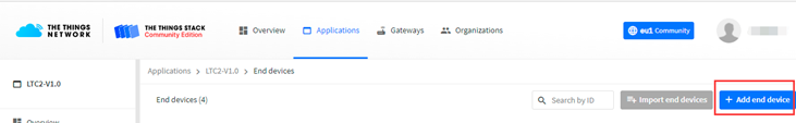
2.3.1 Step 1: Create a device in TTN with the OTAA keys from LTC2
Below is TTN screen shot:
- Create Application first.
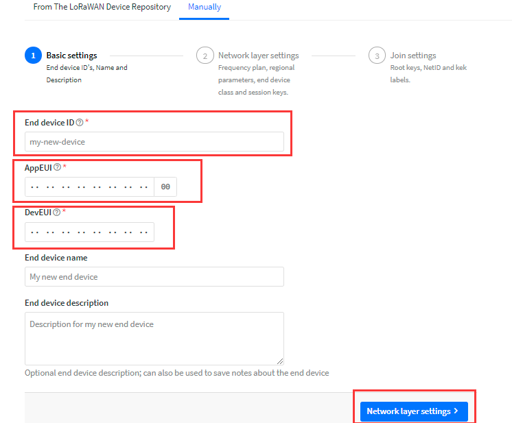
- Manually Add a LoRaWAN End Device device. Choose OTAA and MAC v1.0.3
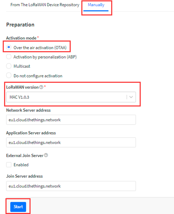
Input the OTAA keys for LTC2.
Each LTC2 is shipped with a sticker with the default device EUI as below:
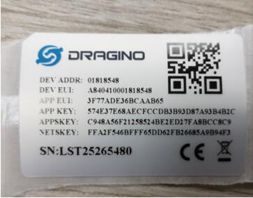
- Input these keys to device portal.
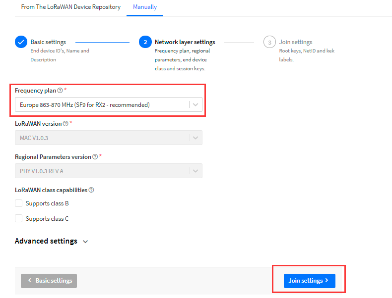
- Choose the Frequency band for this end node.
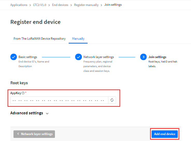
- Input APP Key in this page as well.
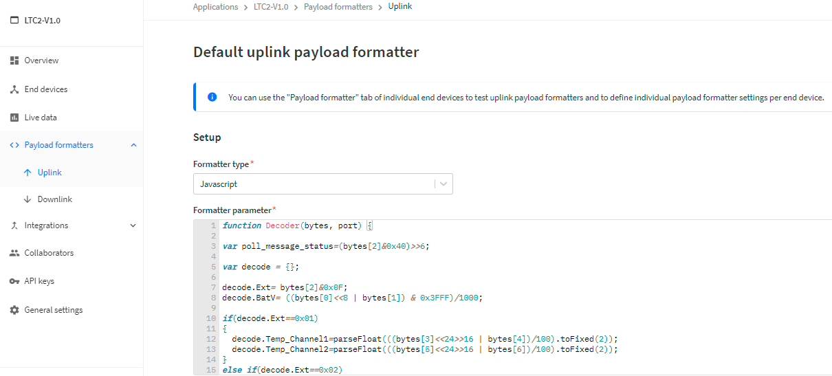
Add payload formatter So TTNv3 knows how to parse the LTC2 upload value.
The payload for TTN can be found at below link:
https://www.dragino.com/downloads/downloads/LoRa_End_Node/LTC2/Decoder/
2.3.2 Step 2: Power on LTC2
LTC2 is power off when ship from factory.
Put a Jumper on JP2 to power on the device.

After power on, LTC2 will auto join to TTN network via the LoRaWAN coverage by DLOS8. After join success, LTC2 will start to update message to IoT server.
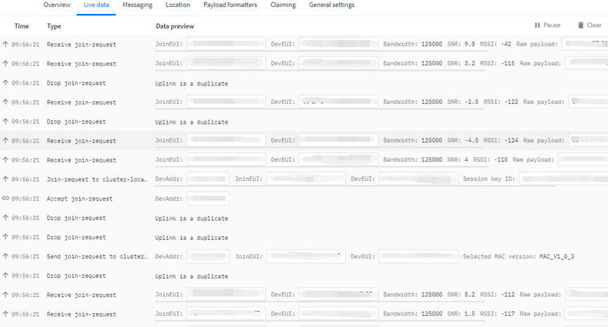
Below is an example uplink message which shows the LTC2 is sending Join Request to TTNv3.
After join successful, LTC2 will send uplink message with the sensor value.
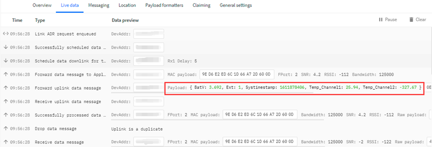
Above value shows Channel1 detect 25.94 degree. There is no PT100 connected on Channel 2, so it shows -327.67.
2.4 Uplink Payload
Below is the uplink payload which shows
Size (bytes) | 2 | 1 | 2 | 2 | 4 |
|---|---|---|---|---|---|
| Value |
BAT
Ex1: 0x0E3C ⇒ 3644 (mV) = 3.644 V
Status & EXT
| Bits | 7 | 6 | 5 | 4 | [3:0] |
| Status & Ext | Not Defined | Poll Message Flag | Sync time OK | Unix Time Request | Ext: 0b(1001) |
- Poll Message Flag: 1: This message is a poll message reply, 0: means this is a normal uplink.
- Sync time OK: 1: Set time ok,0: N/A. After time SYNC request is send, device will set this bit to 0 until got the time stamp from application server.
- Unix Time Request: 1: Request server downlink Unix time, 0 : N/A. In this mode, LTC2 will set this bit to 1 every 10 day to request a time SYNC. (AT+SYNCMOD to set this)
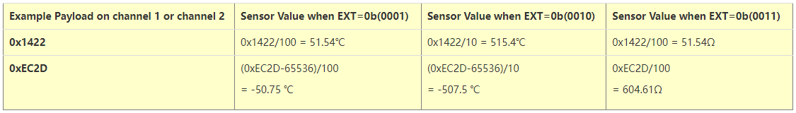
- EXT: The decode method for Channel 1 data and Channel 2 data
- 0b(0001): Upload PT100 temperature, with 2 decimals, range: -327.67 ~ 327.67 ℃
- 0b(0010): Upload PT100 temperature, with 1 decimals, range: -3276.7 ~ 3276.7 ℃
- 0b(0011): Upload Resistance instead of Temperature, range: -327.67~ 327.67 ohm
Channel1 data and Channel 2 data
Unix TimeStamp
Refer to Datalog feature.
Example Uplink Payload:
Uplink payload example 1: 0CE9011422EC2D6073E83B
- Bat voltage:0x0CE9 =3305mV
- Ext=0x01
- Channel1 temp=0x1422/100=51.54 ℃
- Channel2 temp=(0xEC2D-65536)/100=-50.75 ℃
- System timestamp=0x6073E83B= 1618208827(UTC)
Uplink payload example 2: 0CED020203FE056073E697
- Bat voltage:0x0CED =3309mV
- Ext=0x02
- Channel1 temp=0x0203/10=515.4 ℃
- Channel2 temp=(0xFE05-65536)/10=-507.5 ℃
- System timestamp=0x6073E697=1618208407(UTC)
Uplink payload example 3 : 0CE9032EDE1F406073E967
- Bat voltage:0x0CE9 =3305mV
- Ext=0x03
- Channel1 res=0x2EDE/100=119.98 ohm
- Channel2 res=0x1F40/100=80.00 ohm
- System timestamp=0x6073E967= 1618209127(UTC)
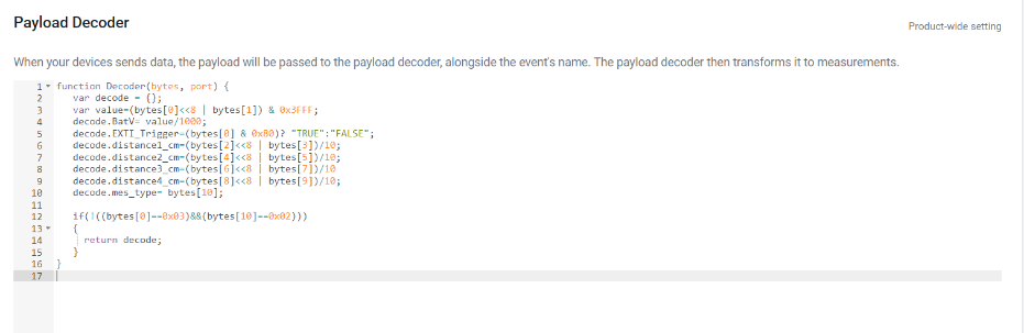
2.4.5 Decode payload in The Things Network
While using TTN network, you can add the payload format to decode the payload.
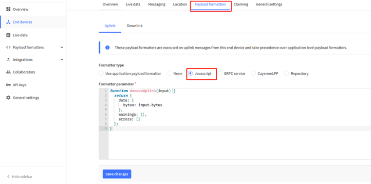
The payload decoder function for TTN is here:
LDDS04 TTN Payload Decoder: https://www.dragino.com/downloads/index.php?dir=LoRa_End_Node/LDDS04/Decoder/
function Decoder(bytes, port) {
var decode = {};
var value=(bytes[0]<<8 | bytes[1]) & 0x3FFF;
decode.BatV= value/1000;
decode.EXTI_Trigger=(bytes[0] & 0x80)? "TRUE":"FALSE";
decode.distance1_cm=(bytes[2]<<8 | bytes[3])/10;
decode.distance2_cm=(bytes[4]<<8 | bytes[5])/10;
decode.distance3_cm=(bytes[6]<<8 | bytes[7])/10
decode.distance4_cm=(bytes[8]<<8 | bytes[9])/10;
decode.mes_type= bytes[10];
if(!((bytes[0]==0x03)&&(bytes[10]==0x02)))
{
return decode;
}
}
2.5 Uplink Interval
The LDDS04 by default uplink the sensor data every 20 minutes. User can change this interval by AT Command or LoRaWAN Downlink Command. See this link: Change Uplink Interval
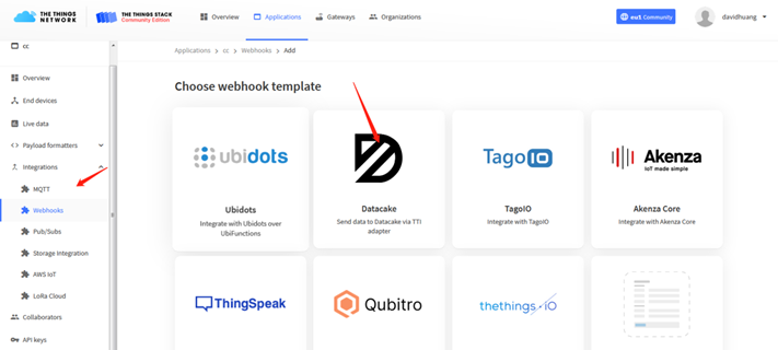
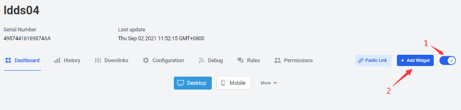
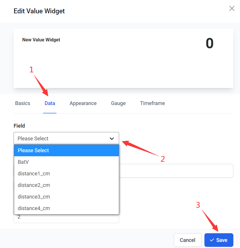
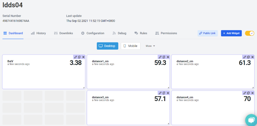
2.6 Show Data in DataCake IoT Server
DATACAKE provides a human friendly interface to show the sensor data, once we have data in TTN, we can use DATACAKE to connect to TTN and see the data in DATACAKE. Below are the steps:
Step 1: Be sure that your device is programmed and properly connected to the network at this time.
Step 2: To configure the Application to forward data to DATACAKE you will need to add integration. To add the DATACAKE integration, perform the following steps:
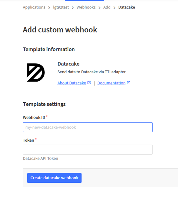
Step 3: Create an account or log in Datacake.
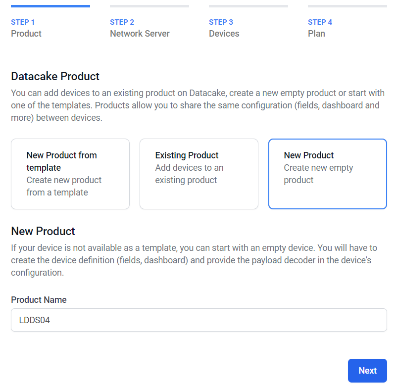
Step 4: Create LDDS04 product.
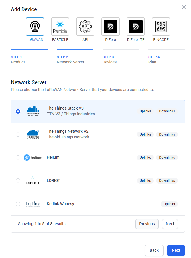
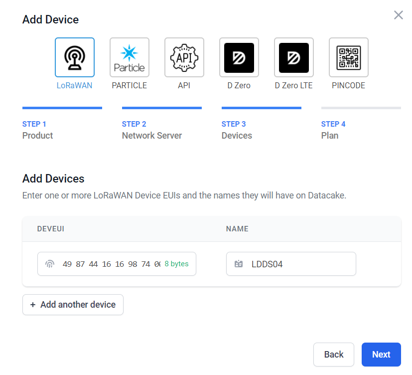
Step 5: add payload decode
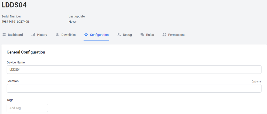
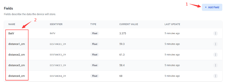
After added, the sensor data arrive TTN, it will also arrive and show in Datacake.

2.7 Frequency Plans
The LDDS45 uses OTAA mode and below frequency plans by default. If user want to use it with different frequency plan, please refer the AT command sets.
2.7.1 EU863-870 (EU868)
Uplink:
868.1 - SF7BW125 to SF12BW125
868.3 - SF7BW125 to SF12BW125 and SF7BW250
868.5 - SF7BW125 to SF12BW125
867.1 - SF7BW125 to SF12BW125
867.3 - SF7BW125 to SF12BW125
867.5 - SF7BW125 to SF12BW125
867.7 - SF7BW125 to SF12BW125
867.9 - SF7BW125 to SF12BW125
868.8 - FSK
Downlink:
Uplink channels 1-9 (RX1)
869.525 - SF9BW125 (RX2 downlink only)
2.7.2 US902-928(US915)
Used in USA, Canada, and South America. Frequency band as per definition in LoRaWAN 1.0.3 Regional document.
To make sure the end node supports all sub band by default. In the OTAA Join process, the end node will use frequency 1 from sub-band1, then frequency 1 from sub-band2, then frequency 1 from sub-band3, etc to process the OTAA join.
After Join success, the end node will switch to the correct sub band by:
Check what sub-band the LoRaWAN server ask from the OTAA Join Accept message and switch to that sub-band
Use the Join successful sub-band if the server doesn’t include sub-band info in the OTAA Join Accept message ( TTN v2 doesn't include)
2.7.3 CN470-510 (CN470)
Used in China, Default use CHE=1
Uplink:
486.3 - SF7BW125 to SF12BW125
486.5 - SF7BW125 to SF12BW125
486.7 - SF7BW125 to SF12BW125
486.9 - SF7BW125 to SF12BW125
487.1 - SF7BW125 to SF12BW125
487.3 - SF7BW125 to SF12BW125
487.5 - SF7BW125 to SF12BW125
487.7 - SF7BW125 to SF12BW125
Downlink:
506.7 - SF7BW125 to SF12BW125
506.9 - SF7BW125 to SF12BW125
507.1 - SF7BW125 to SF12BW125
507.3 - SF7BW125 to SF12BW125
507.5 - SF7BW125 to SF12BW125
507.7 - SF7BW125 to SF12BW125
507.9 - SF7BW125 to SF12BW125
508.1 - SF7BW125 to SF12BW125
505.3 - SF12BW125 (RX2 downlink only)
2.7.4 AU915-928(AU915)
Frequency band as per definition in LoRaWAN 1.0.3 Regional document.
To make sure the end node supports all sub band by default. In the OTAA Join process, the end node will use frequency 1 from sub-band1, then frequency 1 from sub-band2, then frequency 1 from sub-band3, etc to process the OTAA join.
After Join success, the end node will switch to the correct sub band by:
Check what sub-band the LoRaWAN server ask from the OTAA Join Accept message and switch to that sub-band
Use the Join successful sub-band if the server doesn’t include sub-band info in the OTAA Join Accept message ( TTN v2 doesn't include)
2.7.5 AS920-923 & AS923-925 (AS923)
Default Uplink channel:
923.2 - SF7BW125 to SF10BW125
923.4 - SF7BW125 to SF10BW125
Additional Uplink Channel:
(OTAA mode, channel added by JoinAccept message)
AS920~AS923 for Japan, Malaysia, Singapore:
922.2 - SF7BW125 to SF10BW125
922.4 - SF7BW125 to SF10BW125
922.6 - SF7BW125 to SF10BW125
922.8 - SF7BW125 to SF10BW125
923.0 - SF7BW125 to SF10BW125
922.0 - SF7BW125 to SF10BW125
AS923 ~ AS925 for Brunei, Cambodia, Hong Kong, Indonesia, Laos, Taiwan, Thailand, Vietnam:
923.6 - SF7BW125 to SF10BW125
923.8 - SF7BW125 to SF10BW125
924.0 - SF7BW125 to SF10BW125
924.2 - SF7BW125 to SF10BW125
924.4 - SF7BW125 to SF10BW125
924.6 - SF7BW125 to SF10BW125
Downlink:
Uplink channels 1-8 (RX1)
923.2 - SF10BW125 (RX2)
2.7.6 KR920-923 (KR920)
Default channel:
922.1 - SF7BW125 to SF12BW125
922.3 - SF7BW125 to SF12BW125
922.5 - SF7BW125 to SF12BW125
Uplink: (OTAA mode, channel added by JoinAccept message)
922.1 - SF7BW125 to SF12BW125
922.3 - SF7BW125 to SF12BW125
922.5 - SF7BW125 to SF12BW125
922.7 - SF7BW125 to SF12BW125
922.9 - SF7BW125 to SF12BW125
923.1 - SF7BW125 to SF12BW125
923.3 - SF7BW125 to SF12BW125
Downlink:
Uplink channels 1-7(RX1)
921.9 - SF12BW125 (RX2 downlink only; SF12BW125 might be changed to SF9BW125)
2.7.7 IN865-867 (IN865)
Uplink:
865.0625 - SF7BW125 to SF12BW125
865.4025 - SF7BW125 to SF12BW125
865.9850 - SF7BW125 to SF12BW125
Downlink:
Uplink channels 1-3 (RX1)
866.550 - SF10BW125 (RX2)
2.8 LED Indicator
The LDDS04 has an internal LED which is used to show the status of different state.
- After LDDS04 is turned on, if the 4 channels converter is detected, the LED will flash 4 times quickly.
- Blink once when device transmit a packet.
- Solid ON for Five Seconds when OTAA Join Successfully.
2.9 Firmware Change Log
Firmware download link: http://www.dragino.com/downloads/index.php?dir=LoRa_End_Node/LDDS04/Firmware/
Firmware Upgrade Method: Firmware Upgrade Instruction
3. Configure LDDS04 via AT Command or LoRaWAN Downlink
Use can configure LDDS04 via AT Command or LoRaWAN Downlink.
AT Command Connection: See FAQ.
LoRaWAN Downlink instruction for different platforms: IoT LoRaWAN Server
There are two kinds of commands to configure LDDS04, they are:
General Commands.
These commands are to configure:
General system settings like: uplink interval.
LoRaWAN protocol & radio related command.
They are same for all Dragino Device which support DLWS-005 LoRaWAN Stack. These commands can be found on the wiki: End Device AT Commands and Downlink Command
Commands special design for LDDS04
These commands only valid for LDDS04, as below:
3.1 Set Transmit Interval Time
Feature: Change LoRaWAN End Node Transmit Interval.
AT Command: AT+TDC
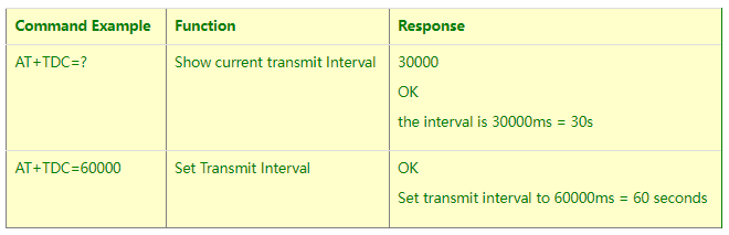
Downlink Command: 0x01
Format: Command Code (0x01) followed by 3 bytes time value.
If the downlink payload=0100003C, it means set the END Node's Transmit Interval to 0x00003C=60(S), while type code is 01.
- Example 1: Downlink Payload: 0100001E // Set Transmit Interval (TDC) = 30 seconds
- Example 2: Downlink Payload: 0100003C // Set Transmit Interval (TDC) = 60 seconds
3.2 Set Interrupt Mode
Feature, Set Interrupt mode for GPIO_EXIT.
Downlink Command: AT+INTMOD
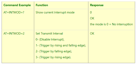
Downlink Command: 0x06
Format: Command Code (0x06) followed by 3 bytes.
This means that the interrupt mode of the end node is set to 0x000003=3 (rising edge trigger), and the type code is 06.
Example 1: Downlink Payload: 06000000 // Turn off interrupt mode
Example 2: Downlink Payload: 06000003 // Set the interrupt mode to rising edge trigger
3.3 Get Firmware Version Info
Feature: use downlink to get firmware version.
Downlink Command: 0x26
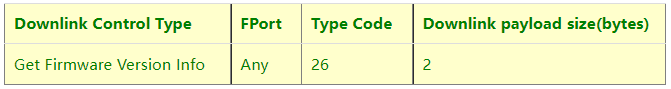
- Reply to the confirmation package: 26 01
- Reply to non-confirmed packet: 26 00
Device will send an uplink after got this downlink command. With below payload:
Configures info payload:
Size(bytes) | 1 | 1 | 1 | 2 | 1 | 4 | 1 |
|---|---|---|---|---|---|---|---|
| Value | Software Type | Frequency Band | Sub-band | Firmware Version | Sensor Type | Reserve | Message Type |
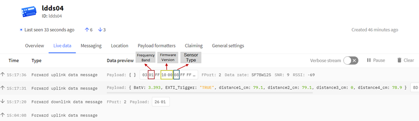
Software Type: Always 0x03 for LDDS04
Frequency Band:
*0x01: EU868
*0x02: US915
*0x03: IN865
*0x04: AU915
*0x05: KZ865
*0x06: RU864
*0x07: AS923
*0x08: AS923-1
*0x09: AS923-2
*0xa0: AS923-3
Sub-Band: value 0x00 ~ 0x08
Firmware Version: 0x0100, Means: v1.0.0 version
Sensor Type:
0x01: LSE01
0x02: LDDS75
0x03: LDDS20
0x04: LLMS01
0x05: LSPH01
0x06: LSNPK01
0x07: LLDS12
4. Battery & How to replace
4.1 Battery Type
LDDS04 is equipped with a 8500mAH ER26500 Li-SOCI2 battery. The battery is un-rechargeable battery with low discharge rate targeting for 8~10 years use. This type of battery is commonly used in IoT target for long-term running, such as water meter.
The discharge curve is not linear so can’t simply use percentage to show the battery level. Below is the battery performance.
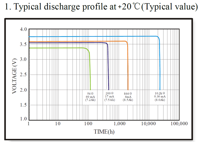
Minimum Working Voltage for the LDDS04:
LDDS04: 2.45v ~ 3.6v
4.2 Replace Battery
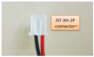
Any battery with range 2.45 ~ 3.6v can be a replacement. We recommend to use Li-SOCl2 Battery.
And make sure the positive and negative pins match.
4.3 Power Consumption Analyze
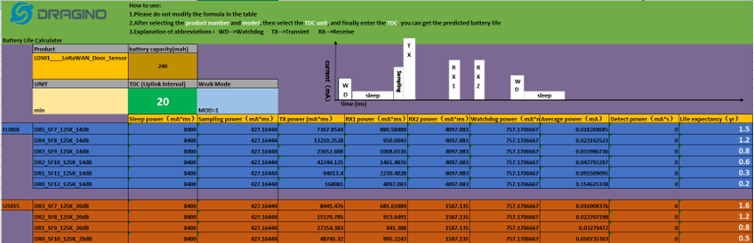
Dragino Battery powered product are all runs in Low Power mode. We have an update battery calculator which base on the measurement of the real device. User can use this calculator to check the battery life and calculate the battery life if want to use different transmit interval.
Instruction to use as below:
Step 1 : Downlink the up-to-date DRAGINO_Battery_Life_Prediction_Table.xlsx from:
https://www.dragino.com/downloads/index.pHp?dir=LoRa_End_Node/Battery_Analyze/
Step 2 : Open it and choose
- Product Model
- Uplink Interval
- Working Mode
And the Life expectation in difference case will be shown on the right.
![]()
The battery related documents as below:
4.3.1 Battery Note
The Li-SICO battery is designed for small current / long period application. It is not good to use a high current, short period transmit method. The recommended minimum period for use of this battery is 5 minutes. If you use a shorter period time to transmit LoRa, then the battery life may be decreased.
4.3.2 Replace the battery
You can change the battery in the LSPH01.The type of battery is not limited as long as the output is between 3v to 3.6v. On the main board, there is a diode (D1) between the battery and the main circuit. If you need to use a battery with less than 3.3v, please remove the D1 and shortcut the two pads of it so there won’t be voltage drop between battery and main board.
The default battery pack of LSPH01 includes a ER26500 plus super capacitor. If user can’t find this pack locally, they can find ER26500 or equivalence, which will also work in most case. The SPC can enlarge the battery life for high frequency use (update period below 5 minutes).
5. Use AT Command
5.1 Access AT Commands
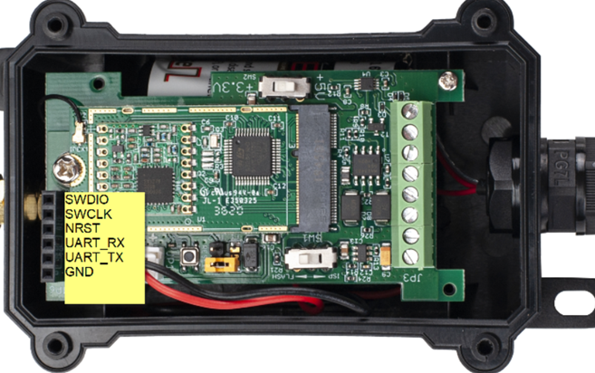
LDDS04 supports AT Command set in the stock firmware. You can use a USB to TTL adapter to connect to LDDS04 for using AT command, as below.
![]()
Connection:
USB TTL GND <----> GND
USB TTL TXD <----> UART_RXD
USB TTL RXD <----> UART_TXD
In the PC, you need to set the serial baud rate to 9600 to access the serial console for LDDS04.
LDDS04 will output system info once power on as below:
![]()
Valid AT Command please check Configure Device.
6. FAQ
6.1 How to change the LoRa Frequency Bands/Region
You can follow the instructions for how to upgrade image.
When downloading the images, choose the required image file for download.
7. Trouble Shooting
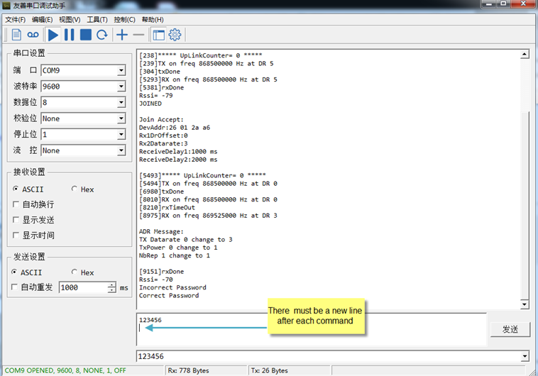
7.1 AT Command input doesn't work
In the case if user can see the console output but can’t type input to the device. Please check if you already include the ENTER while sending out the command. Some serial tool doesn’t send ENTER while press the send key, user need to add ENTER in their string.
8. Order Info
8.1 Main Device LDDS04
Part Number : LDDS04-XX
XX: The default frequency band
- AS923 : LoRaWAN AS923 band
- AU915 : LoRaWAN AU915 band
- EU433 : LoRaWAN EU433 band
- EU868 : LoRaWAN EU868 band
- KR920 : LoRaWAN KR920 band
- US915 : LoRaWAN US915 band
- IN865 : LoRaWAN IN865 band
- CN470 : LoRaWAN CN470 band
8.2 Probe Model
Detail See Probe Option Section
- A01A-15
- A02-15
- A13-15
- A16-15
9. Packing Info
Package Includes:
- LDDS04 LoRaWAN 4-Channels Distance Sensor x 1
Dimension and weight:
- Device Size: cm
- Device Weight: g
- Package Size / pcs : cm
- Weight / pcs : g
10. Support
- Support is provided Monday to Friday, from 09:00 to 18:00 GMT+8. Due to different timezones we cannot offer live support. However, your questions will be answered as soon as possible in the before-mentioned schedule.
- Provide as much information as possible regarding your enquiry (product models, accurately describe your problem and steps to replicate it etc) and send a mail to support@dragino.com.