Table of Contents:
1. Introduction
1.1 What is LMDS120 Microwave Radar DistanceSensor
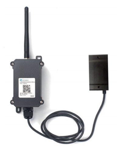
The Dragino LMDS120 is a LoRaWAN Microwave Radar distance sensor. It uses use Microwave Radar to detect the distance between sensor and different objects. Different from ultrosonic or Lidar measurement. Microwave Radar is more reliable for condensation / dusty environment. It can sense correct distance even there is water or think dust on top of the sensor.
The LMDS120 can be applied to scenarios such as horizontal distance measurement, parking management system, object proximity and presence detection, intelligent trash can management system, robot obstacle avoidance, automatic control, sewer, etc.
The LoRa wireless technology used in LMDS120 allows device to send data and reach extremely long ranges at low data-rates. It provides ultra-long range spread spectrum communication and high interference immunity whilst minimizing current consumption.
LMDS120 is powered by 8500mAh Li-SOCI2 battery, it is designed for long term use up to 5 years.
Each LMDS120 is pre-load with a set of unique keys for LoRaWAN registrations, register these keys to local LoRaWAN server and it will auto connect after power on.

1.2 Features
- LoRaWAN 1.0.3 Class A
- Ultra-low power consumption
- 60Ghz Microwave Radar for distance detection
- Monitor Battery Level
- Bands: CN470/EU433/KR920/US915/EU868/AS923/AU915/IN865
- AT Commands to change parameters
- Uplink on periodically
- Downlink to change configure
- 8500mAh Battery for long term use
- Wall Mountable
- Outdoor Use
1.3 Radar probe specification
- Measuring Method: FMCW
- Frequency: 60 GHz
- Measure Range : 15cm ~ 1200cm
- Accuracy:± (3mm + S*02%). S: Measure Value
- Resolution: 0.01m
- Measurement Angle : 25 degrees horizontal and 23 degrees vertical
1.4 Storage & Operation Temperature
-15°C to +65°C
1.5 Applications
- Horizontal distance measurement
- Liquid level measurement
- Parking management system
- Object proximity and presence detection
- Intelligent trash can management system
- Robot obstacle avoidance
- Automatic control
- Sewer
- Bottom water level monitoring
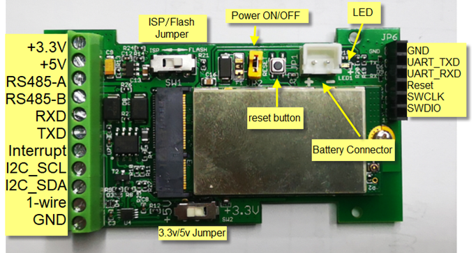
1.6 Pin mapping and power on
2. Operation Mode
2.1 How it works
Each LMDS120 is shipped with a worldwide unique set of OTAA keys. To use LMDS120 in a LoRaWAN network, user needs to input the OTAA keys in the LoRaWAN network server. So LMDS120 can join the LoRaWAN network and start to transmit sensor data.
2.2 Example to use for LoRaWAN network
Following is an example for how to join the TTN v3 LoRaWAN Network. Below is the network structure; we use the LG308 as a LoRaWAN gateway in this example.
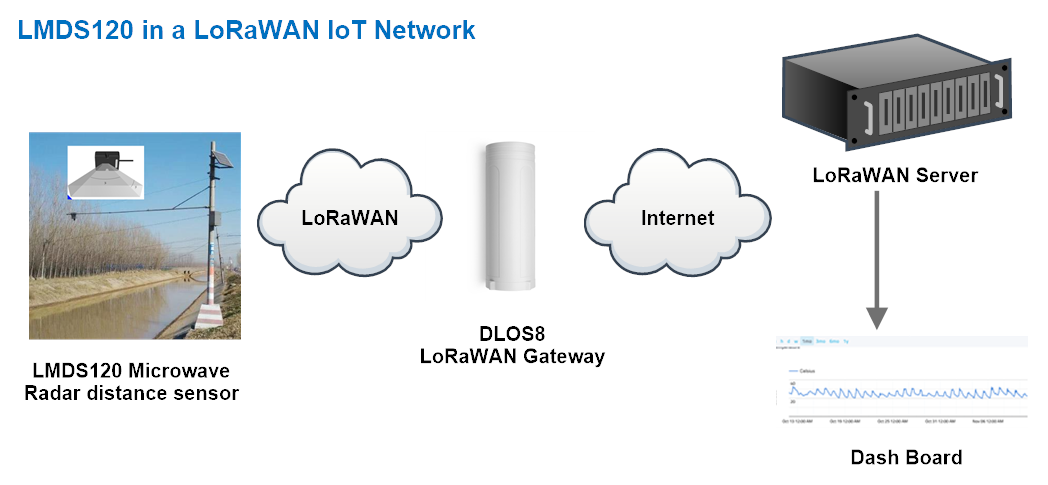
- In this user case, the LMDS120 is installed on top of river to detect the water level and send the level info to the LoRaWAN server. The LMDS120 will uplink different types of messages to the LoRaWAN server. See Uplink payload for detail.
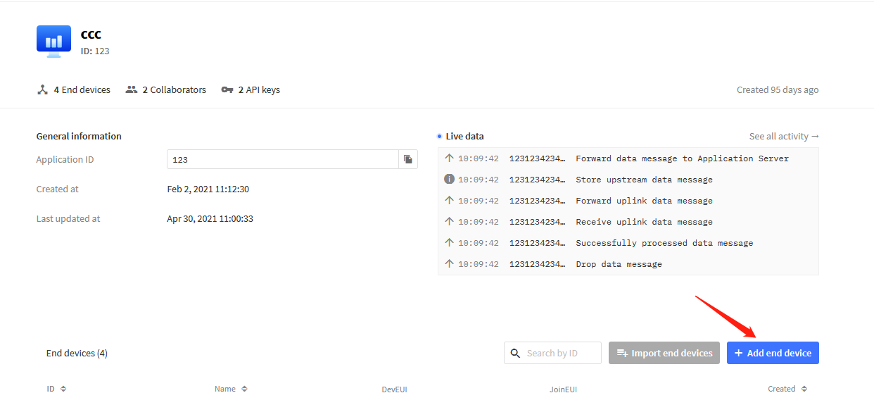
Assume the LoRaWAN Gateway DLOS8 is already set to connect to the TTN V3 network . We need to add the LMDS120 device in TTN V3:
Step 1: Create a device in TTN with the OTAA keys from LMDS120.
Each LMDS120 is shipped with a sticker with the default device keys, user can find this sticker in the box. it looks like below.
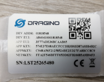
Users can enter these keys in the LoRaWAN Server portal. Below is the TTN V3 screenshot:
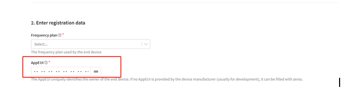
Add APP EUI in the application.
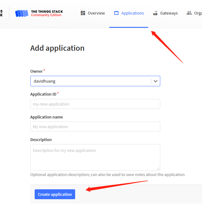
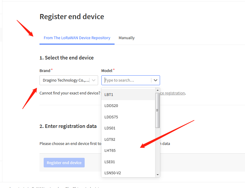
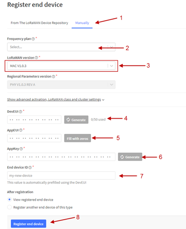
You can also choose to create the device manually.
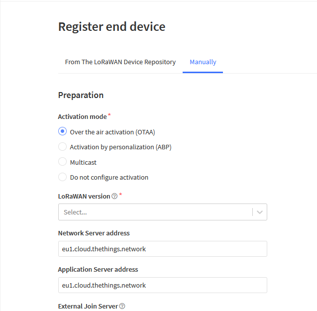
Add APP KEY and DEV EUI
Step 2: Power on LMDS120
Put a Jumper on JP2 to power on the device. ( The Switch must be in FLASH position).
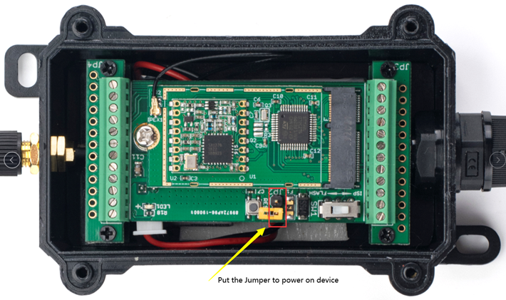
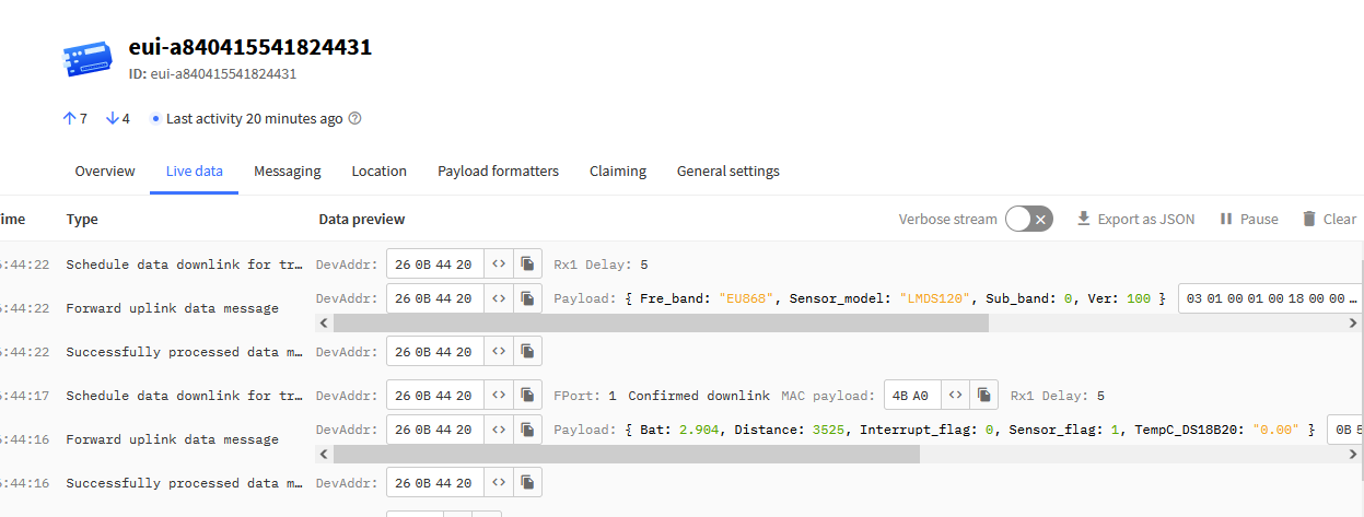
Put the jumper to power on LMDS120 and it will auto-join to the TTN V3 network. After join success, it will start to upload sensor data to TTN V3 and the user can see it in the panel.
2.3 Uplink Payload
Uplink payloads have two types:
- Distance Value: Use FPORT=2
- Other control commands: Use other FPORT fields.
The application server should parse the correct value based on FPORT settings.
2.3.1 Device Status, FPORT=5
Include device configure status. Once LMDS120 Joined the network, it will uplink this message to the server.
Users can also use the downlink command (0x26 01) to ask LMDS120 to resend Device Status.
| Device Status (FPORT=5) | |||||
| Size (bytes) | 1 | 2 | 1 | 1 | 2 |
| Value | Sensor Model | Firmware Version | Frequency Band | Sub-band | BAT |
- Sensor Model: For LMDS120, this value is 0x18
- Firmware Version: 0x0100, Means: v1.0.0 version
- Frequency Band:
*0x01: EU868
*0x02: US915
*0x03: IN865
*0x04: AU915
*0x05: KZ865
*0x06: RU864
*0x07: AS923
*0x08: AS923-1
*0x09: AS923-2
*0x0a: AS923-3
*0x0b: AS923-3
- Sub-Band:
- AU915 and US915:value 0x00 ~ 0x08
- CN470: value 0x0B ~ 0x0C
- Other Bands: Always 0x00
2.3.2 Distance, Uplink FPORT=2
LMDS120 will send this uplink after Device Status once join the LoRaWAN network successfully. And LMDS120 will:
- periodically send this uplink every 20 minute (TDC time), this interval can be changed.
- send this uplink while there is interrupt event.
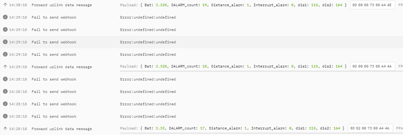
Uplink Payload totals 11 bytes.
| Distance Value, FPORT=2 | ||||
|---|---|---|---|---|
| Size(bytes) | 2 | 2 | 2 | 1 |
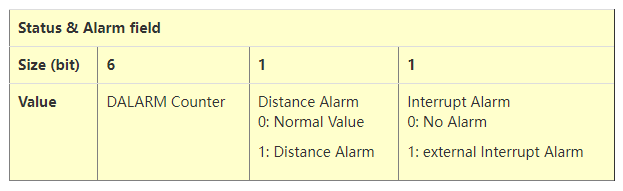
| Value | BAT | Object1 Distance | Object2 Distance | Status & Alarm |
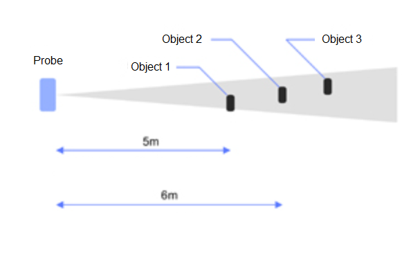
Object1 Distance:
Distance between sensor probe to the first object. (unit: cm)
For example, if the data you get from the register is 0x00 0x73, the distance between the sensor and the measured object is 0073(H) = 115 (D) = 115 cm.
Notice: There are two special values for object 1 distance:
0x0001: Probe not detected
0x0002: Reading Invalid (exceed the valid range of the probe)
Object2 Distance:
Distance between sensor probe to the second object. (unit: cm)
DALARM Counter : Alarm Counter.
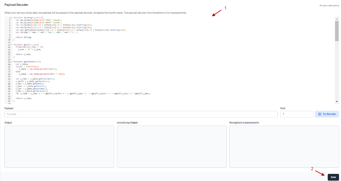
2.3.4 Decoder in TTN V3
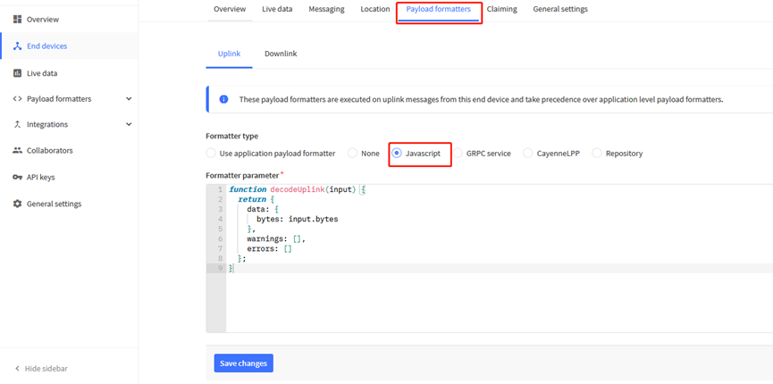
Please check the decoder from this link: https://github.com/dragino/dragino-end-node-decoder
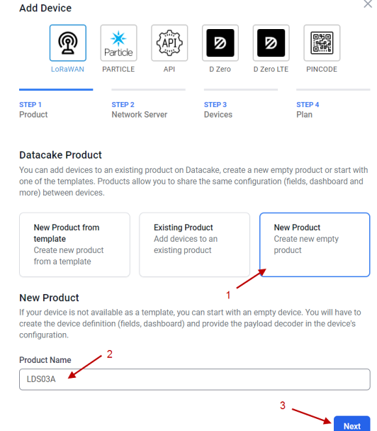
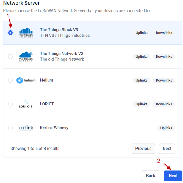
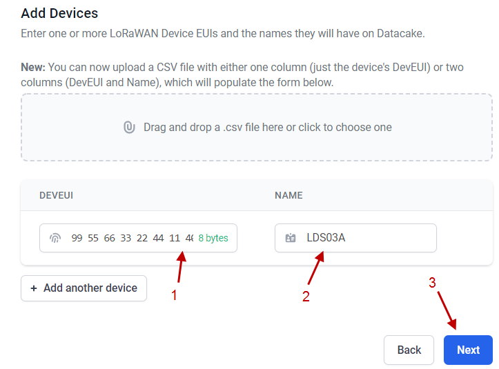
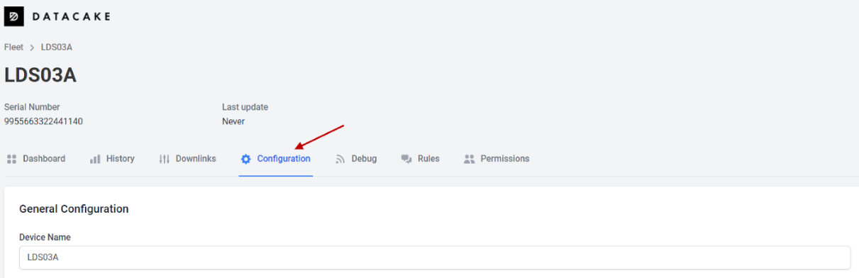
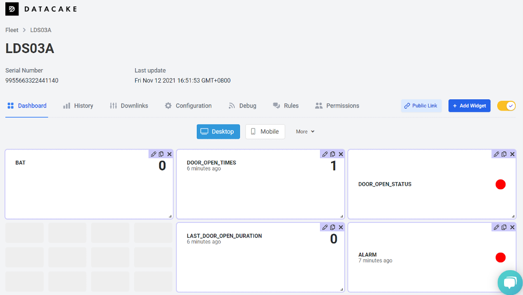
2.4 Show data on Datacake
Datacake IoT platform provides a human-friendly interface to show the sensor data, once we have sensor data in TTN V3, we can use Datacake to connect to TTN V3 and see the data in Datacake. Below are the steps:
Step 1: Link TTNv3 to DATACAKE
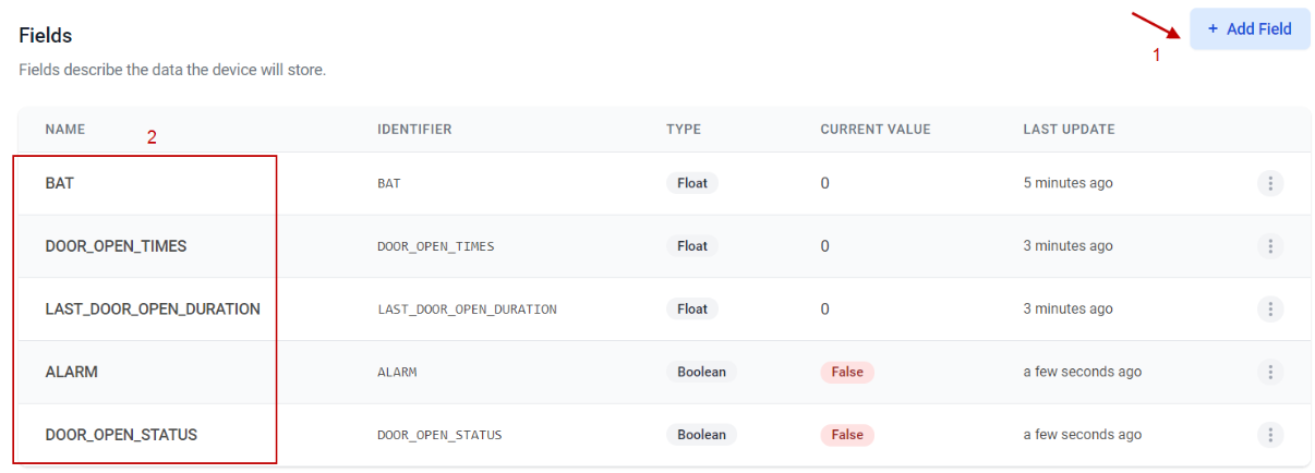
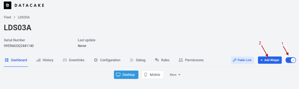
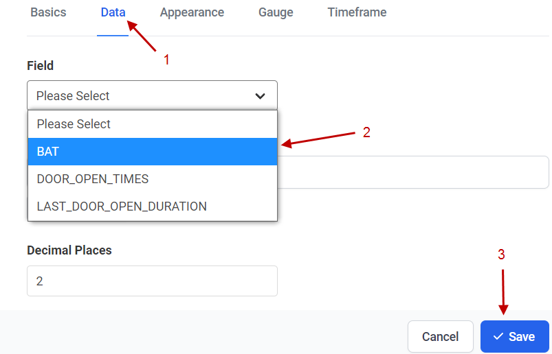
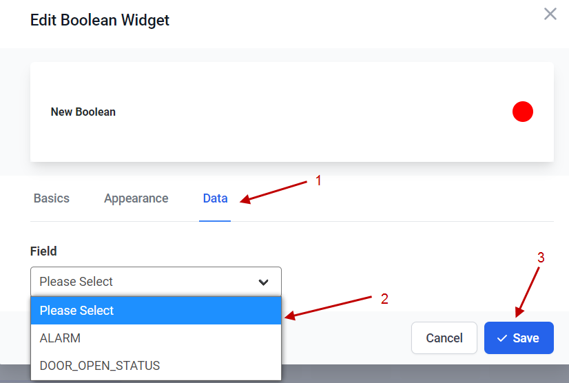
Step 2: Configure LMDS200 in Datacake
3. Configure LMDS200 via AT Command or LoRaWAN Downlink
Use can configure LMDS200 via AT Command or LoRaWAN Downlink.
AT Command Connection: See FAQ.
LoRaWAN Downlink instruction for different platforms: IoT LoRaWAN Server
There are two kinds of commands to configure LMDS200, they are:
General Commands.
These commands are to configure:
General system settings like: uplink interval.
LoRaWAN protocol & radio related command.
They are same for all Dragino Device which support DLWS-005 LoRaWAN Stack(Note**). These commands can be found on the wiki: End Device AT Commands and Downlink Command
Commands special design for LMDS200
These commands only valid for LMDS200, as below:
3.1 Set Transmit Interval Time(0x01)
Feature: Change LoRaWAN End Node Transmit Interval.
AT Command: AT+TDC
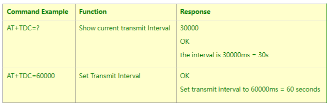
Downlink Command: 0x01
Format: Command Code (0x01) followed by 3 bytes time value.
If the downlink payload=0100003C, it means set the END Node's Transmit Interval to 0x00003C=60(S), while type code is 01.
- Example 1: Downlink Payload: 0100001E // Set Transmit Interval (TDC) = 30 seconds
- Example 2: Downlink Payload: 0100003C // Set Transmit Interval (TDC) = 60 seconds
3.2 Set Alarm Transmit Interval Time(0x0D)
Feature: Change LoRaWAN End Node Alarm Transmit Interval. Default Value: 1 minute
AT Command: AT+ATDC
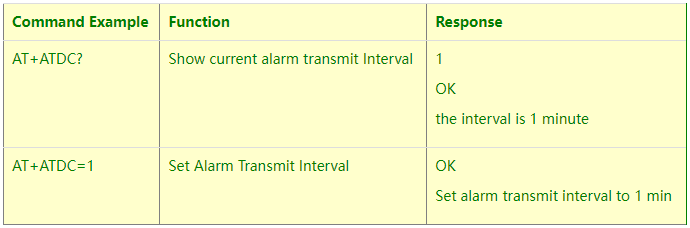
Downlink Command: 0x0D
Format: Command Code (0x0D) followed by 1 byte for time value.
If the downlink payload=0D02, it means set the END Node's Alarm Transmit Interval to 2 minutes, while type code is 0D.
3.3 Set Alarm Distance (0xA2)
LMDS02 supports Alarm Feature, when LMDS02 detect the distance exceed the alarm settings, LMDS02 will Enter Alarm Mode and use the ATDC interval (default is 1 minute) to uplink Distance value. Alarm mode will last for 60 uplinks (default 1 hour) and can be close by downlink command 0xA300.
Note: Alarm mode only valid for the Distance 1(the Closest Object)
User can set Alarm Distance to enable/disable Alarm Mode.
AT+ALARMC=AABBCCDD
- AABB: Hex value for Alarm low threshold, CCDD: Hex value for Alarm high threshold
- When 0xAABB=0, and 0xCCDD≠0, Alarm trigger when higher than max
- When 0xAABB≠0, and 0xCCDD =0xFFFF, Alarm trigger when lower than min
- When 0xAABB≠0 and 0xCCDD≠0, Alarm trigger when higher than max or lower than min
Example:
AT+ALARMC=006400C8 // Alarm when < 100 or higher than 200.
- Downlink Payload:
0x(A2 00 01 00 00) // Same as AT+ALARMC=00010000
3.4 Enter/Exit Alarm Mode (0xA3)
Feature: Enter/Exit Alarm mode:
AT Command: AT+ALARM=0(Exit Alarm Mode or AT+ALARM=1 (Enter Alarm Mode)
Downlink Command:
0xA3 00 // Exit Alarm Mode.
0xA3 01 // Enter Alarm Mode. Enter Alarm mode will use ATDC interval in the next 59 uplinks.
3.5 Set Interrupt Mode(0x06)
Feature, Set Interrupt mode for GPIO_EXIT.
Downlink Command: AT+INTMOD
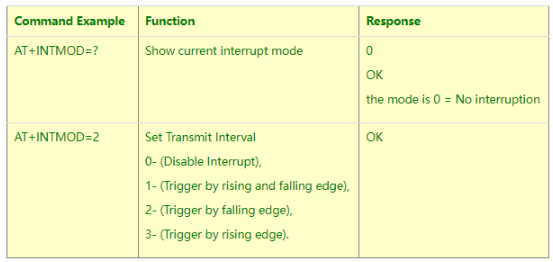
Downlink Command: 0x06
Format: Command Code (0x06) followed by 3 bytes.
This means that the interrupt mode of the end node is set to 0x000003=3 (rising edge trigger), and the type code is 06.
Example 1: Downlink Payload: 06000000 // Turn off interrupt mode
Example 2: Downlink Payload: 06000003 // Set the interrupt mode to rising edge trigger
4. Battery & how to replace
4.1 Battery Type
LMDS200 is equipped with a 8500mAH ER26500 Li-SOCI2 battery. The battery is un-rechargeable battery with low discharge rate targeting for 8~10 years use. This type of battery is commonly used in IoT target for long-term running, such as water meter.
The discharge curve is not linear so can't simply use percentage to show the battery level. Below is the battery performance.
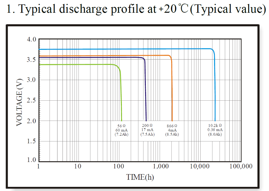
Minimum Working Voltage for the LMDS200:
LMDS200: 2.45v ~ 3.6v
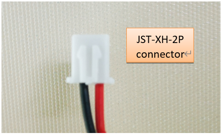
4.2 Replace Battery
Any battery with range 2.45 ~ 3.6v can be a replacement. We recommend to use Li-SOCl2 Battery.
And make sure the positive and negative pins match.
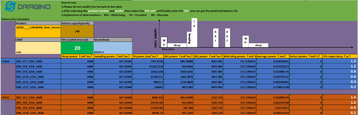
4.3 Power Consumption Analyze
Dragino Battery powered product are all runs in Low Power mode. We have an update battery calculator which base on the measurement of the real device. User can use this calculator to check the battery life and calculate the battery life if want to use different transmit interval.
Instruction to use as below:
Step 1: Downlink the up-to-date DRAGINO_Battery_Life_Prediction_Table.xlsx from:
https://www.dragino.com/downloads/index.php?dir=LoRa_End_Node/Battery_Analyze/
Step 2: Open it and choose
- Product Model
- Uplink Interval
- Working Mode
And the Life expectation in difference case will be shown on the right.
The battery related documents as below:
4.3.1 Battery Note
The Li-SICO battery is designed for small current / long period application. It is not good to use a high current, short period transmit method. The recommended minimum period for use of this battery is 5 minutes. If you use a shorter period time to transmit LoRa, then the battery life may be decreased.
4.3.2 Replace the battery
You can change the battery in the LMDS200.The type of battery is not limited as long as the output is between 3v to 3.6v.
The default battery pack of LMDS200 includes a ER26500 plus super capacitor. If user can't find this pack locally, they can find ER26500 or equivalence, which will also work in most case. The SPC can enlarge the battery life for high frequency use (update period below 5 minutes).
5. FAQ
5.1 How to use AT Command to configure LMDS200
LMDS200 UART connection photo
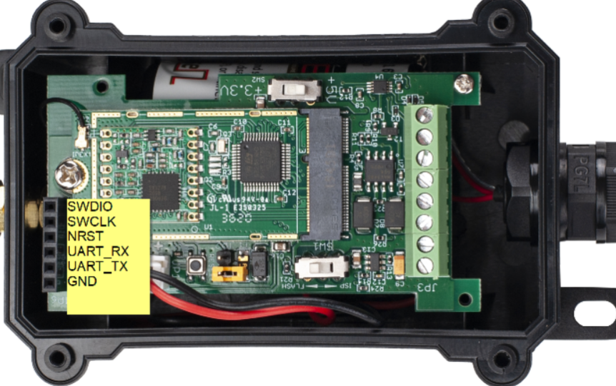
LMDS200 supports AT Command set. User can use a USB to TTL adapter plus the 3.5mm Program Cable to connect to LMDS200 to use AT command, as below.
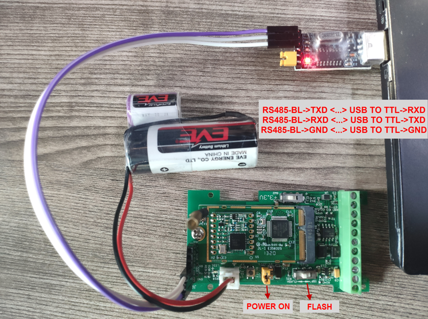
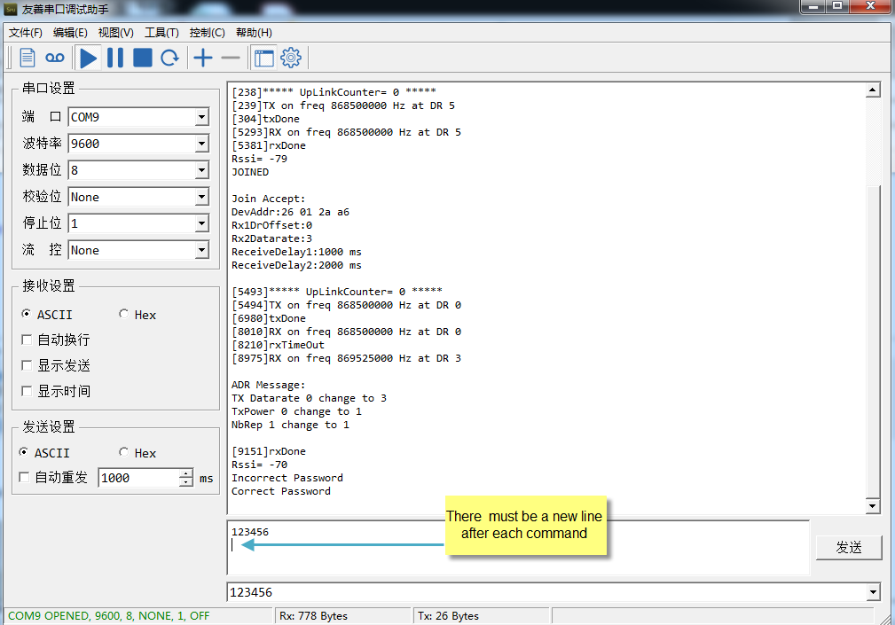
In the PC, you need to set the serial baud rate to 9600 to access the serial console for LMDS200. LMDS200 will output system info once power on as below:
5.2 How to upgrade the firmware?
A new firmware might be available for:
Support new features
For bug fix
Change LoRaWAN bands.
Instruction for how to upgrade: http://wiki.dragino.com/xwiki/bin/view/Main/Firmware%20Upgrade%20Instruction%20for%20STM32%20base%20products/#H2.HardwareUpgradeMethodSupportList
5.3 How to change the LoRa Frequency Bands/Region
You can follow the instructions for how to upgrade image.
When downloading the images, choose the required image file for download.
6. Trouble Shooting
6.1 AT Command input doesn't work
In the case if user can see the console output but can't type input to the device. Please check if you already include the ENTER while sending out the command. Some serial tool doesn't send ENTER while press the send key, user need to add ENTER in their string.
7. Order Info
Part Number : LMDS200-XX
XX: The default frequency band
- AS923 : LoRaWAN AS923 band
- AU915 : LoRaWAN AU915 band
- EU433 : LoRaWAN EU433 band
- EU868 : LoRaWAN EU868 band
- KR920 : LoRaWAN KR920 band
- US915 : LoRaWAN US915 band
- IN865 : LoRaWAN IN865 band
- CN470 : LoRaWAN CN470 band
8. Packing Info
Package Includes:
LMDS200 LoRaWAN Microwave Radar Distance Sensor x 1
9. Support
- Support is provided Monday to Friday, from 09:00 to 18:00 GMT+8. Due to different timezones we cannot offer live support. However, your questions will be answered as soon as possible in the before-mentioned schedule.
- Provide as much information as possible regarding your enquiry (product models, accurately describe your problem and steps to replicate it etc) and send a mail to support@dragino.com.