Table of Contents:
1. Introduction
1.1 What is LHT52 Temperature & Humidity Sensor
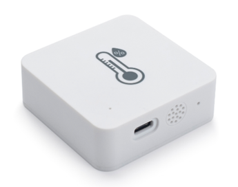
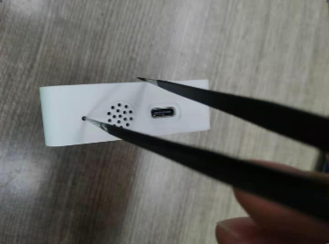
The Dragino LHT52 Temperature & Humidity sensor is a Long Range LoRaWAN Sensor. It includes a built-in Temperature & Humidity sensor and has a USB Type-C sensor connector to connect to external sensors such as external Temperature Sensor.
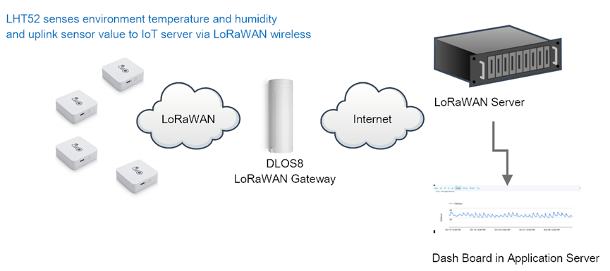
LHT52 senses environment temperature and humidity and send these values via long-range wireless LoRaWAN protocol. It targets professional wireless sensor network applications such as food service, smart metering, smart cities, building automation, and so on.
LHT52 supports 2 x AAA batteries and works for a long time up to several years. Use can replace the batteries easily after they are finished.
LHT52 is fully compatible with LoRaWAN v1.0.3 protocol, it can work with standard LoRaWAN gateway.
LHT52 supports Datalog feature to make sure users won’t miss sensor data. It records sensor value for every uplink. These values can be retrieved by LoRaWAN server via downlink command.
LHT52 supports temperature alarm feature. It can uplink alarm in a short interval while temperature exceeds preset limits.
*Battery life depends how often to send data, please see battery analyzer.
1.2 Features
- Wall Attachable.
- LoRaWAN v1.0.3 Class A protocol.
- Built-in Temperature & Humidity sensor
- Optional External Probe
- Frequency Bands: CN470/EU433/KR920/US915/EU868/AS923/AU915
- AT Commands to change parameters
- Remote configure parameters via LoRaWAN Downlink
- Firmware upgradable via program port
- Support 2 x AAA LR03 batteries.
- Datalog feature
- IP Rating: IP52
1.3 Specification
Built-in Temperature Sensor:
- Resolution: 0.01 °C
- Accuracy Tolerance: Typ ±0.3 °C
- Long Term Drift: < 0.02 °C/yr
- Operating Range: -20 ~ 50 °C
Built-in Humidity Sensor:
- Resolution: 0.1 %RH
- Accuracy Tolerance: Typ ±3 %RH
- Long Term Drift: < 0.02 °C/yr
- Operating Range: 0 ~ 99.0 %RH(no Dew)
1.4 Power Consumption
LHT52 (without external sensor): Idle: 5uA, Transmit: max 110mA
LHT52 + External Temperature Probe (AS-01): Idle: 6uA, Transmit: max 110mA.
1.5 Storage & Operation Temperature
-20°C to +50°C
1.6 Applications
- Smart Buildings & Home Automation
- Logistics and Supply Chain Management
- Smart Metering
- Smart Agriculture
- Smart Cities
- Smart Factory
2. Operation Mode
2.1 How it work?
Each LHT52 is shipped with a worldwide unique set of LoRaWAN OTAA keys. To use LHT52 in a LoRaWAN network, user needs to input the OTAA keys in LoRaWAN network server. After this, if LHT52 is under this LoRaWAN network coverage, LHT52 can join the LoRaWAN network and start to transmit sensor data. The default period for each uplink is 20 minutes.
2.2 How to Activate LHT52?
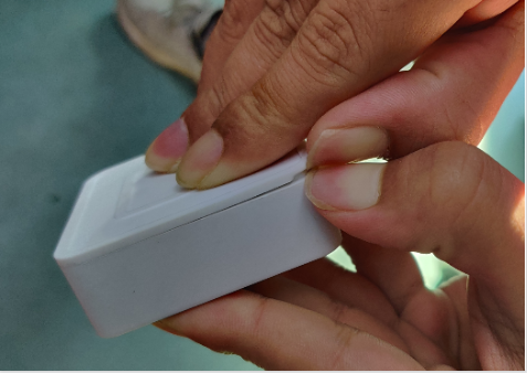
1. Open enclosure from below position.
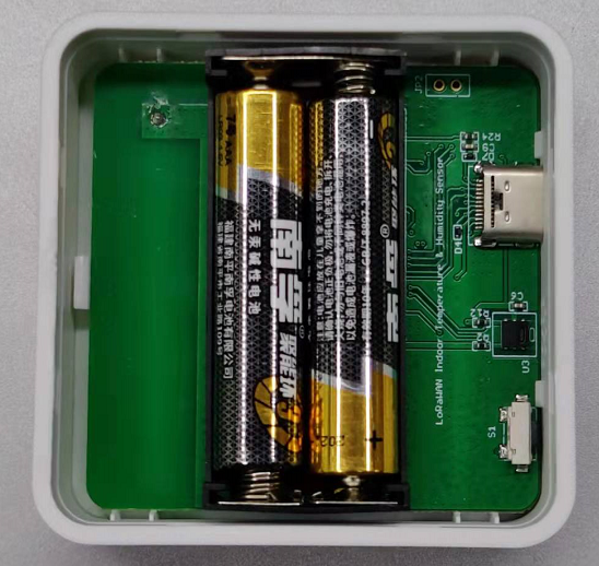
2. Insert 2 x AAA LR03 batteries.
3. Press the reset button to activate device.
User can check LED Status to know the working state of LHT52.
2.3 Example to join LoRaWAN network
This section shows an example for how to join the TheThingsNetwork LoRaWAN IoT server. Usages with other LoRaWAN IoT servers are of similar procedure.
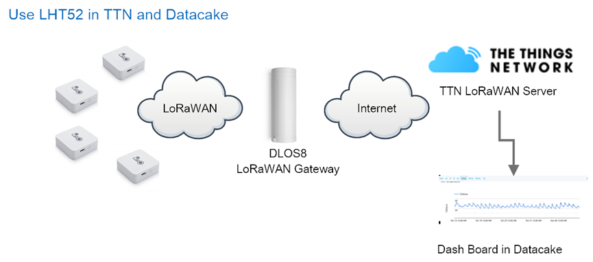
Assume the DLOS8 is already set to connect to TTN V3 network . We need to add the LHT52 device in TTN V3 portal.
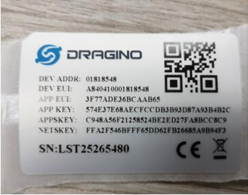
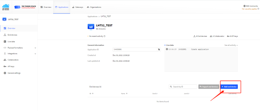
Step 1: Create a device in TTN V3 with the OTAA keys from LHT52.
Each LHT52 is shipped with a sticker with the default DEV EUI as below:
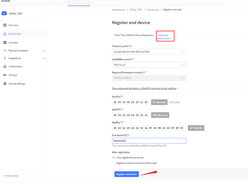
Enter these keys in the LoRaWAN Server portal. Below is TTN V3 screen shot:
Add APP EUI in the application.
choose to create the device manually.
Add APP KEY and DEV EUI
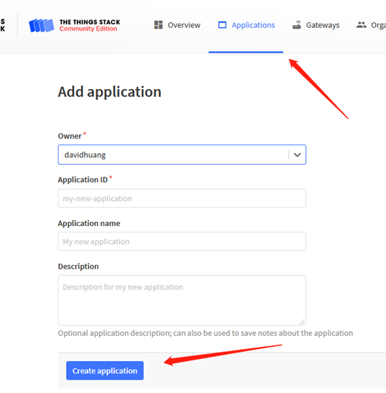
Default mode OTAA
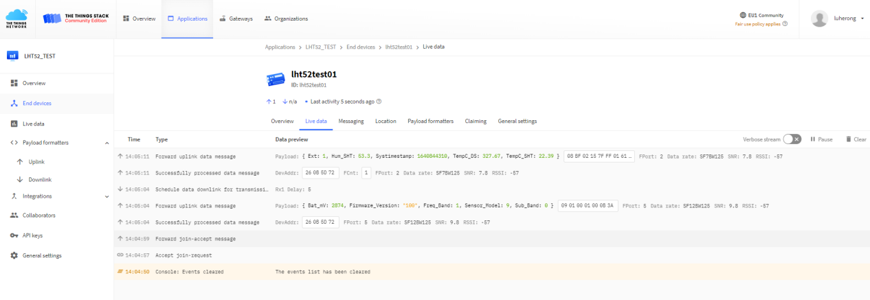
Step 2: Use ACT button to activate LHT52 and it will auto join to the TTN V3 network. After join success, it will start to upload sensor data to TTN V3 and user can see in the panel.
2.4 Uplink Payload
Uplink payloads include two types: Valid Sensor Value and other status / control command.
- Valid Sensor Value: Use FPORT=2
- Other control command: Use FPORT other than 2.
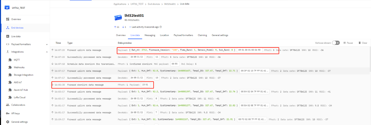
2.4.1 Uplink FPORT=5, Device Status
Uplink the device configures with FPORT=5. Once LHT52 Joined the network, it will uplink this message to the server. After first uplink, LHT52 will uplink Device Status every 12 hours.
| Size (bytes) | 1 | 2 | 1 | 1 | 2 |
|---|---|---|---|---|---|
| Value | Sensor Model | Firmware Version | Frequency Band | Sub-band | BAT |
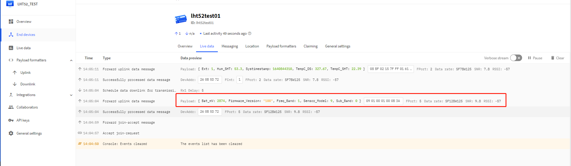
Example Payload (FPort=5): 
Sensor Model: For LHT52, this value is 0x09.
Firmware Version: 0x0100, Means: v1.0.0 version.
Frequency Band:
*0x01: EU868
*0x02: US915
*0x03: IN865
*0x04: AU915
*0x05: KZ865
*0x06: RU864
*0x07: AS923
*0x08: AS923-1
*0x09: AS923-2
*0x0a: AS923-3
Sub-Band: value 0x00 ~ 0x08(only for CN470, AU915,US915. Others are0x00)
BAT: shows the battery voltage for LHT52.
Ex1: 0x0B3A = 2874mV
Use can also get the Device Status uplink through the downlink command:
Downlink: 0x2301
2.4.2 Uplink FPORT=2, Real time sensor value
LHT52 will send this uplink after Device Status uplink once join LoRaWAN network successfully. And it will periodically send this uplink. Default interval is 20 minutes and can be changed.
Uplink uses FPORT=2 and every 20 minutes send one uplink by default.
Size(bytes) | 2 | 2 | 2 | 1 | 4 |
|---|---|---|---|---|---|
Value | Ext # |
Temperature:
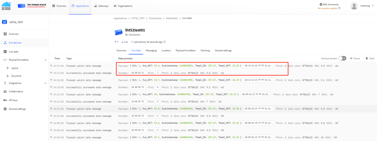
Example Payload (FPort=2):
08 CD 02 20 7F FF 01 61 CD 4E DD
Temperature & External Temperature:
- Example1: 0x08CD/100=22.53℃
- Example2: (0xF5C6-65536)/100=-26.18℃
Humidity:
- Humidity: 0x0220/10=54.4%
Extension #
Bytes for External Sensor:
| EXT # Value | External Sensor Probe |
|---|---|
| 0x01 | Sensor AS-01, Temperature |
2.4.3 Uplink FPORT=3, Datalog sensor value
LHT52 stores sensor value and user can retrieve these history value via downlink command. The Datalog sensor value are sent via FPORT=3.
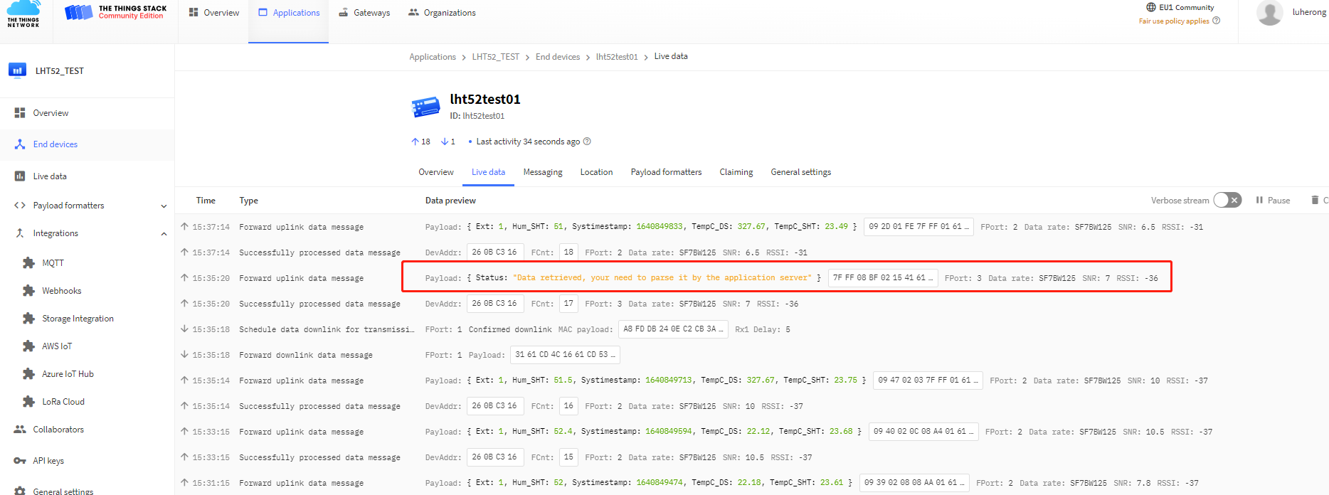
- Each data entry is 11 bytes, to save airtime and battery, LHT52 will send max bytes according to the current DR and Frequency bands.
For example, in US915 band, the max payload for different DR is:
- DR0: max is 11 bytes so one entry of data
- DR1: max is 53 bytes so devices will upload 4 entries of data (total 44 bytes)
- DR2: total payload includes 11 entries of data
- DR3: total payload includes 22 entries of data.
Notice: LHT52 will save 178 set of history data, If device doesn't have any data in the polling time. Device will uplink 11 bytes of 0.
See more info about the Datalog feature.
2.4.4 Uplink FPORT=4, DS18B20 ID
User can get external DS18B20 ID through the downlink command.
Downlink:0x2302
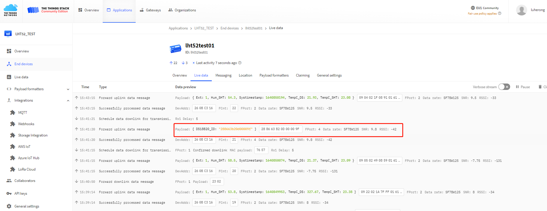
Example Payload (FPort=4):
28 86 63 B2 00 00 00 9F
The External DS18B20 ID is 0x28 86 63 B2 00 00 00 9F
2.4.5 Decoder in TTN V3
In LoRaWAN protocol, the uplink payload is HEX format, user need to add a payload formatter/decoder in LoRaWAN Server to get human friendly string.
In TTN , add formatter as below:
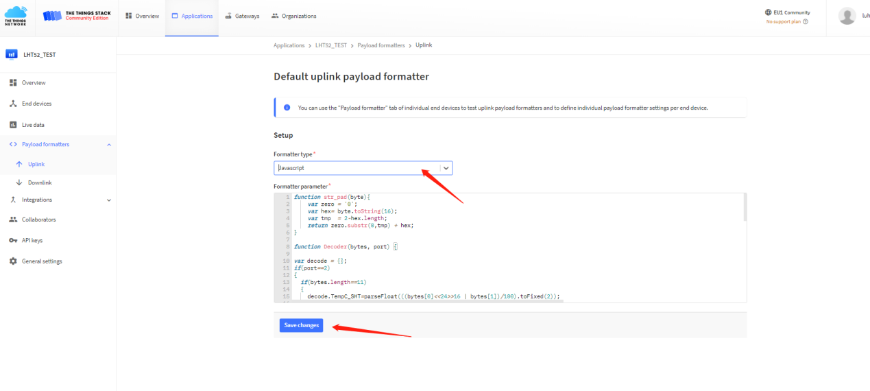
Please check the decoder from this link:
https://www.dragino.com/downloads/index.php?dir=LoRa_End_Node/LHT52/Decoder/
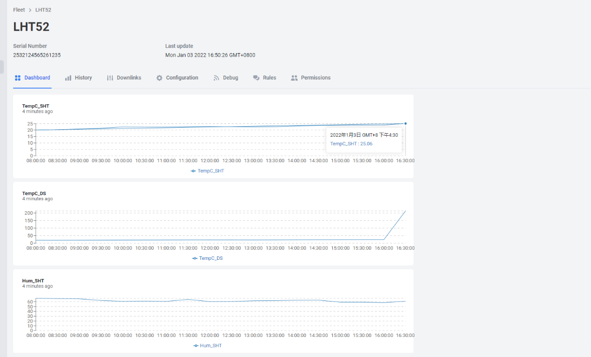
2.5 Show data on Datacake
Datacake IoT platform provides a human friendly interface to show the sensor data in charts, once we have sensor data in TTN V3, we can use Datacake to connect to TTN V3 and see the data in Datacake. Below are the steps:
Step 1: Be sure that your device is programmed and properly connected to the LoRaWAN network.
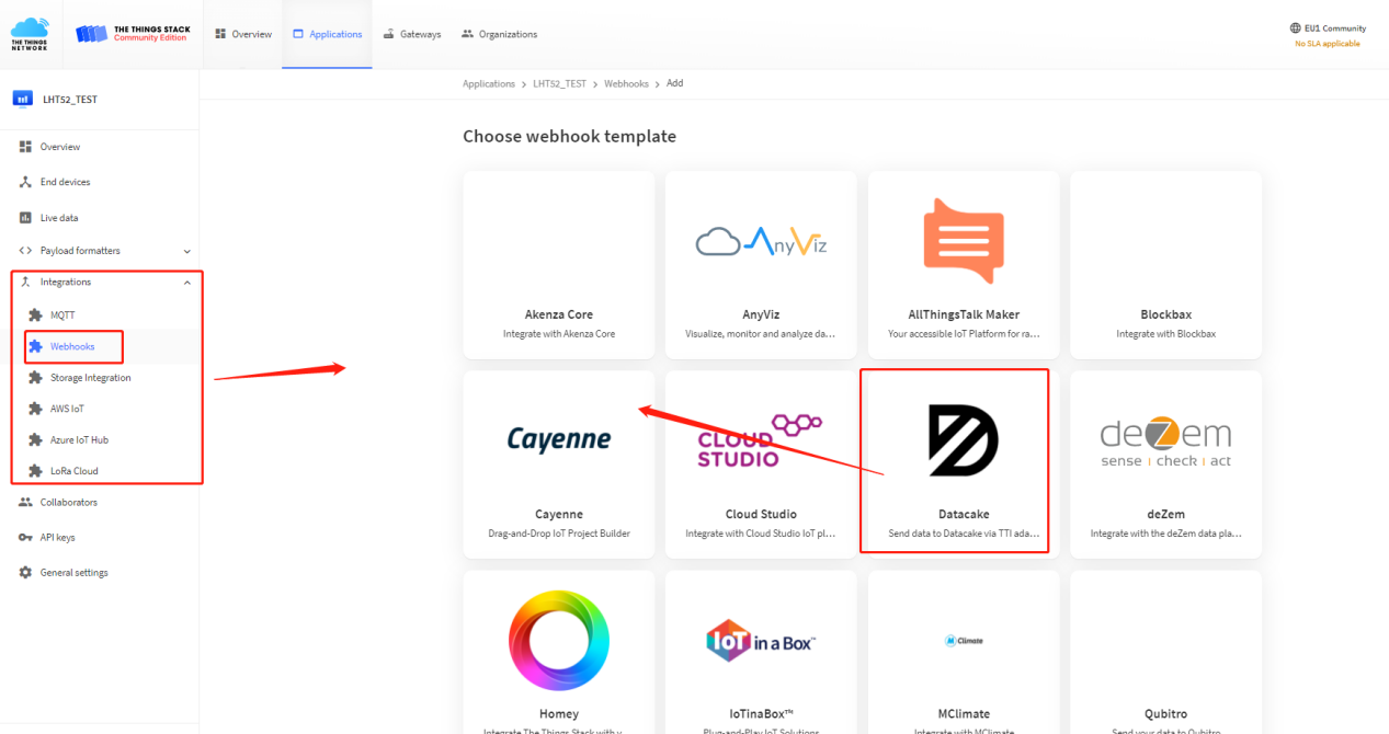
Step 2: Configure your Application to forward data to Datacake you will need to add integration. Go to TTN V3 Console --> Applications --> Integrations --> Add Integrations.
- Add Datacake:
2. Select default key as Access Key:
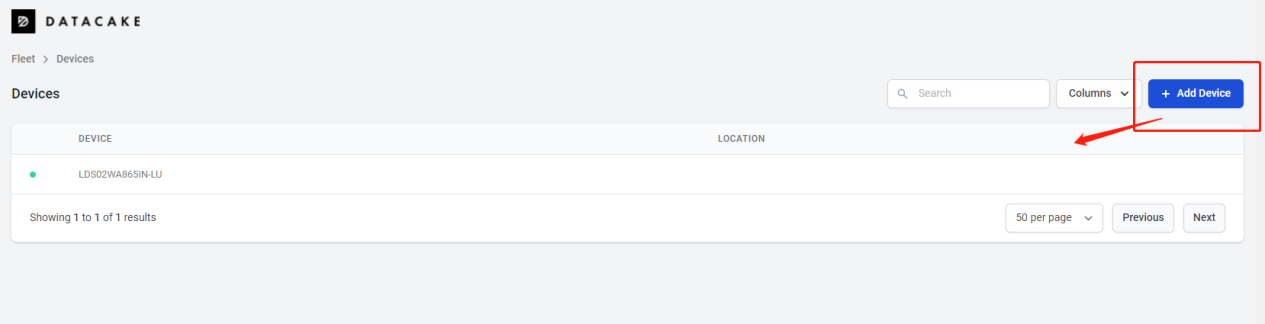
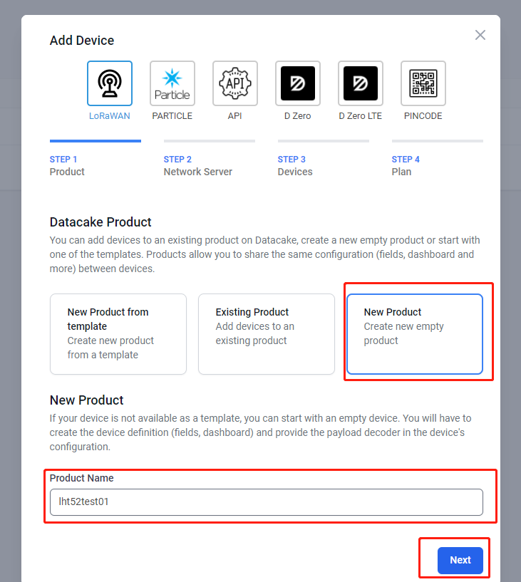
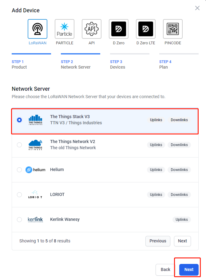
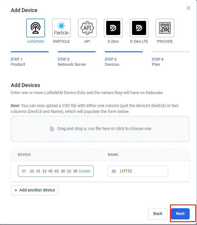
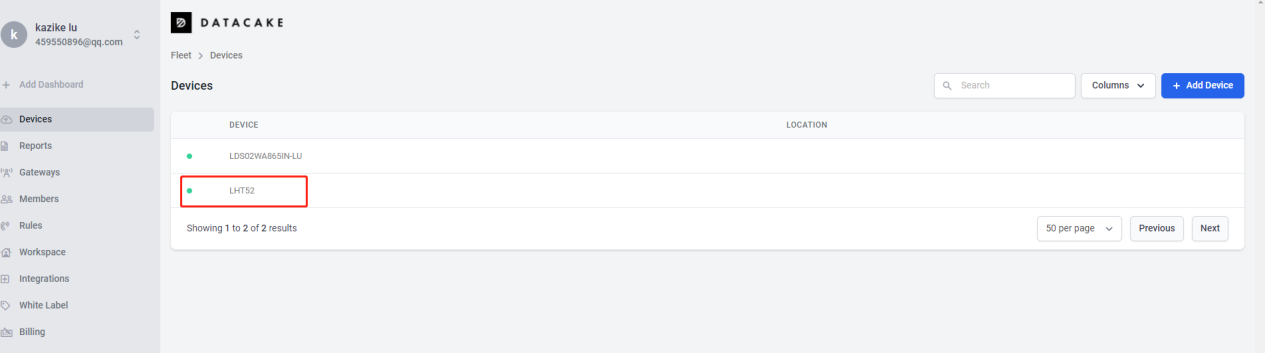
3. In Datacake console (https://datacake.co/) , add LHT52:
Please refer to the figure below
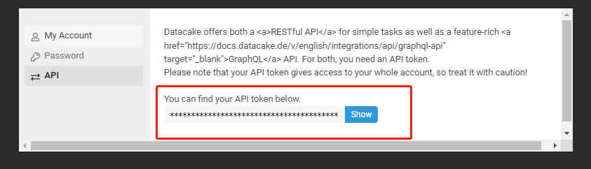
Log in to DATACAKE, copy the API under the account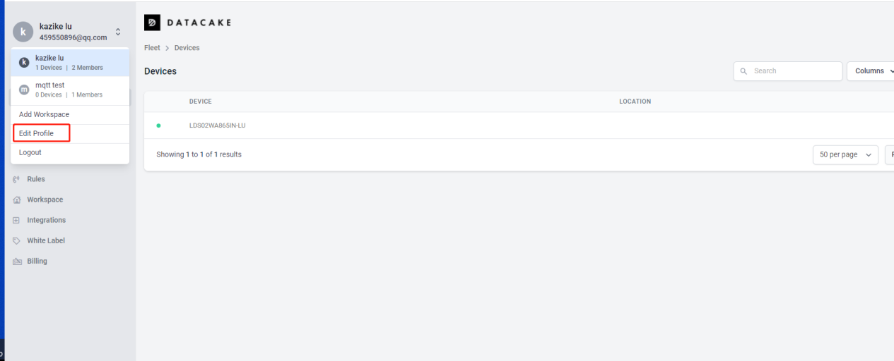
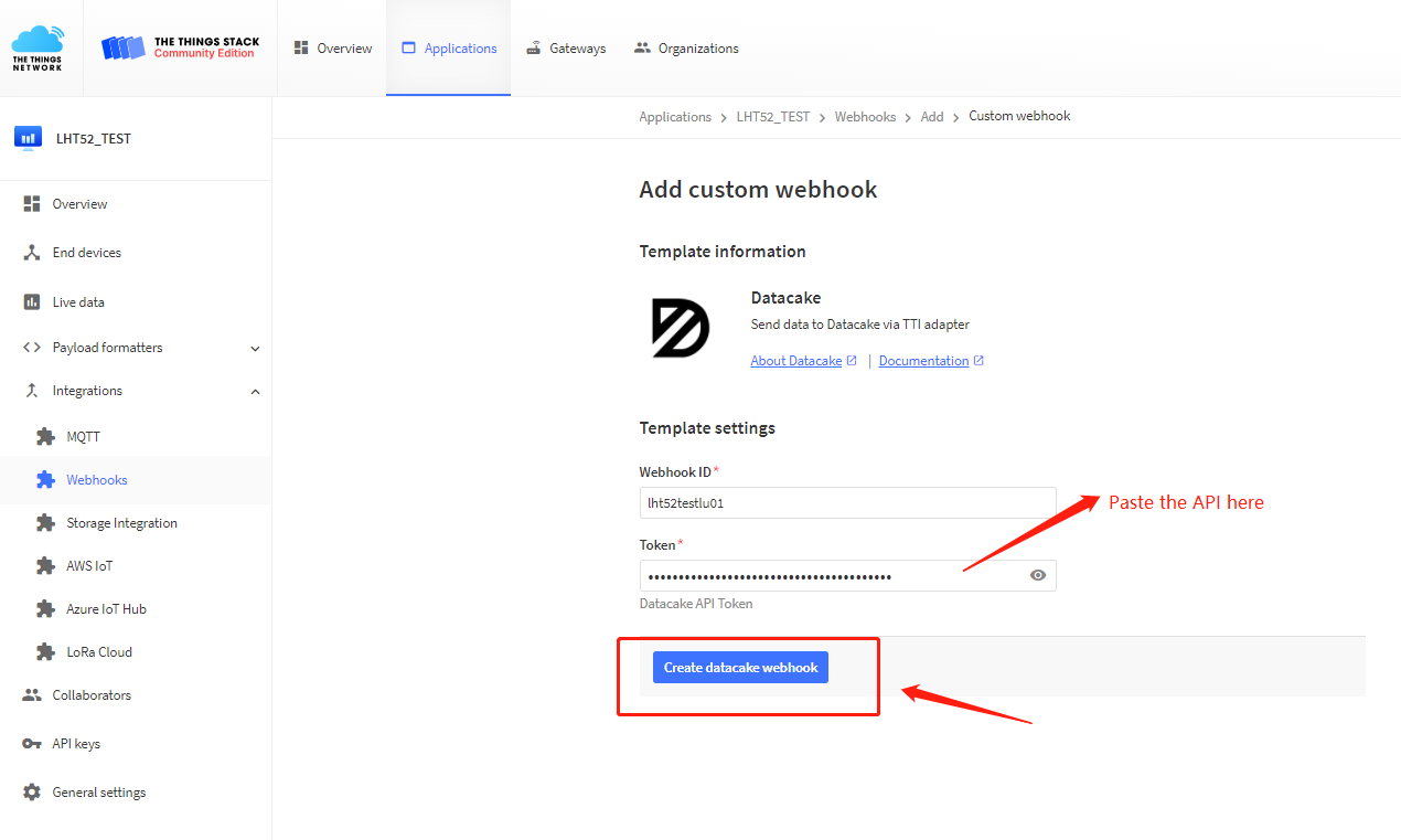
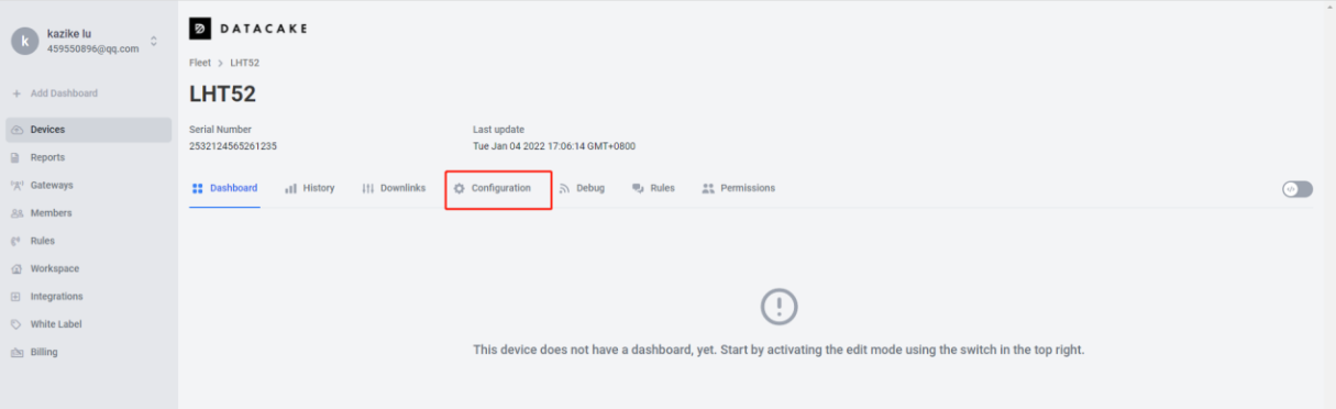
Copy and paste the TTN decoder here and save
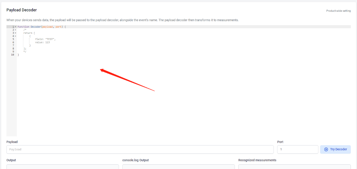
Visual widgets please read the DATACAKE documentation
2.6 Datalog Feature
When user want to retrieve sensor value, he can send a poll command from the IoT platform to ask sensor to send value in the required time slot.
2.6.1 Unix TimeStamp
Unix TimeStamp shows the sampling time of uplink payload. format base on
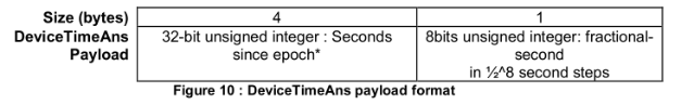
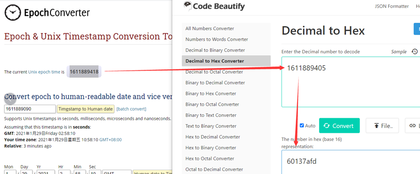
User can get this time from link: https://www.epochconverter.com/ :
For example: if the Unix Timestamp we got is hex 0x60137afd, we can convert it to Decimal: 1611889405. and then convert to the time: 2021 – Jan -- 29 Friday 03:03:25 (GMT)
2.6.2 Poll sensor value
User can poll sensor value based on timestamps from the server. Below is the downlink command.
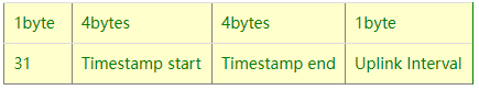
Timestamp start and Timestamp end use Unix TimeStamp format as mentioned above. Devices will reply with all data log during this time period, use the uplink interval.
For example, downlink command 
Is to check 2020/12/1 07:40:00 to 2020/12/1 08:40:00's data
Uplink Internal =5s,means LHT52 will send one packet every 5s. range 5~255s.
2.6.3 Datalog Uplink payload
See Uplink FPORT=3, Datalog sensor value
2.7 Alarm Mode
When device is in Alarm mode, it will check the built-in sensor temperature in a short interval. If the temperature exceeds the pre-configure range, it will send an uplink immediately.
The alarm mode can be modified by AT command or downlink, Alarm mode is disabled by default.
If you need to enable the Alarm mode, please refer to the following
Note: Alarm mode will increase the power consumption, we recommend extending the normal uplink time (20 minutes default) when enable this feature.
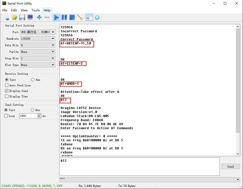
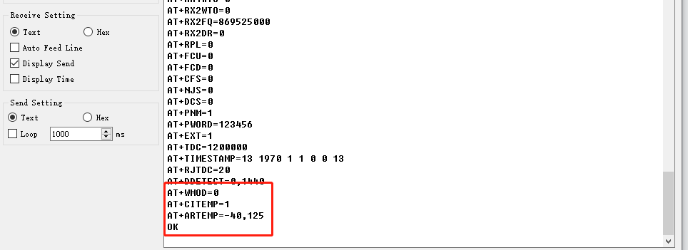
AT Commands for Alarm mode:
AT+WMOD=1: Enable/Disable Alarm Mode. (0:Disable, 1: Enable),need to reset the node to take effect
AT+CITEMP=1: The interval to check temperature for Alarm. (Unit: minute)
AT+ARTEMP=-40,125: Set the normal temperature range from -40°C to 125°C
Suppose you want to set the normal temperature from 15°C to 50°C, and turn on the alarm mode, and check the temperature every 2 minutes. Please refer to the following

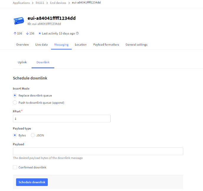
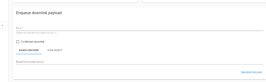
Modification via downlink,Take TTN_V3 as an example(downlink commands, please refer to the downlink command set for details)
In order to ensure that the node is indeed modified by downlink, I reset the node to factory settings first.
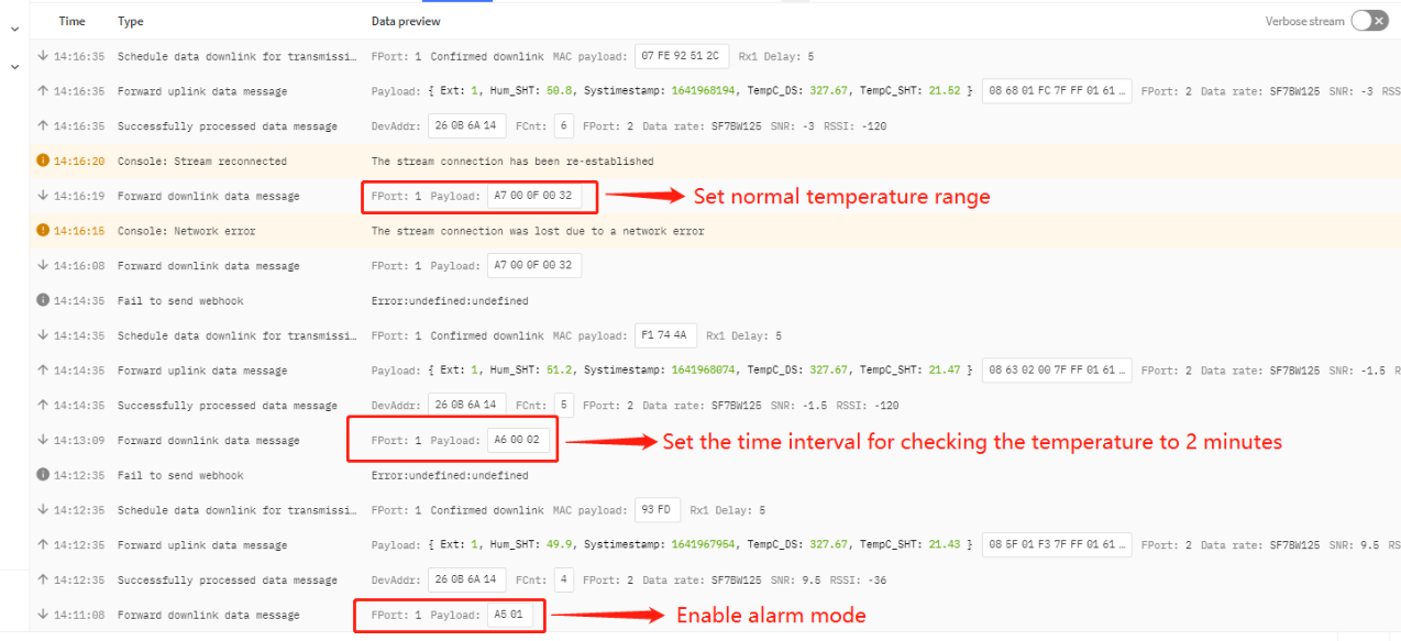

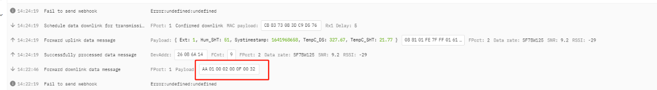
Or use a downlink directly: AA010002000F0032 (See command info)
2.8 LED Indicator
The LHT52 has a triple color LED which for easy showing different stage.
In a normal working state:
- When the node is restarted, GREEN, RED and BLUE are sequentially lit.
- During OTAA Join:
- For each Join Request uplink: the GREEN LED will blink once.
- Once Join Successful: the GREEN LED will be solid on for 5 seconds.
- After joined, for each uplink, the BLUE LED or GREEN LED will blink once.
- BLUE LED when external sensor is connected
- GREEN LED when external sensor is not connected
- For each success downlink, the PURPLE LED will blink once
In AT Command Mode:
If user use console cable to send AT Command to LHT52, the RED LED will always on until:
- Power off/on LHT52
- Press reset button of LHT52.
- Send an AT Command: AT+CLPM=1
2.9 Button
Press the button LHT52 will reset and join network again.
3. Configure LHT52 via AT command or LoRaWAN downlink
Use can configure LHT52 via AT Command or LoRaWAN Downlink.
AT Command Connection: See FAQ.
LoRaWAN Downlink instruction for different platforms: IoT LoRaWAN Server
There are two kinds of commands to configure LHT52, they are:
* General Commands.
These commands are to configure:
General system settings like: uplink interval.
LoRaWAN protocol & radio-related commands.
They are the same for all Dragino Devices which supports DLWS-005 LoRaWAN Stack(Note**). These commands can be found on the wiki: End Device Downlink Command
* Commands special design for LHT52
These commands are only valid for LHT52, as below:
3.1 Set Transmit Interval Time
| Command Example | Function | Response | Downlink |
|---|---|---|---|
| AT+TDC=? | View current TDC time | 1200000 OK | Default 1200000(ms) |
| AT+TDC=300000 | Set TDC time | OK | 0X0100012C: 01:fixed command 00012C:0X00012C=300(seconds) |
| ATZ | Reset node | 0x04FF | |
| AT+FDR | Restore factory settings | 0X04FE | |
| AT+CFM=? | View the current confirmation mode status | 0 OK | Default 0 |
| AT+CFM=1 | Turn on confirmation mode | OK | 0x0500:close 0x0501:open 05:fixed command |
| AT+CHE=? | View the current sub-band select 0-7, the default is 0 | 0 OK | Default 0 |
| AT+CHE=2 | Set subband to 2 (CN470,US915,AU915) | Attention:Take effect after ATZ OK
| 0X0702: 07:fixed command 02:Select subband 2 |
| AT+WMOD=? | View the current alarm mode status | 0 OK | Default 0 |
| AT+WMOD=1 | Turn on alarm mode | Attention:Take effect after ATZ OK
| 0xA501:open 0XA500:close A5:fixed command
|
| AT+CITEMP=? | View the current temperature detection time interval | 1 OK | Default 1(min) |
| AT+CITEMP=2 | Set the temperature detection time interval to 2min | OK | 0XA70002 A7:fixed command 0002:0X0002=2(min) |
| AT+NJM=? | Check the current network connection method | 1 OK | Default 1 |
| AT+NJM=0 | Change the network connection method to ABP | Attention:Take effect after ATZ OK
| 0X2000:ABP 0x2001:OTAA 20:fixed command
|
| AT+RPL=? | View current RPL settings | 0 OK | Default 0 |
| AT+RPL=1 | set RPL=1 | OK | 0x2101: 21:fixed command 01:for details, check wiki |
| AT+ADR=? | View current ADR status | 1 OK | Default 0 |
| AT+ADR=0 | Set the ADR state to off | OK | 0x2200:close 0x2201:open 22:fixed command |
| AT+DR=? | View the current DR settings | OK | |
| AT+DR=1 | set DR to 1 It takes effect only when ADR=0 | OK | 0X22000101: 00:ADR=0 01:DR=1 01:TXP=1 22:fixed command |
| AT+TXP=? | View the current TXP | OK | |
| AT+TXP=1 | set TXP to 1 It takes effect only when ADR=0 | OK | 0X22000101: 00:ADR=0 01:DR=1 01:TXP=1 22:fixed command |
| Upload node configuration or DS18B20 ID | 0X2301:Upload node configuration 0x2302:Upload DS18B20 ID 23:fixed command | ||
| AT+DWELL=? | Check the high-rate upload settings | 1 OK | Default 1 |
| AT+DWELL=1 | Set high rate upload (AS923,AU915) | Attention:Take effect after ATZ OK
| 0x2501:close 0x2500:open 25:fixed command for details, check wiki |
| AT+RJTDC=? | View current RJTDC set time | 20 OK | Default 20(min) |
| AT+RJTDC=10 | Set RJTDC time interval | OK | 0X26000A: 26:fixed command 000A:0X000A=10(min) for details, check wiki |
| Retrieve stored data for a specified period of time | 0X3161DE7C7061DE8A800A: 31:fixed command 61DE7C70:0X61DE7C70=2022/1/12 15:00:00 61DE8A80:0X61DE8A80=2022/1/12 16:00:00 0A:0X0A=10(second) View details 2.6.2 | ||
| AT+DDETECT=? | View the current DDETECT setting status and time | 0,1440 OK | Default 0,1440(min) |
| AT+DDETECT=1,1440 | Set DDETECT setting status and time (When the node does not receive the downlink packet within the set time, it will re-enter the network) | OK | 0X320005A0:close 0X320105A0:open 32:fixed command 05A0:0X05A0=1440(min) |
Downlink Modification Alarm Mode (AT+WMOD,AT+CITEMP,AT+ARTEMP) | 0XAA010002000F00032: AA:fixed command 01:0X01=1(AT+MOD) 0002:0X0002=2(AT+CITEMP) 000F:0X000F=15(AT+ARTEMP) 0032:0X0032=50(AT+ARTEMP) |
3.2 Set Password
Feature: Set device password, max 9 digits
AT Command: AT+PWORD
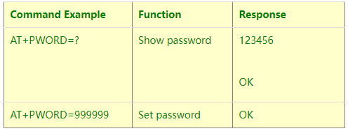
Downlink Command:
No downlink command for this feature.
4. Battery & How to replace
4.1 Battery Type and replace
LHT52 uses 2 x AAA LR03(1.5v) batteries. If the batteries running low (shows 2.1v in the platform). User can buy generic AAA battery and replace it.
Note:
- The LHT52 doesn’t have any screw, use can use nail to open it by the middle.
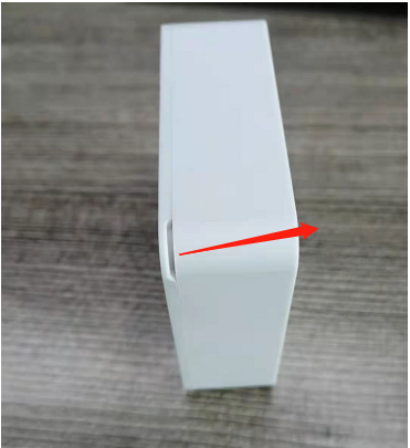
- Make sure the direction is correct when install the AAA batteries.

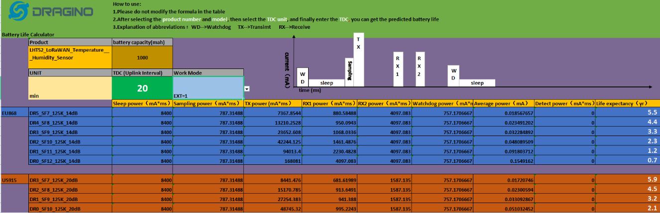
4.2 Power Consumption Analyze
Dragino battery powered product are all runs in Low Power mode. We have an update battery calculator which base on the measurement of the real device. User can use this calculator to check the battery life and calculate the battery life if want to use different transmit interval.
Instruction to use as below:
Step 1: Downlink the up-to-date DRAGINO_Battery_Life_Prediction_Table.xlsx from:
https://www.dragino.com/downloads/index.php?dir=LoRa_End_Node/Battery_Analyze/
Step 2: Open it and choose
- Product Model
- Uplink Interval
- Working Mode
And the Life expectation in difference case will be shown on the right.
5. Sensors and Accessories
5.1 Temperature Probe (AS-01)
External Temperature Probe base on DS18B20. (note: Default Package doesn’t include AS-01)
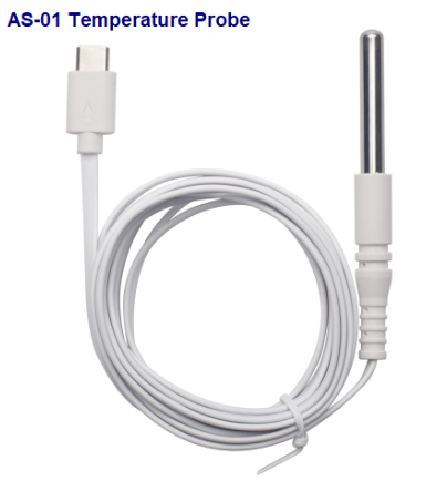
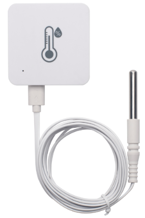
External Temperature Probe (AS-01):
- Resolution: 0.0625 °C
- ±0.5°C accuracy from -10°C to +85°C
- ±2°C accuracy from -55°C to +125°C
- Operating Range: -55 °C ~ 125 °C
- Cable Length: 2 meters
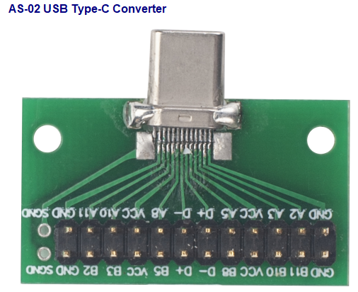
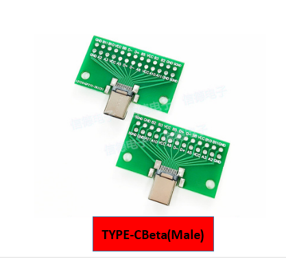
5.2 Program Converter (AS-02)
AS-02 is an optional accessory, it is USB Type-C converter. AS-02 provide below feature:
- Access AT console of LHT52 when used with USB-TTL adapter. See this link.
- Update firmware to LHT52 when used with DAP-Link adapter. See this link.
6. FAQ
6.1 How to use AT Command?
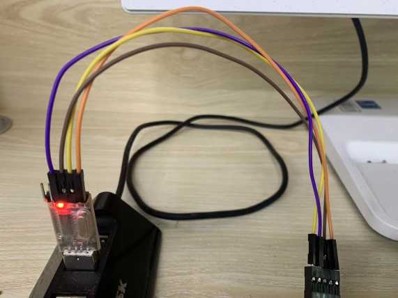
LHT65N supports AT Command set.User can use a USB to TTL adapter plus the Program Cable to connect to LHT65 for using AT command, as below.
Connection:
✓ USB to TTL GND <-->GND
✓ USB to TTL RXD <--> D+
✓ USB to TTL TXD <--> A11
✓ USB to TTL 3.3V <--> D-
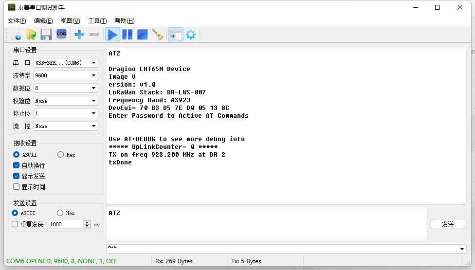
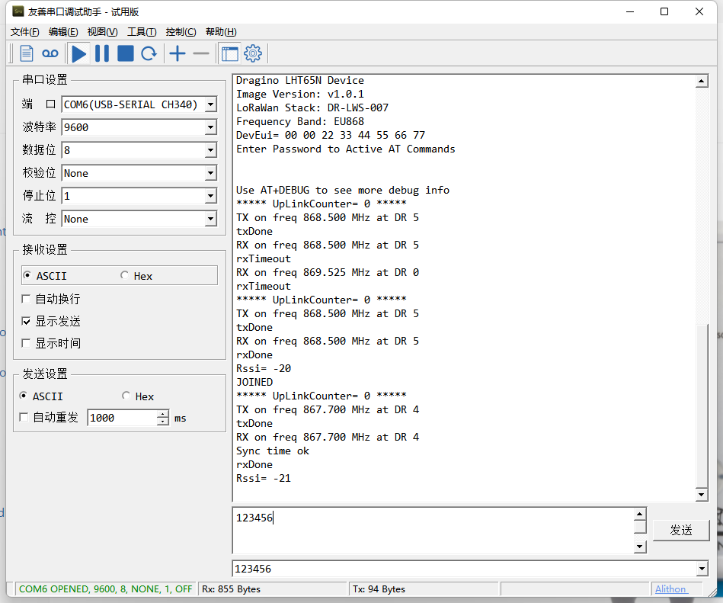
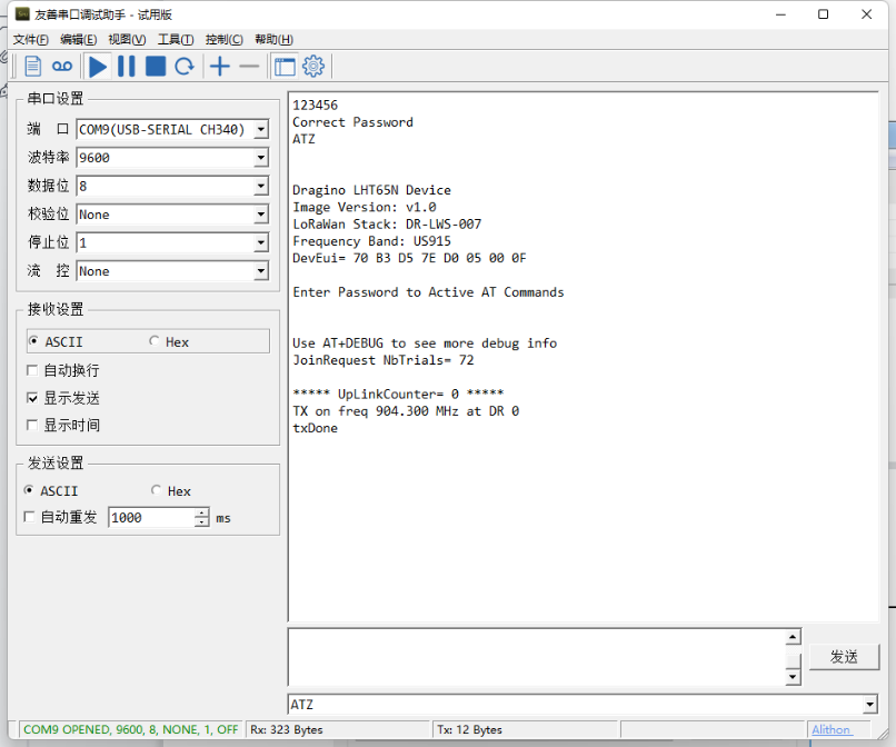
In PC, User needs to set serial tool(such as putty, SecureCRT) baud rate to 9600 to access to access serial console for LHT65N. The AT commands are disable by default and need to enter password (default:123456) to active it. Timeout to input AT Command is 5 min, after 5-minute, user need to input password again. User can use AT+DISAT command to disable AT command before timeout.
Input password and ATZ to activate LHT65N,As shown below:
AT Command List is as below:
AT+<CMD>? : Help on <CMD>
AT+<CMD> : Run <CMD>
AT+<CMD>=<value> : Set the value
AT+<CMD>=? : Get the value
AT+DEBUG: Set more info output
ATZ: Trig a reset of the MCU
AT+FDR: Reset Parameters to Factory Default, Keys Reserve
AT+DEUI: Get or Set the Device EUI
AT+DADDR: Get or Set the Device Address
AT+APPKEY: Get or Set the Application Key
AT+NWKSKEY: Get or Set the Network Session Key
AT+APPSKEY: Get or Set the Application Session Key
AT+APPEUI: Get or Set the Application EUI
AT+ADR: Get or Set the Adaptive Data Rate setting. (0: off, 1: on)
AT+TXP: Get or Set the Transmit Power (0-5, MAX:0, MIN:5, according to LoRaWAN Spec)
AT+DR: Get or Set the Data Rate. (0-7 corresponding to DR_X)
AT+DCS: Get or Set the ETSI Duty Cycle setting - 0=disable, 1=enable - Only for testing
AT+PNM: Get or Set the public network mode. (0: off, 1: on)
AT+RX2FQ: Get or Set the Rx2 window frequency
AT+RX2DR: Get or Set the Rx2 window data rate (0-7 corresponding to DR_X)
AT+RX1DL: Get or Set the delay between the end of the Tx and the Rx Window 1 in ms
AT+RX2DL: Get or Set the delay between the end of the Tx and the Rx Window 2 in ms
AT+JN1DL: Get or Set the Join Accept Delay between the end of the Tx and the Join Rx Window 1 in ms
AT+JN2DL: Get or Set the Join Accept Delay between the end of the Tx and the Join Rx Window 2 in ms
AT+NJM: Get or Set the Network Join Mode. (0: ABP, 1: OTAA)
AT+NWKID: Get or Set the Network ID
AT+FCU: Get or Set the Frame Counter Uplink
AT+FCD: Get or Set the Frame Counter Downlink
AT+CLASS: Get or Set the Device Class
AT+JOIN: Join network
AT+NJS: Get the join status
AT+SENDB: Send hexadecimal data along with the application port
AT+SEND: Send text data along with the application port
AT+RECVB: Print last received data in binary format (with hexadecimal values)
AT+RECV: Print last received data in raw format
AT+VER: Get current image version and Frequency Band
AT+CFM: Get or Set the confirmation mode (0-1)
AT+CFS: Get confirmation status of the last AT+SEND (0-1)
AT+SNR: Get the SNR of the last received packet
AT+RSSI: Get the RSSI of the last received packet
AT+TDC: Get or set the application data transmission interval in ms
AT+PORT: Get or set the application port
AT+DISAT: Disable AT commands
AT+PWORD: Set password, max 9 digits
AT+CHS: Get or Set Frequency (Unit: Hz) for Single Channel Mode
AT+CHE: Get or Set eight channels mode,Only for US915,AU915,CN470
AT+PDTA: Print the sector data from start page to stop page
AT+PLDTA: Print the last few sets of data
AT+CLRDTA: Clear the storage, record position back to 1st
AT+SLEEP: Set sleep mode
AT+EXT: Get or Set external sensor model
AT+BAT: Get the current battery voltage in mV
AT+CFG: Print all configurations
AT+WMOD: Get or Set Work Mode
AT+ARTEMP: Get or set the internal Temperature sensor alarm range
AT+CITEMP: Get or set the internal Temperature sensor collection interval in min
AT+SETCNT: Set the count at present
AT+RJTDC: Get or set the ReJoin data transmission interval in min
AT+RPL: Get or set response level
AT+TIMESTAMP: Get or Set UNIX timestamp in second
AT+LEAPSEC: Get or Set Leap Second
AT+SYNCMOD: Get or Set time synchronization method
AT+SYNCTDC: Get or set time synchronization interval in day
AT+PID: Get or set the PID
6.2 Where to use AT commands and Downlink commands
AT commands:
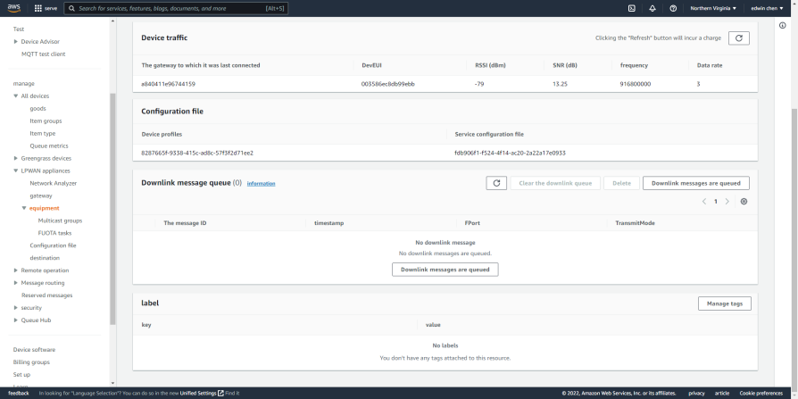
Downlink commands:
TTN:
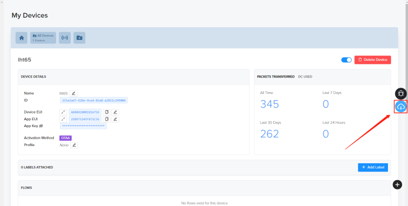
Helium:
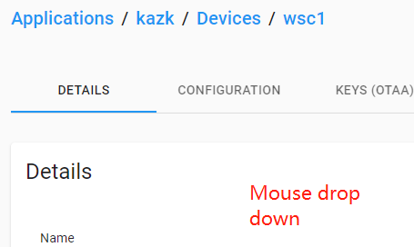
Chirpstack:The downlink window will not be displayed until the network is accessed
Aws:
6.3 How to change the uplink interval?
http://wiki.dragino.com/xwiki/bin/view/Main/How%20to%20set%20the%20transmit%20time%20interval/
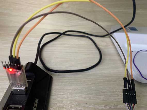
6.4 How to use TTL-USB to connect a PC to input AT commands?
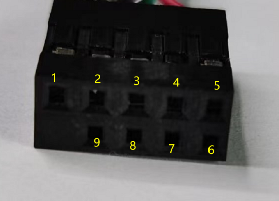
1 < - -> GND < - -> Black
5 < - -> RXD < - -> White
9 < - -> TXD < - -> Green
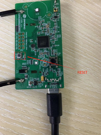
To switch from download mode to command mode, press reset key
In PC, User needs to set serial tool(such as putty, SecureCRT) baud rate to 9600 to access to access serial console for LHT65N. The AT commands are disable by default and need to enter password (default:123456) to active it. Timeout to input AT Command is 5 min, after 5-minute, user need to input password again. User can use AT+DISAT command to disable AT command before timeout.
Input password and ATZ to activate LHT65N,As shown below:
6.5 How to use TTL-USB to connect PC to upgrade firmware?
1 < - -> GND < - -> Black
4 < - -> 3.3V < - -> Blue
5 < - -> RXD < - -> White
9 < - -> TXD < - -> Green
Press reset after connecting the 4boot cable to enter the download mode.
Step1: Install TremoProgrammer first.
Step2:Download the LHT65N image files.
Step3:Select the serial port and baud rate of the device and the firmware to be upgraded.
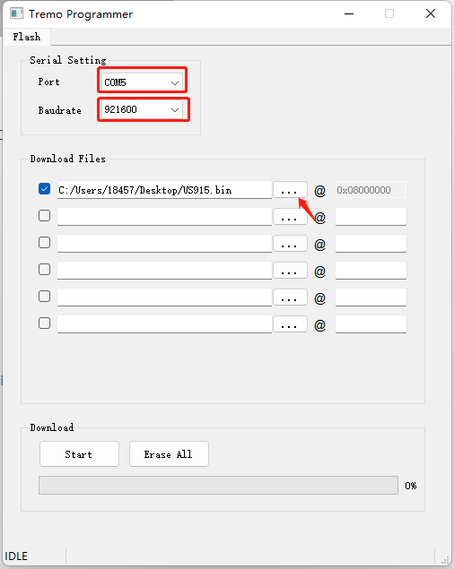
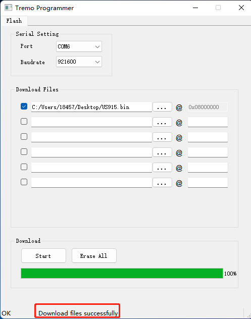
Step4:Click Start
7. Order Info
Part Number: LHT65N-XX-YY
XX : The default frequency band
AS923: LoRaWAN AS923 band
AU915: LoRaWAN AU915 band
EU433: LoRaWAN EU433 band
EU868: LoRaWAN EU868 band
KR920: LoRaWAN KR920 band
US915: LoRaWAN US915 band
IN865: LoRaWAN IN865 band
CN470: LoRaWAN CN470 band
YY: Sensor Accessories
E3: External Temperature Probe
8. Packing Info
Package Includes:
LHT65N Temperature & Humidity Sensor x 1
Optional external sensor
Dimension and weight:
Device Size: 10 x 10 x 3.5 cm
Device Weight: 120.5g
9. Reference material
10. FCC Warning
This device complies with part 15 of the FCC Rules.Operation is subject to the following two conditions:
(1) This device may not cause harmful interference;
(2) this device must accept any interference received, including interference that may cause undesired operation.