Contents:
1. Introduction
1.1 What is LoRaWAN Distance Detection Sensor
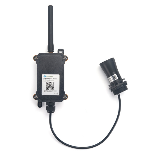
The Dragino LDDS75 is a LoRaWAN Distance Detection Sensor for Internet of Things solution. It is used to measure the distance between the sensor and a flat object. The distance detection sensor is a module that uses ultrasonic sensing technology for distance measurement, and temperature compensation is performed internally to improve the reliability of data. The LDDS75 can be applied to scenarios such as horizontal distance measurement, liquid level measurement, parking management system, object proximity and presence detection, intelligent trash can management system, robot obstacle avoidance, automatic control, sewer, bottom water level monitoring, etc.
It detects the distance between the measured object and the sensor, and uploads the value via wireless to LoRaWAN IoT Server.
The LoRa wireless technology used in LDDS75 allows device to send data and reach extremely long ranges at low data-rates. It provides ultra-long range spread spectrum communication and high interference immunity whilst minimizing current consumption.
LDDS75 is powered by 4000mA or 8500mAh Li-SOCI2 battery; It is designed for long term use up to 10 years*.
Each LDDS75 pre-loads with a set of unique keys for LoRaWAN registrations, register these keys to local LoRaWAN server and it will auto connect if there is network coverage, after power on.
* Actually lifetime depends on network coverage and uplink interval and other factors

1.2 Features
- LoRaWAN 1.0.3 Class A
- Ultra low power consumption
- Distance Detection by Ultrasonic technology
- Flat object range 280mm - 7500mm
- Accuracy: ±(1cm+S*0.3%) (S: Distance)
- Cable Length : 25cm
- Bands: CN470/EU433/KR920/US915/EU868/AS923/AU915/IN865
- AT Commands to change parameters
- Uplink on periodically
- Downlink to change configure
- IP66 Waterproof Enclosure
- 4000mAh or 8500mAh Battery for long term use
1.3 Specification
1.3.1 Rated environmental conditions
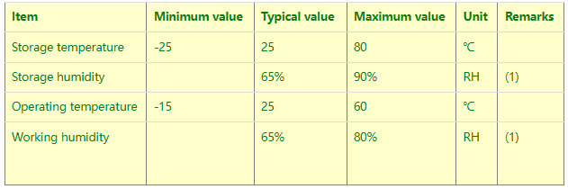
Remarks: (1) a. When the ambient temperature is 0-39 ℃, the maximum humidity is 90% (non-condensing);
b. When the ambient temperature is 40-50 ℃, the highest humidity is the highest humidity in the natural world at the current temperature (no condensation)
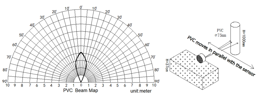
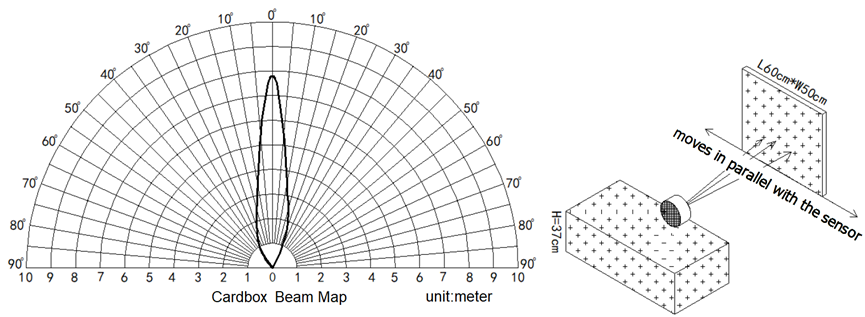
1.3.2 Effective measurement range Reference beam pattern
(1) The tested object is a white cylindrical tube made of PVC, with a height of 100cm and a diameter of 7.5cm.
(2) The object to be tested is a "corrugated cardboard box" perpendicular to the central axis of 0 °, and the length * width is 60cm * 50cm.
1.5 Applications
- Horizontal distance measurement
- Liquid level measurement
- Parking management system
- Object proximity and presence detection
- Intelligent trash can management system
- Robot obstacle avoidance
- Automatic control
- Sewer
- Bottom water level monitoring
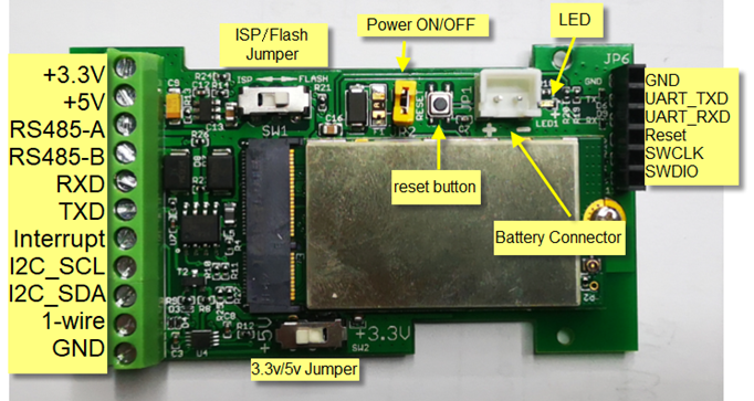
1.6 Pin mapping and power on
2. Configure LDDS75 to connect to LoRaWAN network
2.1 How it works
The LDDS75 is configured as LoRaWAN OTAA Class A mode by default. It has OTAA keys to join LoRaWAN network. To connect a LoRaWAN network, you need to input the OTAA keys in the LoRaWAN IoT server and power on the LDDS75. If there is coverage of the LoRaWAN network, it will automatically join the network via OTAA and start to send the sensor value
In case you can't set the OTAA keys in the LoRaWAN OTAA server, and you have to use the keys from the server, you can use AT Commands to set the keys in the LDDS75.
2.2 Quick guide to connect to LoRaWAN server (OTAA)
Following is an example for how to join the TTN v3 LoRaWAN Network. Below is the network structure; we use the LG308 as a LoRaWAN gateway in this example.
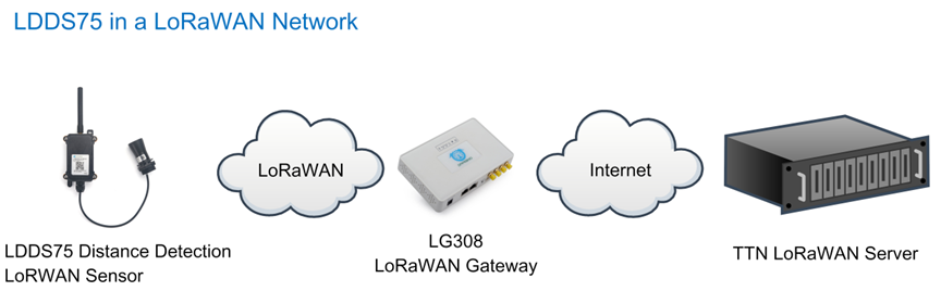
The LG308 is already set to connected to TTN network , so what we need to now is configure the TTN server.
Step 1: Create a device in TTN with the OTAA keys from LDDS75.
Each LDDS75 is shipped with a sticker with the default device keys, user can find this sticker in the box. it looks like below.
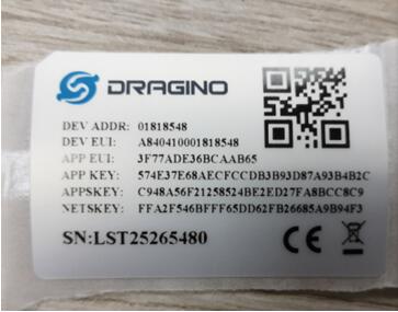
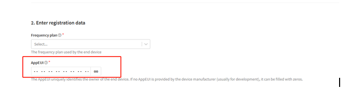
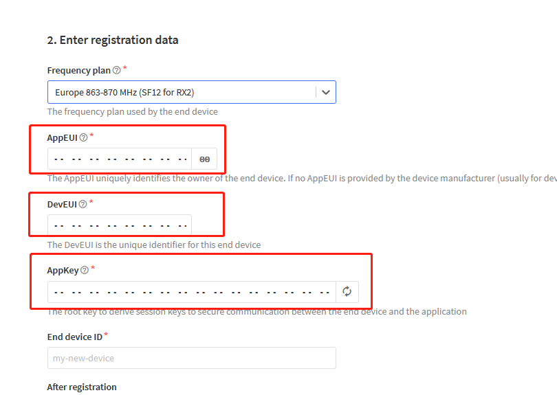
For OTAA registration, we need to set APP EUI/ APP KEY/ DEV EUI. Some server might no need to set APP EUI.
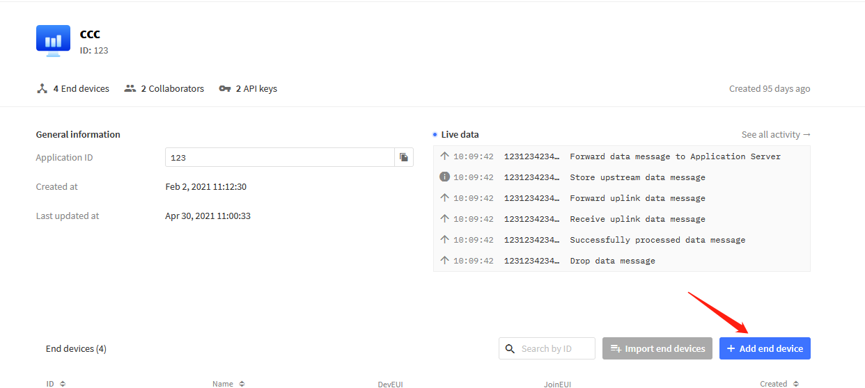
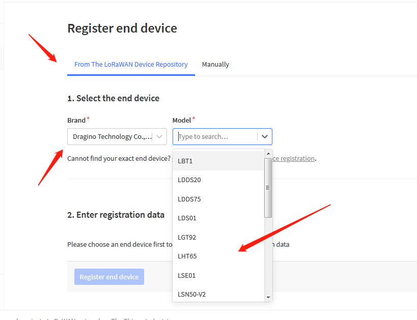
Enter these keys in the LoRaWAN Server portal. Below is TTN V3 screen shot:
Add APP EUI in the application
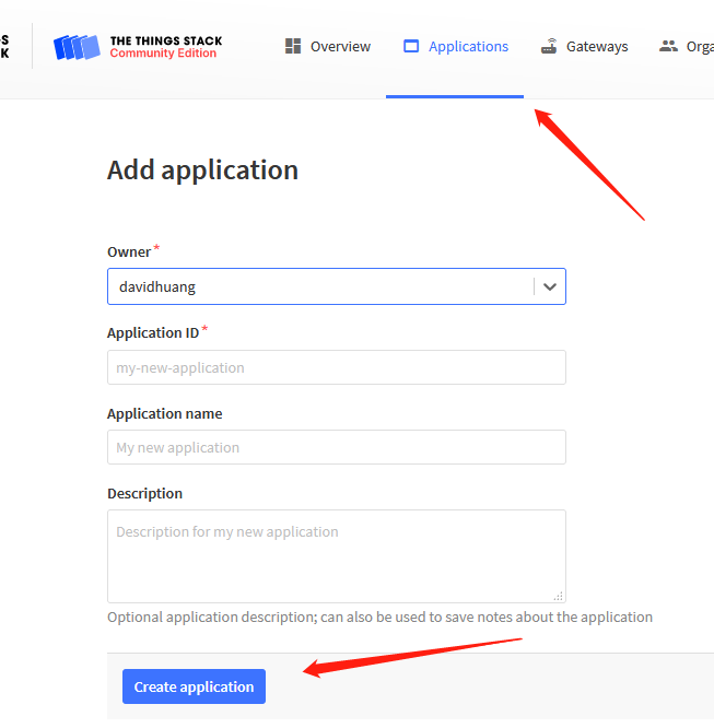
You can also choose to create the device manually.
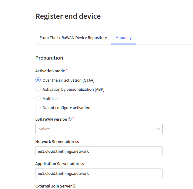
Add APP KEY and DEV EUI
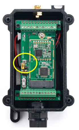
Step 2: Power on LDDS75
Put a Jumper on JP2 to power on the device. ( The Switch must be in FLASH position).
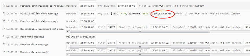
Step 3: The LDDS75 will auto join to the TTN network. After join success, it will start to upload messages to TTN and you can see the messages in the panel.
2.3 Uplink Payload
LDDS75 will uplink payload via LoRaWAN with below payload format:
Uplink payload includes in total 4 bytes.
Payload for firmware version v1.1.4. . Before v1.1.3, there is on two fields: BAT and Distance
Size (bytes) | 2 | 2 | 1 | 2 | 1 |
|---|---|---|---|---|---|
| Value | BAT | (unit: mm) | Digital Interrupt (Optional) | Sensor Flag |

2.3.1 Battery Info
Check the battery voltage for LDDS75.
Ex1: 0x0B45 = 2885mV
Ex2: 0x0B49 = 2889mV
2.3.2 Distance
Get the distance. Flat object range 280mm - 7500mm.
For example, if the data you get from the register is 0x0B 0x05, the distance between the sensor and the measured object is 0B05(H) = 2821 (D) = 2821 mm.
- If the sensor value is 0x0000, it means system doesn’t detect ultrasonic sensor.
- If the sensor value lower than 0x0118 (280mm), the sensor value will be invalid. Since v1.1.4, all value lower than 280mm will be set to 0x0014(20mm) which means the value is invalid.
2.3.3 Interrupt Pin
This data field shows if this packet is generated by interrupt or not. Click here for the hardware and software set up.
Example:
0x00: Normal uplink packet.
0x01: Interrupt Uplink Packet.
2.3.4 DS18B20 Temperature sensor
This is optional, user can connect external DS18B20 sensor to the +3.3v, 1-wire and GND pin . and this field will report temperature.
Example:
If payload is: 0105H: (0105 & FC00 == 0), temp = 0105H /10 = 26.1 degree
If payload is: FF3FH : (FF3F & FC00 == 1) , temp = (FF3FH - 65536)/10 = -19.3 degrees.
Note: DS18B20 feature is supported in the hardware version > v1.3 which made since early of 2021.
2.3.5 Sensor Flag
0x01: Detect Ultrasonic Sensor
0x00: No Ultrasonic Sensor
2.3.6 Decode payload in The Things Network
While using TTN network, you can add the payload format to decode the payload.
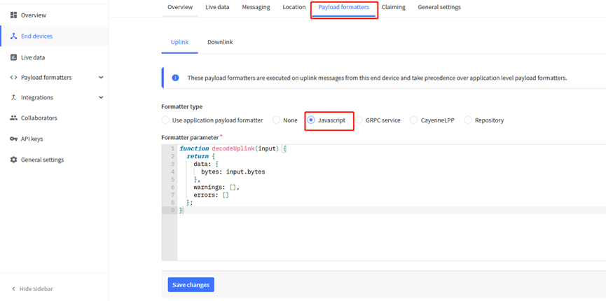
The payload decoder function for TTN V3 is here:
LDDS75 TTN V3 Payload Decoder: http://www.dragino.com/downloads/index.php?dir=LoRa_End_Node/LDDS75/Payload_Decoder/
2.4 Uplink Interval
The LDDS75 by default uplink the sensor data every 20 minutes. User can change this interval by AT Command or LoRaWAN Downlink Command. See this link: Change Uplink Interval
2.5 Show Data in DataCake IoT Server
DATACAKE provides a human friendly interface to show the sensor data, once we have data in TTN, we can use DATACAKE to connect to TTN and see the data in DATACAKE. Below are the steps:
Step 1: Be sure that your device is programmed and properly connected to the network at this time.
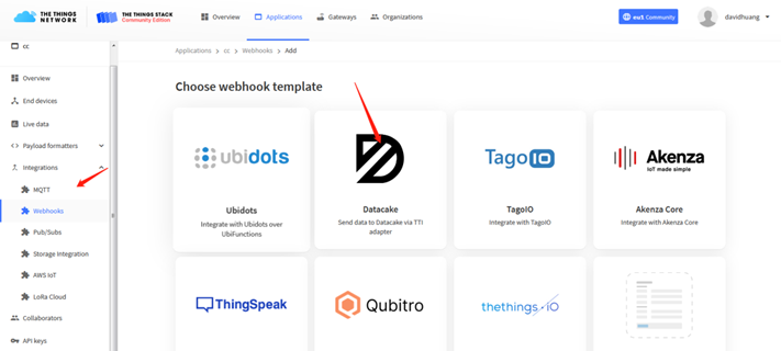
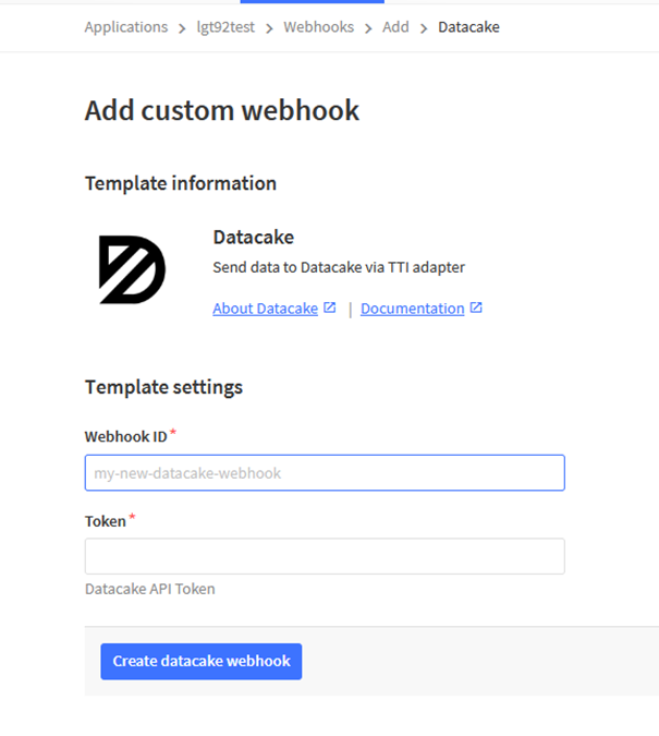
Step 2: To configure the Application to forward data to DATACAKE you will need to add integration. To add the DATACAKE integration, perform the following steps:
Step 3: Create an account or log in Datacake.
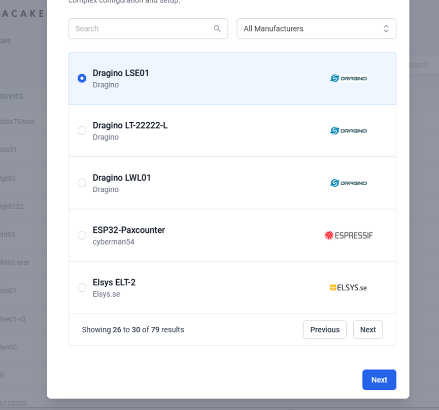
Step 4: Search the LDDS75 and add DevEUI.
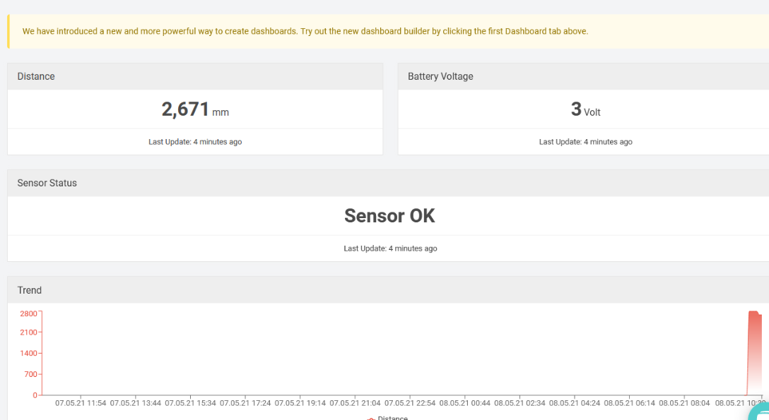
After added, the sensor data arrive TTN V3, it will also arrive and show in Datacake.
2.6 Frequency Plans
The LDDS75 uses OTAA mode and below frequency plans by default. If user want to use it with different frequency plan, please refer the AT command sets.
2.6.1 EU863-870 (EU868)
Uplink:
868.1 - SF7BW125 to SF12BW125
868.3 - SF7BW125 to SF12BW125 and SF7BW250
868.5 - SF7BW125 to SF12BW125
867.1 - SF7BW125 to SF12BW125
867.3 - SF7BW125 to SF12BW125
867.5 - SF7BW125 to SF12BW125
867.7 - SF7BW125 to SF12BW125
867.9 - SF7BW125 to SF12BW125
868.8 - FSK
Downlink:
Uplink channels 1-9 (RX1)
869.525 - SF9BW125 (RX2 downlink only)
2.6.2 US902-928(US915)
Used in USA, Canada and South America. Default use CHE=2
Uplink:
903.9 - SF7BW125 to SF10BW125
904.1 - SF7BW125 to SF10BW125
904.3 - SF7BW125 to SF10BW125
904.5 - SF7BW125 to SF10BW125
904.7 - SF7BW125 to SF10BW125
904.9 - SF7BW125 to SF10BW125
905.1 - SF7BW125 to SF10BW125
905.3 - SF7BW125 to SF10BW125
Downlink:
923.3 - SF7BW500 to SF12BW500
923.9 - SF7BW500 to SF12BW500
924.5 - SF7BW500 to SF12BW500
925.1 - SF7BW500 to SF12BW500
925.7 - SF7BW500 to SF12BW500
926.3 - SF7BW500 to SF12BW500
926.9 - SF7BW500 to SF12BW500
927.5 - SF7BW500 to SF12BW500
923.3 - SF12BW500(RX2 downlink only)
2.6.3 CN470-510 (CN470)
Used in China, Default use CHE=1
Uplink:
486.3 - SF7BW125 to SF12BW125
486.5 - SF7BW125 to SF12BW125
486.7 - SF7BW125 to SF12BW125
486.9 - SF7BW125 to SF12BW125
487.1 - SF7BW125 to SF12BW125
487.3 - SF7BW125 to SF12BW125
487.5 - SF7BW125 to SF12BW125
487.7 - SF7BW125 to SF12BW125
Downlink:
506.7 - SF7BW125 to SF12BW125
506.9 - SF7BW125 to SF12BW125
507.1 - SF7BW125 to SF12BW125
507.3 - SF7BW125 to SF12BW125
507.5 - SF7BW125 to SF12BW125
507.7 - SF7BW125 to SF12BW125
507.9 - SF7BW125 to SF12BW125
508.1 - SF7BW125 to SF12BW125
505.3 - SF12BW125 (RX2 downlink only)
2.6.4 AU915-928(AU915)
Default use CHE=2
Uplink:
916.8 - SF7BW125 to SF12BW125
917.0 - SF7BW125 to SF12BW125
917.2 - SF7BW125 to SF12BW125
917.4 - SF7BW125 to SF12BW125
917.6 - SF7BW125 to SF12BW125
917.8 - SF7BW125 to SF12BW125
918.0 - SF7BW125 to SF12BW125
918.2 - SF7BW125 to SF12BW125
Downlink:
923.3 - SF7BW500 to SF12BW500
923.9 - SF7BW500 to SF12BW500
924.5 - SF7BW500 to SF12BW500
925.1 - SF7BW500 to SF12BW500
925.7 - SF7BW500 to SF12BW500
926.3 - SF7BW500 to SF12BW500
926.9 - SF7BW500 to SF12BW500
927.5 - SF7BW500 to SF12BW500
923.3 - SF12BW500(RX2 downlink only)
2.6.5 AS920-923 & AS923-925 (AS923)
Default Uplink channel:
923.2 - SF7BW125 to SF10BW125
923.4 - SF7BW125 to SF10BW125
Additional Uplink Channel:
(OTAA mode, channel added by JoinAccept message)
AS920~AS923 for Japan, Malaysia, Singapore:
922.2 - SF7BW125 to SF10BW125
922.4 - SF7BW125 to SF10BW125
922.6 - SF7BW125 to SF10BW125
922.8 - SF7BW125 to SF10BW125
923.0 - SF7BW125 to SF10BW125
922.0 - SF7BW125 to SF10BW125
AS923 ~ AS925 for Brunei, Cambodia, Hong Kong, Indonesia, Laos, Taiwan, Thailand, Vietnam:
923.6 - SF7BW125 to SF10BW125
923.8 - SF7BW125 to SF10BW125
924.0 - SF7BW125 to SF10BW125
924.2 - SF7BW125 to SF10BW125
924.4 - SF7BW125 to SF10BW125
924.6 - SF7BW125 to SF10BW125
Downlink:
Uplink channels 1-8 (RX1)
923.2 - SF10BW125 (RX2)
2.6.6 KR920-923 (KR920)
Default channel:
922.1 - SF7BW125 to SF12BW125
922.3 - SF7BW125 to SF12BW125
922.5 - SF7BW125 to SF12BW125
Uplink: (OTAA mode, channel added by JoinAccept message)
922.1 - SF7BW125 to SF12BW125
922.3 - SF7BW125 to SF12BW125
922.5 - SF7BW125 to SF12BW125
922.7 - SF7BW125 to SF12BW125
922.9 - SF7BW125 to SF12BW125
923.1 - SF7BW125 to SF12BW125
923.3 - SF7BW125 to SF12BW125
Downlink:
Uplink channels 1-7(RX1)
921.9 - SF12BW125 (RX2 downlink only; SF12BW125 might be changed to SF9BW125)
2.6.7 IN865-867 (IN865)
Uplink:
865.0625 - SF7BW125 to SF12BW125
865.4025 - SF7BW125 to SF12BW125
865.9850 - SF7BW125 to SF12BW125
Downlink:
Uplink channels 1-3 (RX1)
866.550 - SF10BW125 (RX2)
2.7 LED Indicator
The LLDS12 has an internal LED which is to show the status of different state.
- The sensor is detected when the device is turned on, and it will flash 4 times quickly when it is detected.
- Blink once when device transmit a packet.
2.8 Firmware Change Log
Firmware download link: http://www.dragino.com/downloads/index.php?dir=LoRa_End_Node/LLDS12/Firmware/
Firmware Upgrade Method: Firmware Upgrade Instruction
3. LiDAR ToF Measurement
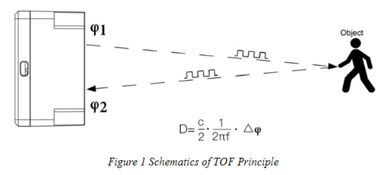
3.1 Principle of Distance Measurement
The LiDAR probe is based on TOF, namely, Time of Flight principle. To be specific, the product emits modulation wave of near infrared ray on a periodic basis, which will be reflected after contacting object. The product obtains the time of flight by measuring round-trip phase difference and then calculates relative range between the product and the detection object, as shown below.
3.2 Distance Measurement Characteristics
With optimization of light path and algorithm, The LiDAR probe has minimized influence from external environment on distance measurement performance. Despite that, the range of distance measurement may still be affected by the environment illumination intensity and the reflectivity of detection object. As shown in below:
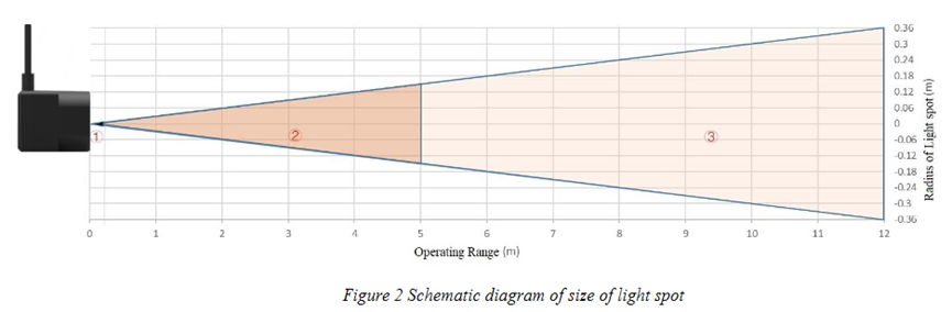
① Represents the detection blind zone of The LiDAR probe, 0-10cm, within which the output data is unreliable.
② Represents the operating range of The LiDAR probe detecting black target with 10% reflectivity, 0.1-5m.
③ Represents the operating range of The LiDAR probe detecting white target with 90% reflectivity, 0.1-12m.
Vertical Coordinates: Represents the radius of light spot for The LiDAR probe at the different distances. The diameter of light spot depends on the FOV of The LiDAR probe (the term of FOV generally refers to the smaller value between the receiving angle and the transmitting angle), which is calculated as follows:
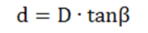
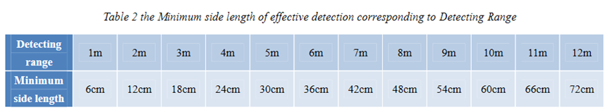
In the formula above, d is the diameter of light spot; D is detecting range; β is the value of the receiving angle of The LiDAR probe, 3.6°. Correspondence between the diameter of light spot and detecting range is given in Table below.
If the light spot reaches two objects with different distances, as shown in Figure 3, the output distance value will be a value between the actual distance values of the two objects. For a high accuracy requirement in practice, the above situation should be noticed to avoid the measurement error.
3.3 Notice of usage:
Possible invalid /wrong reading for LiDAR ToF tech:
- Measure high reflectivity object such as: Mirror, Smooth ceramic tile, static milk surface, will have possible wrong readings.
- While there is transparent object such as glass, water drop between the measured object and the LiDAR sensor, the reading might wrong.
- The LiDAR probe is cover by dirty things; the reading might be wrong. In this case, need to clean the probe.
- The sensor window is made by Acrylic. Don’t touch it with alcohol material. This will destroy the sensor window.
4. Configure LLDS12 via AT Command or LoRaWAN Downlink
Use can configure LLDS12 via AT Command or LoRaWAN Downlink.
AT Command Connection: See FAQ.
LoRaWAN Downlink instruction for different platforms: IoT LoRaWAN Server
There are two kinds of commands to configure LLDS12, they are:
General Commands.
These commands are to configure:
General system settings like: uplink interval.
LoRaWAN protocol & radio related command.
They are same for all Dragino Device which support DLWS-005 LoRaWAN Stack. These commands can be found on the wiki: End Device AT Commands and Downlink Command
Commands special design for LLDS12
These commands only valid for LLDS12, as below:
4.1 Set Transmit Interval Time
Feature: Change LoRaWAN End Node Transmit Interval.
AT Command: AT+TDC
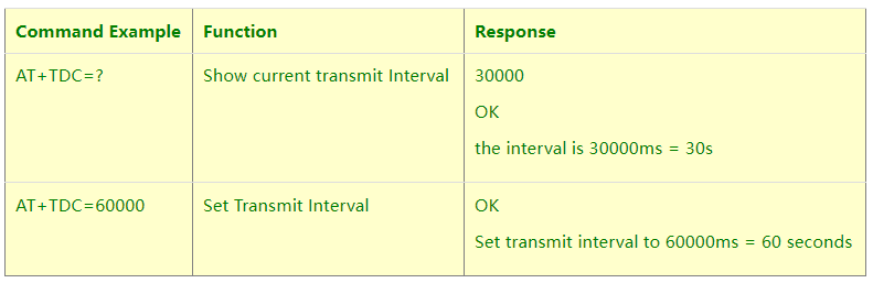
Downlink Command: 0x01
Format: Command Code (0x01) followed by 3 bytes time value.
If the downlink payload=0100003C, it means set the END Node’s Transmit Interval to 0x00003C=60(S), while type code is 01.
Example 1: Downlink Payload: 0100001E // Set Transmit Interval (TDC) = 30 seconds
Example 2: Downlink Payload: 0100003C // Set Transmit Interval (TDC) = 60 seconds
4.2 Set Interrupt Mode
Feature, Set Interrupt mode for GPIO_EXIT.
AT Command: AT+INTMOD
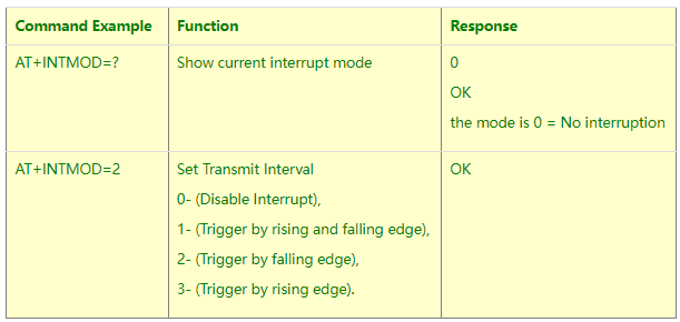
Downlink Command: 0x06
Format: Command Code (0x06) followed by 3 bytes.
This means that the interrupt mode of the end node is set to 0x000003=3 (rising edge trigger), and the type code is 06.
Example 1: Downlink Payload: 06000000 // Turn off interrupt mode
Example 2: Downlink Payload: 06000003 // Set the interrupt mode to rising edge trigger
4.3 Get Firmware Version Info
Feature: use downlink to get firmware version.
Downlink Command: 0x26
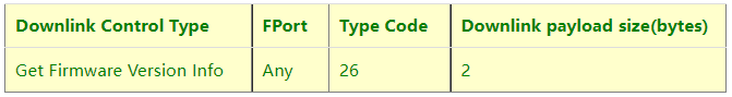
- Reply to the confirmation package: 26 01
- Reply to non-confirmed packet: 26 00
Device will send an uplink after got this downlink command. With below payload:
Configures info payload:
Size(bytes) | 1 | 1 | 1 | 1 | 1 | 5 | 1 |
|---|---|---|---|---|---|---|---|
| Value | Software Type | Frequency Band | Sub-band | Firmware Version | Sensor Type | Reserve | Message Type |
Software Type: Always 0x03 for LLDS12
Frequency Band:
*0x01: EU868
*0x02: US915
*0x03: IN865
*0x04: AU915
*0x05: KZ865
*0x06: RU864
*0x07: AS923
*0x08: AS923-1
*0x09: AS923-2
*0xa0: AS923-3
Sub-Band: value 0x00 ~ 0x08
Firmware Version: 0x0100, Means: v1.0.0 version
Sensor Type:
0x01: LSE01
0x02: LDDS75
0x03: LDDS20
0x04: LLMS01
0x05: LSPH01
0x06: LSNPK01
0x07: LLDS12
5. Battery & How to replace
5.1 Battery Type
LLDS12 is equipped with a 8500mAH ER26500 Li-SOCI2 battery. The battery is un-rechargeable battery with low discharge rate targeting for 8~10 years use. This type of battery is commonly used in IoT target for long-term running, such as water meter.
The discharge curve is not linear so can’t simply use percentage to show the battery level. Below is the battery performance.
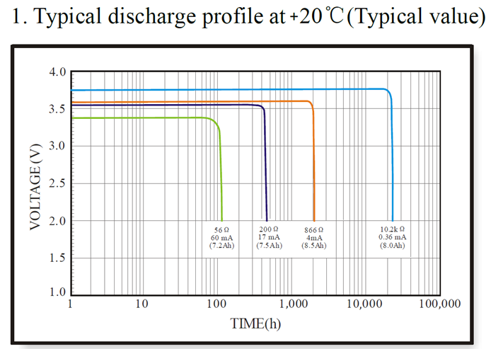
Minimum Working Voltage for the LLDS12:
LLDS12: 2.45v ~ 3.6v
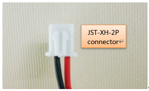
5.2 Replace Battery
Any battery with range 2.45 ~ 3.6v can be a replacement. We recommend to use Li-SOCl2 Battery.
And make sure the positive and negative pins match.
5.3 Power Consumption Analyze
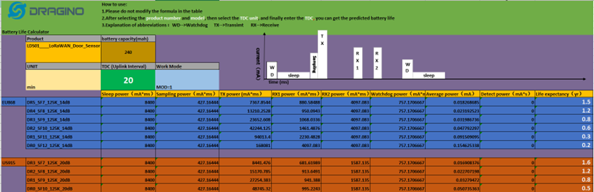
Dragino Battery powered product are all runs in Low Power mode. We have an update battery calculator which base on the measurement of the real device. User can use this calculator to check the battery life and calculate the battery life if want to use different transmit interval.
Instruction to use as below:
Step 1: Downlink the up-to-date DRAGINO_Battery_Life_Prediction_Table.xlsx from:
https://www.dragino.com/downloads/index.pHp?dir=LoRa_End_Node/Battery_Analyze/
Step 2: Open it and choose
- Product Model
- Uplink Interval
- Working Mode
And the Life expectation in difference case will be shown on the right.
The battery related documents as below:
5.3.1 Battery Note
The Li-SICO battery is designed for small current / long period application. It is not good to use a high current, short period transmit method. The recommended minimum period for use of this battery is 5 minutes. If you use a shorter period time to transmit LoRa, then the battery life may be decreased.
5.3.2 Replace the battery
You can change the battery in the LLDS12.The type of battery is not limited as long as the output is between 3v to 3.6v. On the main board, there is a diode (D1) between the battery and the main circuit. If you need to use a battery with less than 3.3v, please remove the D1 and shortcut the two pads of it so there won’t be voltage drop between battery and main board.
The default battery pack of LLDS12 includes a ER26500 plus super capacitor. If user can’t find this pack locally, they can find ER26500 or equivalence, which will also work in most case. The SPC can enlarge the battery life for high frequency use (update period below 5 minutes)
6. Use AT Command
6.1 Access AT Commands
LLDS12 supports AT Command set in the stock firmware. You can use a USB to TTL adapter to connect to LLDS12 for using AT command, as below.
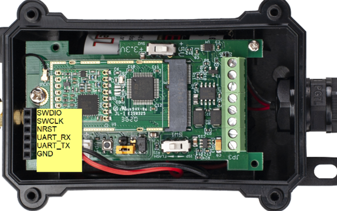
Connection:
USB TTL GND <----> GND
USB TTL TXD <----> UART_RXD
USB TTL RXD <----> UART_TXD
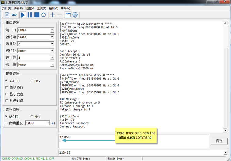
In the PC, you need to set the serial baud rate to 9600 to access the serial console for LLDS12.
LLDS12 will output system info once power on as below:
Valid AT Command please check Configure Device.
7. FAQ
7.1 How to change the LoRa Frequency Bands/Region
You can follow the instructions for how to upgrade image.
When downloading the images, choose the required image file for download.
8. Trouble Shooting
8.1 AT Commands input doesn’t work
In the case if user can see the console output but can’t type input to the device. Please check if you already include the ENTER while sending out the command. Some serial tool doesn’t send ENTER while press the send key, user need to add ENTER in their string.
8.2 Significant error between the output distant value of LiDAR and actual distance
Cause ①:Due to the physical principles of The LiDAR probe, the above phenomenon is likely to occur if the detection object is the material with high reflectivity (such as mirror, smooth floor tile, etc.) or transparent substance (such as glass and water, etc.)
Troubleshooting: Please avoid use of this product under such circumstance in practice.
Cause ②: The IR-pass filters are blocked.
Troubleshooting: please use dry dust-free cloth to gently remove the foreign matter.
9. Order Info
Part Number: LLDS12-XX
XX: The default frequency band
- AS923: LoRaWAN AS923 band
- AU915: LoRaWAN AU915 band
- EU433: LoRaWAN EU433 band
- EU868: LoRaWAN EU868 band
- KR920: LoRaWAN KR920 band
- US915: LoRaWAN US915 band
- IN865: LoRaWAN IN865 band
- CN470: LoRaWAN CN470 band
10. Packing Info
Package Includes:
- LLDS12 LoRaWAN LiDAR Distance Sensor x 1
Dimension and weight:
- Device Size: cm
- Device Weight: g
- Package Size / pcs : cm
- Weight / pcs : g
11. Support
- Support is provided Monday to Friday, from 09:00 to 18:00 GMT+8. Due to different timezones we cannot offer live support. However, your questions will be answered as soon as possible in the before-mentioned schedule.
- Provide as much information as possible regarding your enquiry (product models, accurately describe your problem and steps to replicate it etc) and send a mail to support@dragino.com.