DS20L -- LoRaWAN Smart Distance Detector User Manual 01
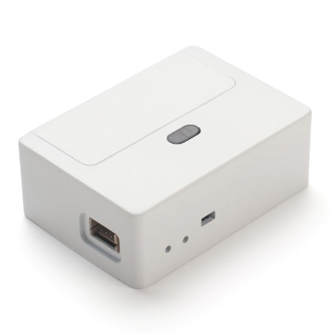
Table of Contents:
- 1. Introduction
- 2. Configure DS20L to connect to LoRaWAN network
- 3. Configure DS20L
- 4. Battery & Power Consumption
- 5. OTA Firmware update
- 6. FAQ
- 7. Trouble Shooting
- 8. Order Info
- 9. Packing Info
- 10. Support
1. Introduction
1.1 What is LoRaWAN Smart Distance Detector
The Dragino DS20L is a smart distance detector base on long-range wireless LoRaWAN technology. It uses LiDAR sensor to detect the distance between DS20L and object, then DS20L will send the distance data to the IoT Platform via LoRaWAN. DS20L can measure range between 3cm ~ 200cm.
DS20L allows users to send data and reach extremely long ranges via LoRaWAN. It provides ultra-long range spread spectrum communication and high interference immunity whilst minimizing current
consumption. It targets professional wireless sensor network applications such smart cities, building automation, and so on.
DS20L has a built-in 2400mAh non-chargeable battery for long-term use up to several years*. Users can also power DS20L with an external power source for continuous measuring and distance alarm / counting purposes.
DS20L is fully compatible with LoRaWAN v1.0.3 Class A protocol, it can work with a standard LoRaWAN gateway.
1.2 Features
- LoRaWAN Class A protocol
- LiDAR distance detector, range 3 ~ 200cm
- Periodically detect or continuously detect mode
- AT Commands to change parameters
- Remotely configure parameters via LoRaWAN Downlink
- Alarm & Counting mode
- Firmware upgradable via program port or LoRa protocol
- Built-in 2400mAh battery or power by external power source
1.3 Specification
LiDAR Sensor:
- Operation Temperature: -40 ~ 80 °C
- Operation Humidity: 0~99.9%RH (no Dew)
- Storage Temperature: -10 ~ 45°C
- Measure Range: 3cm~200cm @ 90% reflectivity
- Accuracy: ±2cm @ (3cm~100cm); ±5% @ (100~200cm)
- ToF FoV: ±9°, Total 18°
- Light source: VCSEL
1.4 Power Consumption
Battery Power Mode:
- Idle: 3uA @ 3.3v
- Max : 360 mA
Continuously mode:
- Idle: 21 mA @ 3.3v
- Max : 360 mA
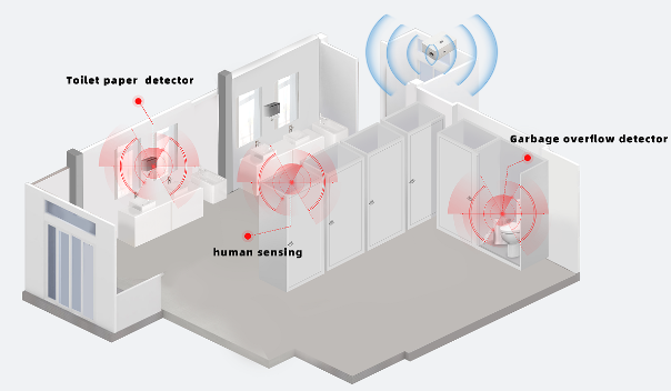
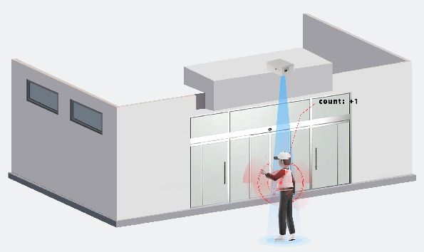
1.5 Use Case
Regular Distance Detect
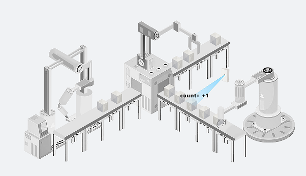
Counting / Alarm
2. Configure DS20L to connect to LoRaWAN network
2.1 How it works
The DS20L is configured as LoRaWAN OTAA Class A mode by default. It has OTAA keys to join LoRaWAN network. To connect a local LoRaWAN network, you need to input the OTAA keys in the LoRaWAN IoT server and press the button to activate the DS20L. It will automatically join the network via OTAA and start to send the sensor value. The default uplink interval is 20 minutes.
2.2 Quick guide to connect to LoRaWAN server (OTAA)
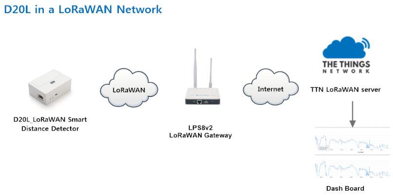
Following is an example for how to join the TTN v3 LoRaWAN Network. Below is the network structure; we use the LPS8v2 as a LoRaWAN gateway in this example.
The LPS8v2 is already set to connected to TTN network , so what we need to now is configure the TTN server.
Step 1: Create a device in TTN with the OTAA keys from DS20L.
Each DS20L is shipped with a sticker with the default device EUI as below:
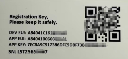
You can enter this key in the LoRaWAN Server portal. Below is TTN V3 screenshot:
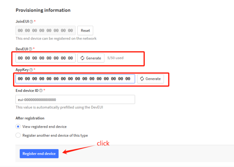
Register the device
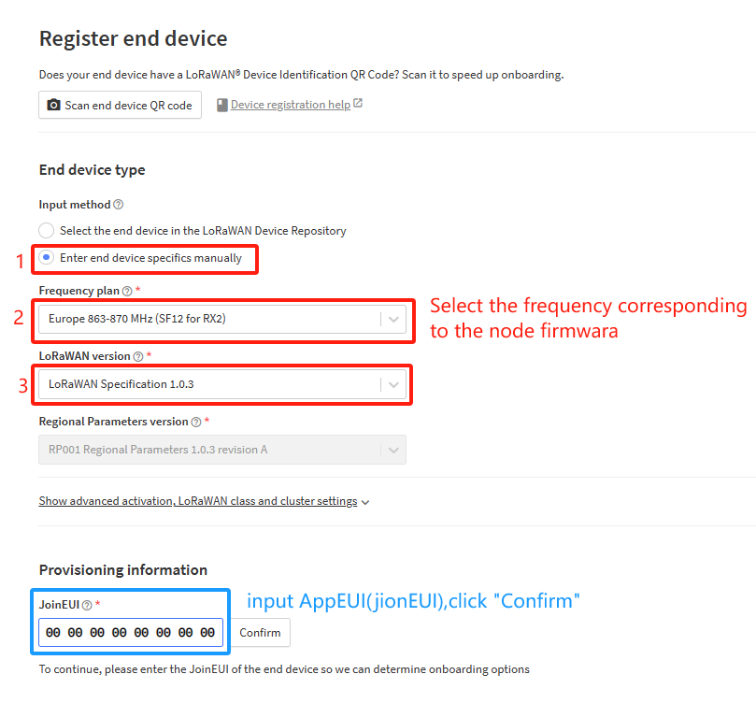
Add DevEUI and AppKey
Step 2: Activate DS20L
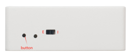
Press the button for 5 seconds to activate the DS20L.
The switch is switched to E and the external power supply is used.
The switch is switched to I and DS20L will be power by the built-in battery.
Green led will fast blink 5 times, device will enter OTA mode for 3 seconds. And then start to JOIN LoRaWAN network. Green led will solidly turn on for 5 seconds after joined in network.
After join success, it will start to upload messages to TTN and you can see the messages in the panel.
2.3 Uplink Payload
2.3.1 Device Status, FPORT=5
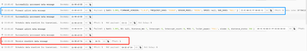
Users can use the downlink command(0x26 01) to ask DS20L to send device configure detail, include device configure status. DS20L will uplink a payload via FPort=5 to server.
The Payload format is as below.
Size(bytes) | 1 | 2 | 1 | 1 | 2 |
|---|---|---|---|---|---|
| Value | Sensor Model | Firmware Version | Frequency Band | Sub-band | BAT |
Example parse in TTNv3
Sensor Model: For DS20L, this value is 0x21
Firmware Version: 0x0100, Means: v1.0.0 version
Frequency Band:
0x01: EU868
0x02: US915
0x03: IN865
0x04: AU915
0x05: KZ865
0x06: RU864
0x07: AS923
0x08: AS923-1
0x09: AS923-2
0x0a: AS923-3
0x0b: CN470
0x0c: EU433
0x0d: KR920
0x0e: MA869
Sub-Band:
AU915 and US915:value 0x00 ~ 0x08
CN470: value 0x0B ~ 0x0C
Other Bands: Always 0x00
Battery Info:
Check the battery voltage.
Ex1: 0x0B45 = 2885mV
Ex2: 0x0B49 = 2889mV
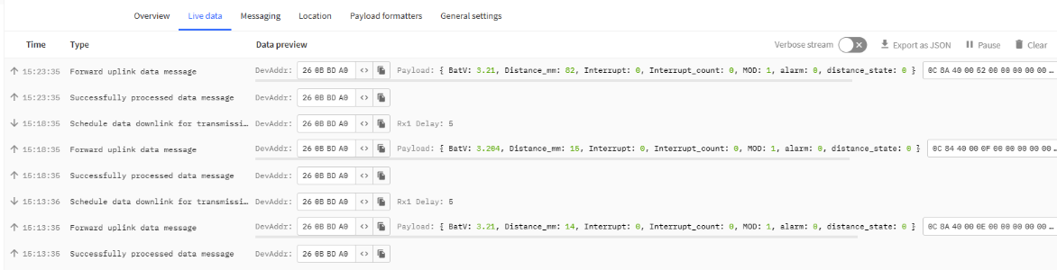
2.3.2 Uplink Payload, FPORT=2
AT+MOD=1
Regularly detect distance and report. When the distance exceeds the limit, the alarm flag is set to 1, and the report can be triggered by external interrupts.
Uplink Payload totals 10 bytes.
| Size(bytes) | 2 | 1 | 2 | 1 | 4 |
| Value | BAT | MOD+ Alarm+ Interrupt | Distance | Sensor State | Interrupt Count |
MOD+ Alarm+ Interrupt:
| Size(bit) | [bit7:bit6] | bit5 | bit4 |
| Value | MOD | Digital Interrupt | Distance Alarm 0: No Alarm; 1: Alarm |
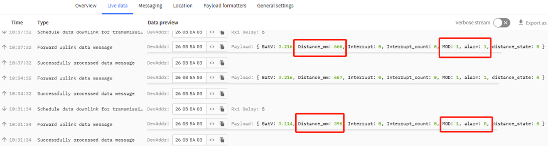
Example parse in TTNv3
Battery Info:
Check the battery voltage for DS20L
Ex1: 0x0E10 = 3600mV
MOD & Alarm & Interrupt:
MOD:
Example: (0x60>>6) & 0x3f =1
0x01: Regularly detect distance and report.
0x02: Uninterrupted measurement (external power supply).
Alarm:
When the detection distance exceeds the limit, the alarm flag is set to 1.
Interrupt:
Whether it is an external interrupt.
Distance info:
Example:
If payload is: 0708H: distance = 0708H = 1800 mm
Sensor State:
Ex1: 0x00: Distance Reading is valid
Ex2: 0x0x: Distance Reading is invalid
Interrupt Count:
If payload is:000007D0H: count = 07D0H =2000
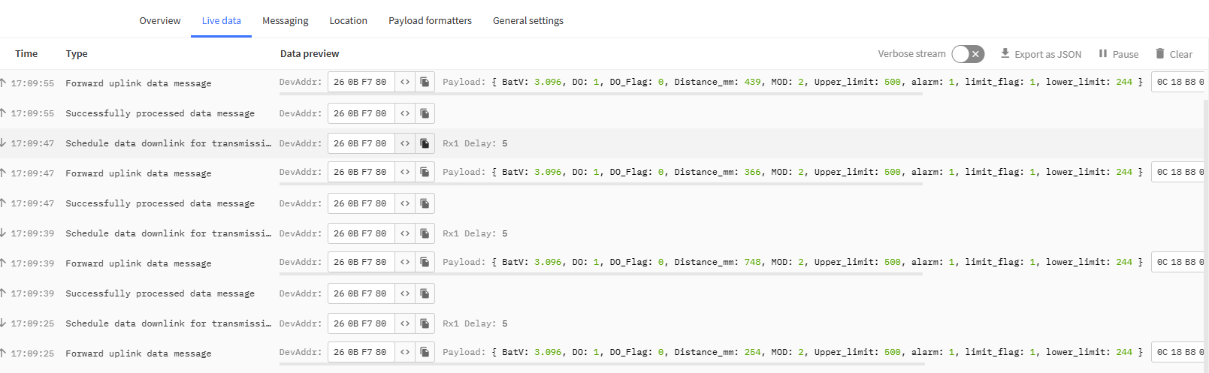
AT+MOD=2
The power consumption of uninterrupted measurement is high, and the device needs to use external power supply.(The switch is switched to E and the external power supply is used.)
- Set over-limit alarm mode: AT+DOL=3,500,244,0,120
Continuously measurement with Alarm. When the distance exceeds the limit, the output IO high, instant alarm.
Uplink Payload totals 9 bytes.
| Size(bytes) | 2 | 1 | 2 | 2 | 2 |
| Value | BAT | MOD+ DO+ Alarm+ DO flag+ Limit flag | Distance | Upper limit | Lower limit |
MOD+DO+ Alarm+ Do flag+ Limit flag:
| Size(bit) | [bit7:bit6] | bit5 | bit4 | bit3 | [bit2:bit1:bit0] |
| Value | MOD | DO 0:Within limit 1:Out of limit | Alarm 0: No Alarm; 1: Alarm | DO flag 0:the over-limit alarm mode 1:the person or object count mode | Limit flag (0~3) |
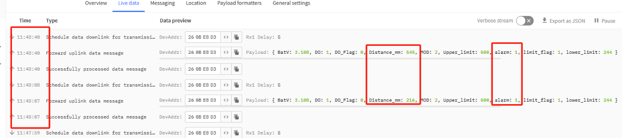
Example parse in TTNv3
MOD & Alarm & Do & Limit flag:
MOD:
Example: (0x60>>6) & 0x3f =1
0x01: Regularly detect distance and report.
0x02: Uninterrupted measurement (external power supply).
Alarm:
When the detection distance exceeds the limit, the alarm flag is set to 1.
DO:
Shows the DO pin status, while there is alarm trigger, The DO pin will be set to high (3.3v), It will be set to 0 low level when there is no alarm.
Threshold Flag for Alarm:
Mode for setting threshold: 0~3
0: Distance limit range is not enabled, alarm:0.
1: Trigger Alarm if distance exceed the range between lower and upper.
2: Trigger Alarm if distance smaller than the upper limit.
3: Trigger Alarm if distance bigger than the lower limit .
Distance:
Actual sampling distance values.
Example:
AT+DOL=1,500,244,0,120
The distance is detected every 120ms.
When the actual detection value is within the range of [244mm,500mm], the data is uploaded in the normal TDC time.
When the actual detection value is outside the range of [244mm,500mm], the uplink data will be immediately alerted.
If payload is: 0708H: distance = 0708H = 1800 mm
Upper limit:
Show the pre-set upper limit in Hex, Unit: mm.
Ex: 01F4(H)=500mm
Lower limit:
Show the pre-set lower limit in Hex, Unit: mm.
Ex: 0xF4(H)=244mm
- Set the person or object count mode: AT+DOL=1,500,244,1,120
Continuously measurement with Alarm, detect and count people or things passing by in distance limit mode.
Uplink Payload totals 11 bytes.
| Size(bytes) | 2 | 1 | 4 | 2 | 2 |
| Value | BAT | MOD+ DO+ Alarm+ DO flag+ Limit flag | Distance limit alarm count | Upper limit | Lower limit |
MOD+DO+ Alarm+ Do flag+ Limit flag:
| Size(bit) | [bit7:bit6] | bit5 | bit4 | bit3 | [bit2:bit1:bit0] |
| Value | MOD | DO 0:Within limit 1:Out of limit | Alarm 0: No Alarm; 1: Alarm | DO flag 0:the over-limit alarm mode 1:the person or object count mode | Limit flag (0~3) |
Example parse in TTNv3
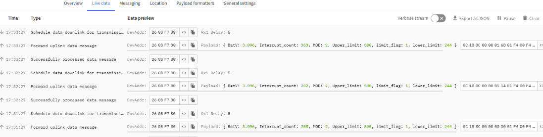
MOD & Alarm & Do & Limit flag:
MOD:
Example: (0x60>>6) & 0x3f =1
0x01: Regularly detect distance and report.
0x02: Uninterrupted measurement (external power supply).
Alarm:
When the detection distance exceeds the limit, the alarm flag is set to 1.
Do:
Shows the DO pin status, while there is alarm trigger, The DO pin will be set to high (3.3v), It will be set to 0 low level when there is no alarm.
Threshold Flag for Alarm:
Mode for setting threshold: 0~3
0: does not use upper and lower limits
1: Use upper and lower limits
2: Less than the upper limit
3: Greater than the lower limit
Distance limit alarm count:
People or objects are collected and counted within a limited distance.
The detection of a stationary person or object at each sampling time will be repeated three times, and the fourth sampling count will be added by 1.
Example:
AT+DOL=1,500,244,1,120
People or objects passing within the distance range of [244mm,500mm] are detected and counted every 120ms.
If payload is: 0x56H, interrupt count =0x56H =86
Upper limit:
Show the pre-set upper limit in Hex, Unit: mm.
Ex: 01F4(H)=500mm
Lower limit:
Show the pre-set lower limit in Hex, Unit: mm.
Ex: 0xF4(H)=244mm
2.4 Decode payload in The Things Network
While using TTN network, you can add the payload format to decode the payload.
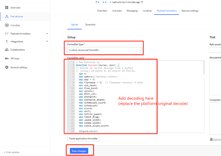
The payload decoder function for TTN is here:
DS20L TTN Payload Decoder: https://github.com/dragino/dragino-end-node-decoder
2.5 Show Data in DataCake IoT Server
DATACAKE provides a human friendly interface to show the sensor data, onhuman-friendlya in TTN, we can use DATACAKE to connect to TTN and see the data in DATACAKE. Below are the steps:
Step 1: Be sure that your device is programmed and properly connected to the network at this time.
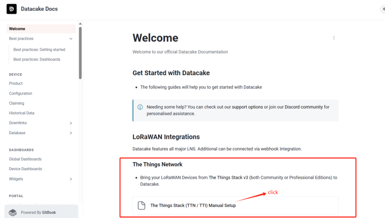
Step 2: To configure the Application to forward data to DATACAKE you will need to add integration. To add the DATACAKE integration, perform the following steps:
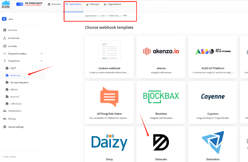
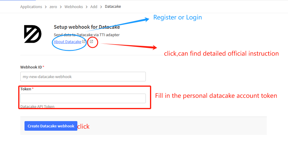
For more detailed instructions, refer to the following instructions: Welcome - Datacake Docs
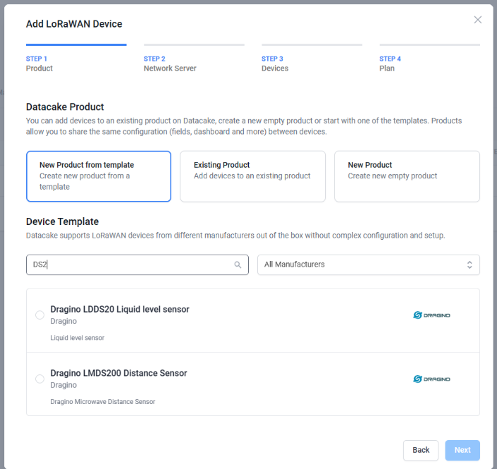
Step 3: Create an account or log in Datacake.
Step 4: Search the DS20L and add DevEUI.
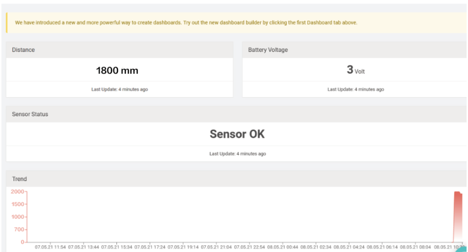
After added, the sensor data arrive TTN V3, it will also arrive and show in Datacake.
2.6 Frequency Plans
The DS20L uses OTAA mode and below frequency plans by default. If user want to use it with different frequency plan, please refer the AT command sets.
http://wiki.dragino.com/xwiki/bin/view/Main/End%20Device%20Frequency%20Band/
3. Configure DS20L
3.1 Configure Methods
DS20L supports below configure method:
- AT Command via UART Connection : See UART Connection.
- LoRaWAN Downlink. Instruction for different platforms: See IoT LoRaWAN Server section.
3.2 General Commands
These commands are to configure:
- General system settings like: uplink interval.
- LoRaWAN protocol & radio related command.
They are same for all Dragino Devices which support DLWS-005 LoRaWAN Stack. These commands can be found on the wiki:
http://wiki.dragino.com/xwiki/bin/view/Main/End%20Device%20AT%20Commands%20and%20Downlink%20Command/
3.3 Commands special design for DS20L
Below commands only valid for DS20L, as below:
3.3.1 Set Transmit Interval Time
Feature: Change LoRaWAN End Node Transmit Interval.
AT Command: AT+TDC
| Command Example | Function | Response |
|---|---|---|
| AT+TDC=? | Show current transmit Interval | 30000 |
| AT+TDC=60000 | Set Transmit Interval | OK |
Downlink Command: 0x01
Format: Command Code (0x01) followed by 3 bytes time value.
If the downlink payload=0100003C, it means set the END Node's Transmit Interval to 0x00003C=60(S), while type code is 01.
Example 1: Downlink Payload: 0100001E // Set Transmit Interval (TDC) = 30 seconds
Example 2: Downlink Payload: 0100003C // Set Transmit Interval (TDC) = 60 seconds
3.3.2 Set Interrupt Mode
Feature, Set Interrupt mode for pin of GPIO_EXTI.
When AT+INTMOD=0 is set, GPIO_EXTI is used as a digital input port.
AT Command: AT+INTMOD
| Command Example | Function | Response |
|---|---|---|
| AT+INTMOD=? | Show current interrupt mode | 0 |
AT+INTMOD=3 (default) | Set Transmit Interval | OK |
Downlink Command: 0x06
Format: Command Code (0x06) followed by 3 bytes.
This means that the interrupt mode of the end node is set to 0x000003=3 (rising edge trigger), and the type code is 06.
- Example 1: Downlink Payload: 06000000 // Turn off interrupt mode
- Example 2: Downlink Payload: 06000003 // Set the interrupt mode to rising edge trigger
3.3.3 Set work mode
Feature: Switch working mode
AT Command: AT+MOD
| Command Example | Function | Response |
|---|---|---|
| AT+MOD=? | Get the current working mode. | OK |
| AT+MOD=1 | Set the working mode to Regular measurements. | OK |
| AT+MOD=2 | Set the working mode to Continuously measurement with Alarm. | OK |
Downlink Command:
- Example: 0x0A01 // Same as AT+MOD=1
- Example: 0x0A02 // Same as AT+MOD=2
3.3.4 Set threshold and threshold mode
Feature, Set threshold and threshold mode
When AT+DOL=0,0,0,0,400 is set, No threshold is used, the sampling time is 400ms.
AT Command: AT+DOL
| Command Example | Function | Response |
| AT+ DOL =? | Get the current threshold mode and sampling time | 0,0,0,0,400 |
| AT+ DOL =1,1800,100,0,400 | Set only the upper and lower thresholds | OK |
| Command Example | Function | Parameter |
|---|---|---|
AT+DOL=1,1800,3,0,400 |
The first bit sets the limit mode | 0: Do not use upper and lower limits |
| 1: Use upper and lower limits | ||
| 2:Less than the upper limit | ||
| 3: Greater than the lower limit | ||
| The second bit sets the upper limit value | 3~2000MM | |
| The third bit sets the lower limit value | 3~2000MM | |
| The fourth bit sets the over-limit alarm or person or object count. | 0 Over-limit alarm, DO output is high | |
| 1 Person or object counting statistics | ||
| The fifth bit sets the sampling time | 100~10000ms
|
Downlink Command: 0x07
Format: Command Code (0x07) followed by 9 bytes.
If the downlink payload=07 01 0708 0064 00 0190, it means set the END Node's limit mode to 0x01,upper limit value to 0x0708=1800(mm), lower limit value to 0x0064=100(mm), to over-limit alarm(0x00) ,the sampling time to 0x0190=400(ms), while type code is 0x07.
- Example 0: Downlink Payload: 07 00 0000 0000 00 0190 ---> AT+MOD=0,0,0,0,400
- Example 1: Downlink Payload: 070107080064000190 ---> AT+MOD=1,1800,100,0,400
- Example 2: Downlink Payload: 070200000064000190 ---> AT+MOD=2,1800,100,0,400
- Example 3: Downlink Payload: 070300000064000190 ---> AT+MOD=3,0,100,0,400
Note: The over-limit alarm is applied to MOD1 and MOD2.
For example:
- AT+MOD=1
AT+DOL=1,500,244,0,300
Send data according to the normal TDC time. If the mode limit is exceeded, the alarm flag is set to 1:
- AT+MOD=2
AT+DOL=1,500,244,0,300
If the mode limit is exceeded, the data is immediately uplink and the alarm flag is set to 1:
4. Battery & Power Consumption
DS20L use built-in 2400mAh non-chargeable battery for long-term use up to several years*. See below link for detail information about the battery info and how to replace.
Battery Info & Power Consumption Analyze .
5. OTA Firmware update
User can change firmware DS20L to:
- Change Frequency band/ region.
- Update with new features.
- Fix bugs.
Firmware and changelog can be downloaded from : Firmware download link
Methods to Update Firmware:
- (Recommanded way) OTA firmware update via wireless: http://wiki.dragino.com/xwiki/bin/view/Main/Firmware%20OTA%20Update%20for%20Sensors/
- Update through UART TTL interface: Instruction.
6. FAQ
6.1 What is the frequency plan for DS20L?
DS20L use the same frequency as other Dragino products. User can see the detail from this link: Introduction
6.2 DS20L programming line
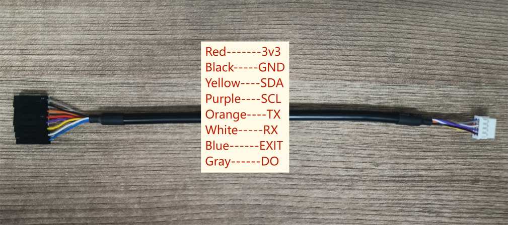
feature:
for AT commands
Update the firmware of DS20L
Support interrupt mode
6.3 LiDAR probe position
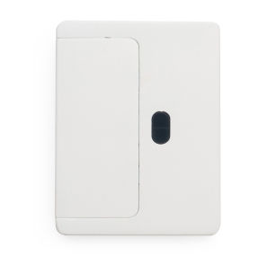
The black oval hole in the picture is the LiDAR probe.
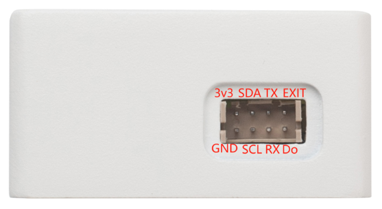
6.4 Interface definition
7. Trouble Shooting
7.1 AT Command input doesn't work
In the case if user can see the console output but can't type input to the device. Please check if you already include the ENTER while sending out the command. Some serial tool doesn't send ENTER while press the send key, user need to add ENTER in their string.
7.2 Significant error between the output distant value of LiDAR and actual distance
Cause ①:Due to the physical principles of The LiDAR probe, the above phenomenon is likely to occur if the detection object is the material with high reflectivity (such as mirror, smooth floor tile, etc.) or transparent substance. (such as glass and water, etc.)
Troubleshooting: Please avoid use of this product under such circumstance in practice.
Cause ②: The IR-pass filters are blocked.
Troubleshooting: please use dry dust-free cloth to gently remove the foreign matter.
8. Order Info
Part Number: DS20L-XXX
XXX: The default frequency band
- AS923: LoRaWAN AS923 band
- AU915: LoRaWAN AU915 band
- EU433: LoRaWAN EU433 band
- EU868: LoRaWAN EU868 band
- KR920: LoRaWAN KR920 band
- US915: LoRaWAN US915 band
- IN865: LoRaWAN IN865 band
- CN470: LoRaWAN CN470 band
9. Packing Info
Package Includes:
- DS20L LoRaWAN Smart Distance Detector x 1
Dimension and weight:
- Device Size: cm
- Device Weight: g
- Package Size / pcs : cm
- Weight / pcs : g
10. Support
- Support is provided Monday to Friday, from 09:00 to 18:00 GMT+8. Due to different timezones we cannot offer live support. However, your questions will be answered as soon as possible in the before-mentioned schedule.
- Provide as much information as possible regarding your enquiry (product models, accurately describe your problem and steps to replicate it etc) and send a mail to Support@dragino.cc.