WGT-11 LoRaWAN Indoor Gateway User Manual
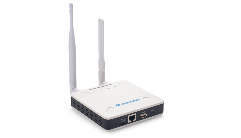
Table of Contents:
- 1. Introduction
- 2. Quick Start
- 3. Web Configure Pages
- 4. Build-in Server
- 5. How the WGT-11 connects to Chirpstack via gateway-bridge
- 6. How users can access WGT-11 using serial USB
- 7. Use the helium gateway-rs as the Data-only Hotspot
- 8. OTA System Update
- 9. Trouble Shooting
- 10. Supports
- 11. Reference
- 12. Order Info
- 13. Manufacturer Info
- 14. FCC Warning
1. Introduction
1.1 What is WGT-11
The WGT-11 is an open-source LoRaWAN Gateway. It lets you bridge LoRa wireless network to an IP network via WiFi , Ethernet or Cellular Network (via Optional 4G module). The LoRa wireless allows users to send data and reach extremely long ranges at low data rates.
The WGT-11 is fully compatible with LoRaWAN protocol. It supports different kinds of LoRaWAN Network Connections such as: Semtech UDP Packet Forwarder, LoRaWAN Basic Station, ChirpStack MQTT Bridge, and so on. This makes WGT-11 work with most LoRaWAN platforms in the market.
WGT-11 also includes a built-in LoRaWAN Server and IoT server, which provide the possibility for the system integrator to deploy the IoT service without cloud service or 3rd servers.
Different countries use different LoRaWAN frequency bands. WGT-11 has these bands pre-configured. Users can also customize the frequency bands to use in their own LoRa network.
WGT-11 supports remote management. System Integrator can easy to remote monitor the gateway and maintain it.
1.2 Specifications
Hardware System:
- CPU: Quad-core Cortex-A7 1.2Ghz
- RAM: 512MB
- eMMC: 4GB
Interface:
- 10M/100M RJ45 Ports x 1
- Multi-Channel LoRaWAN Wireless
- WiFi 802.11 b/g/n
- Sensitivity: -140dBm
- Max Output Power: 27dBm
Operating Condition:
- Work Temperature: -20 ~ 70°C
- Storage Temperature: -20 ~ 70°C
- Power Input: 5V, 2A, DC
1.3 Features
- Open Source Debian system
- Managed by Web GUI, SSH via WAN or WiFi
- Remote Management
- Auto-provisioning for batch deployment and management
- LoRaWAN Gateway
- 10 programmable parallel demodulation paths
- Pre-configured to support different LoRaWAN regional settings.
- Allow customizing LoRaWAN regional parameters.
- Different kinds of LoRaWAN Connections such as
- Semtech UDP Packet Forwarder
- LoRaWAN Basic Station
- ChirpStack-Gateway-Bridge (MQTT)
- Built-in The Things Network local LoRaWAN server
- Built-in Node-Red local Application server
1.4 Block Diagram
1.5 LED Indicators
WGT-11 has totally four LEDs, They are:
➢ Power LED: This RED LED will be solid if the device is properly powered
➢ ETH LED: This RGB LED will blink GREEN when the ETH port is connecting
➢ SYS LED: This RGB LED will show different colors in different states:
✓ SOLID GREEN: The device is alive with a LoRaWAN server connection.
✓ BLINKING GREEN: a) Device has internet connection but no LoRaWAN Connection. or b) Device is in booting stage, in this stage, it will BLINKING GREEN for several seconds and then with BLINKING GREEN together
✓ SOLID RED: Device doesn't have an Internet connection.
➢ WIFI LED: This LED shows the WIFI interface connection status.
1.6 Button Intruction
WGT-11 has a black toggle button, which is:
➢ Long press 4-5s : the gateway will reload the Network and Initialize wifi configuration
LED status: ETH LED will BLINKIND BULE Until the reload is finished.
➢ Long press more than 10s: the gateway will restore the factory settings.
LED status: ETH LED will SOLID BULE Until the restore is finished.
2. Quick Start
The WGT-11 supports network access via Ethernet or Wi-Fi connection and runs without a network.
In most cases, the first thing you need to do is make the WGT-11 accessible to the network.
2.1 Connects to the network and accesses the gateway Web UI
2.1.1 connect the network
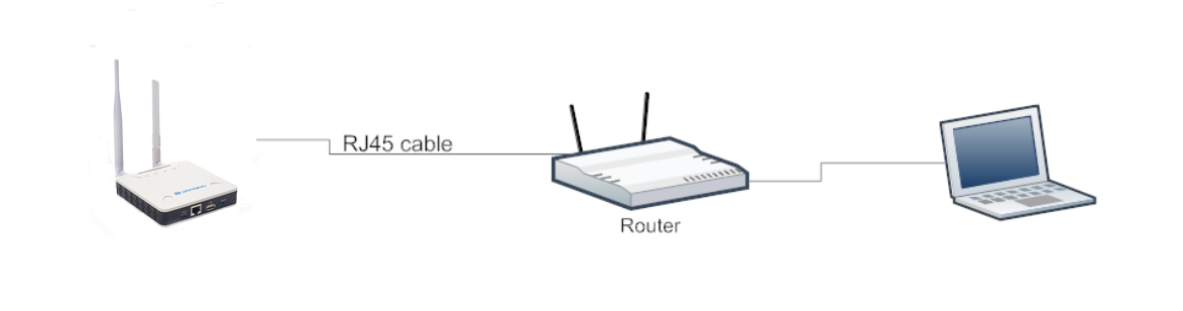
Method 1: Connect via Ethernet with DHCP IP from the router
Connect the WGT-11 Ethernet port to your router and WGT-11 can obtain an IP address from your router. In the router's management portal, you should be able to find what IP address the router has assigned to the WGT-11.
You can also use this IP to connect.
Method 2: Connect via WGT-11 Fallback IP
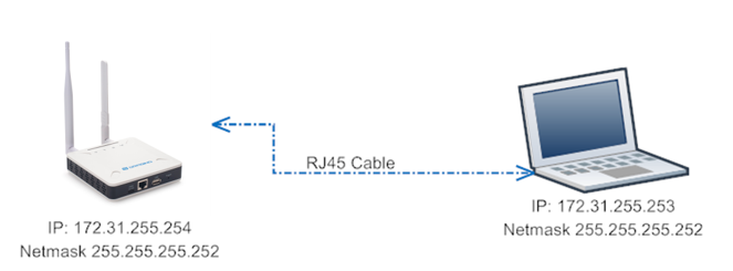
Steps to connect via fallback IP:
1. Connect the PC's Ethernet port to WGT-11's WAN port
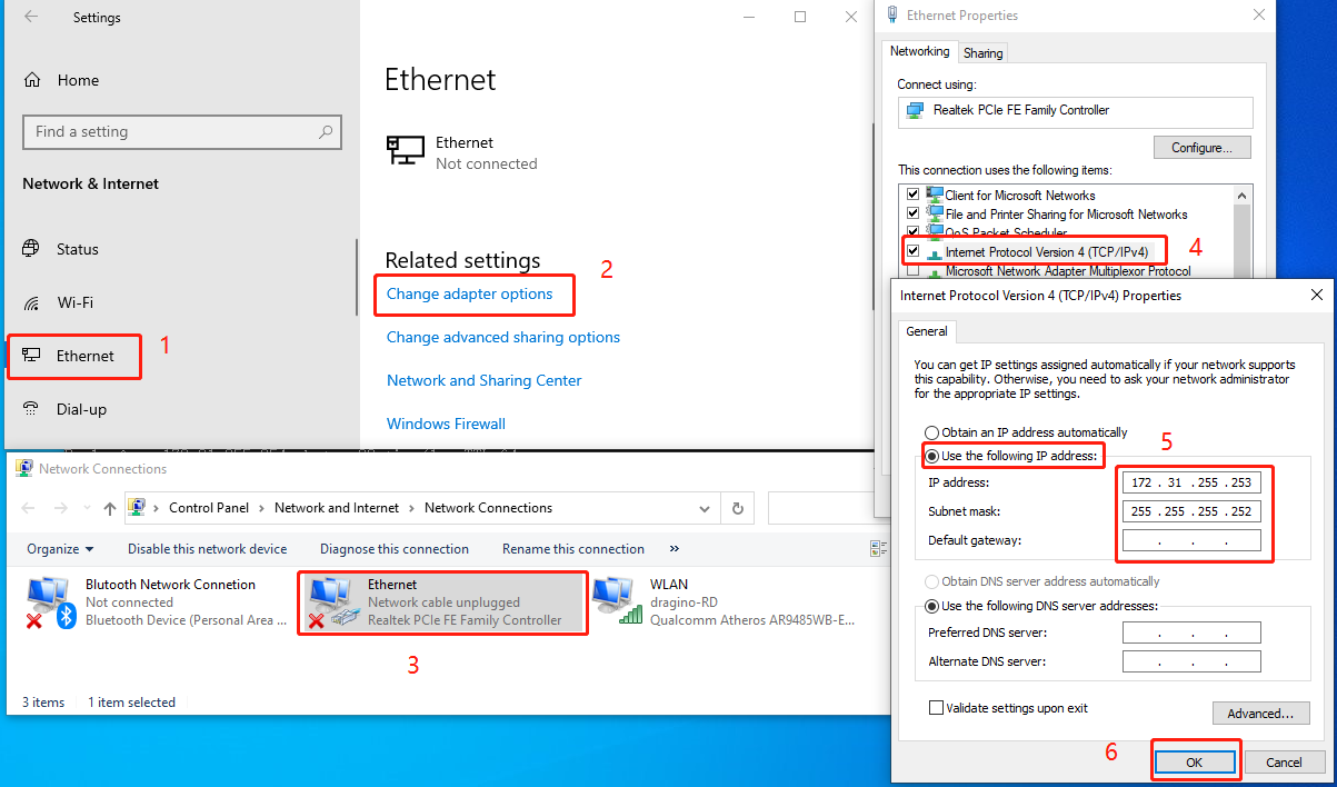
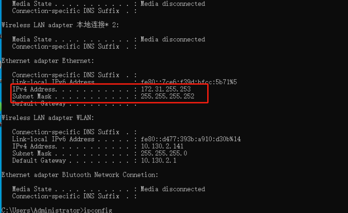
2. Configure PC's Ethernet port has IP: 172.31.255.253 and Netmask: 255.255.255.252
Settings --> Network & Internet --> Ethernet --> Change advanced sharing options --> Double-click"Ethernet" --> Internet Protocol Version 4 (TCP/IPv4)
As in the below photo:
Configure computer Ethernet port steps video:
If you still can't access the WGT-11 fallback ip, follow this connection to debug :Trouble Shooting
3. In the PC, use IP address 172.31.255.254 to access the WGT-11 via Web or Console.
Method 3: Connect via WiFi with DHCP IP from the router
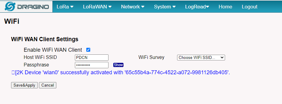
Fill in the WiFi information by checking the box and clicking Save&Apply
Wi-Fi configuration successful
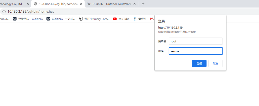
2.1.2 Access Configure Web UI
Web Interface
Open a browser on the PC and type the WGT-11 ip address (depends on your connect method)
http://IP_ADDRESS or http://172.31.255.254(Fallback IP)
You will see the login interface of WGT-11 as shown below.
The account details for Web Login are:
User Name: root
Password: dragino
2.2 Typical Network Setup
2.2.1 Overview
WGT-11 supports flexible network set up for different environment. This section describes the typical network topology can be set in WGT-11. The typical network set up includes:
- WAN Port Internet Mode
- WiFi Client Mode
- Cellular Mode
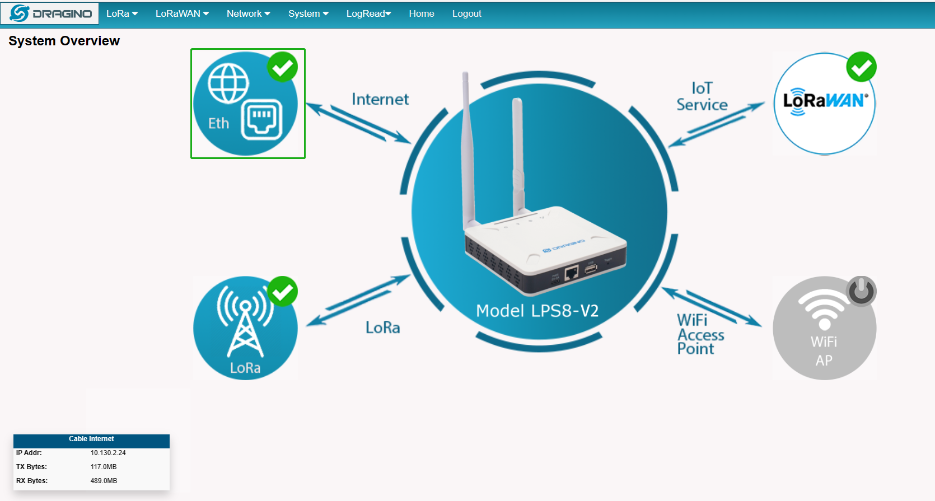
2.2.2 Use WAN port to access Internet
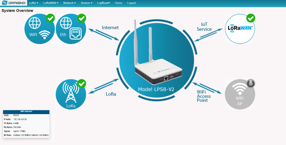
By default, the WGT-11 is set to use the WAN port to connect to an upstream network. When you connect the WGT-11's WAN port to an upstream router, WGT-11 will get an IP address from the router and have Internet access via the upstream router. The network status can be checked in the home page:
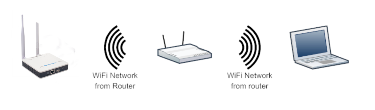
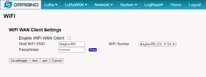
2.2.3 Access the Internet as a WiFi Client
In the WiFi Client Mode, WGT-11 acts as a WiFi client and gets DHCP from an upstream router via WiFi.
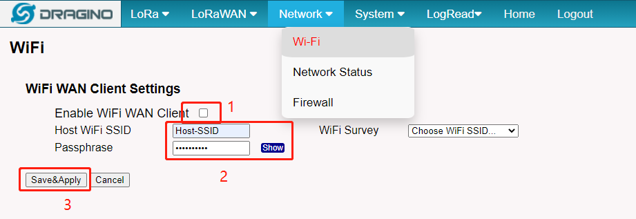
The settings for WiFi Client is under page Network --> Wi-Fi
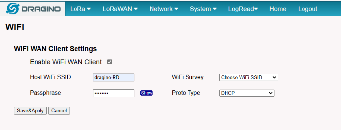
In the WiFi Survey Choose the WiFi AP, and input the Passphrase then click Save & Apply to connect.
2.2.4 Use built-in 4G modem for internet access
Since Hardware version HP0C 1.4
Users can see whether WGT-11 has EC25 on the label of the gateway to determine whether there is 3G/4G Cellular modem.
If the WGT-11 has 3G/4G Cellular modem, user can use it as main internet connection or back up.
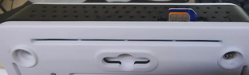
First, install the Micro SIM card as below direction
Second, Power off/ ON WGT-11 to let it detect the SIM card.
The set up page is Network --> Cellular
While use the cellular as Backup WAN, device will use Cellular for internet connection while WAN port or WiFi is not valid and switch back to WAN port or WiFi after they recover.
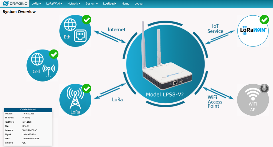
2.2.5 Check Internet connection
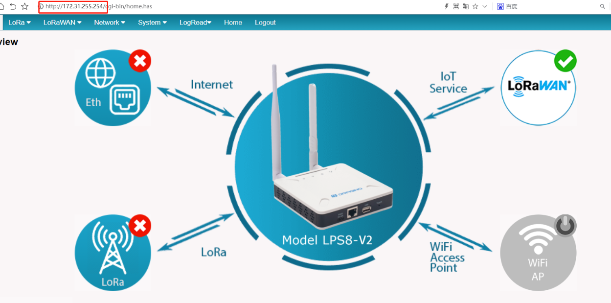
In the home page, we can check the Internet connection.
- GREEN Tick
 : This interface has Internet connection.
 - Yellow Tick
 : This interface has IP address but don't use it for internet connection.
 - RED Cross
 : This interface doesn't connected or no internet.
2.3 The WGT-11 is registered and connected to The Things Network
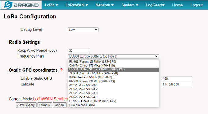
2.3.1 Select your area frequency
First, you need to set the frequency plan in WGT-11 to match the end node we use, so to receive the LoRaWAN packets from the LoRaWAN sensor.
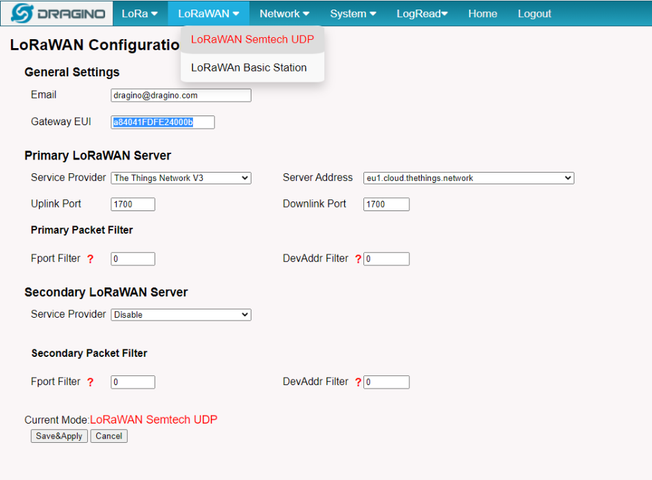
2.3.2 Get the only gateway EUI
Every WGT-11 has a unique gateway id. The ID can be found on LoRaWAN Semtech page:
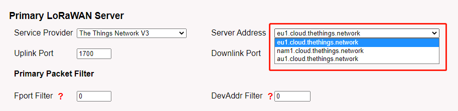
Note: Choose the cluster that corresponds to a specific Gateway server address
➢ Europe 1: corresponding Gateway server address: eu1.cloud.thethings.network
➢ North America 1: corresponding Gateway server address: nam1.cloud.thethings.network
➢ Australia 1: corresponding Gateway server address: au1.cloud.thethings.network
➢ Legacy V2 Console: TTN v2 shuts down in December 2021
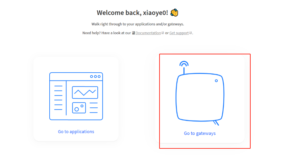
2.3.3 Register the gateway to The Things Network
Login to The Things Network
https://console.cloud.thethings.network/
Add the gateway
Get it online
3. Web Configure Pages
3.1 Home
Shows the system running status:

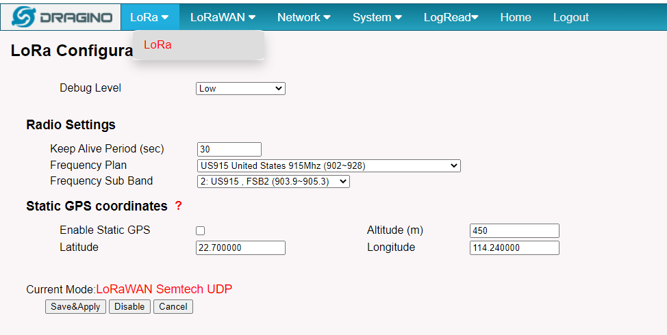
3.2 LoRa Settings
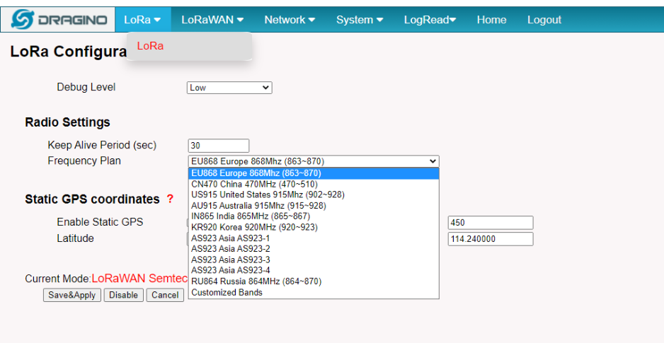
3.2.1 LoRa --> LoRa
This page shows the LoRa Radio Settings. There is a set of default frequency bands according to LoRaWAN protocol, and users can customize the band* as well.
Different WGT-11 hardware versions can support different frequency ranges:
- 868: valid frequency: 863Mhz ~ 870Mhz. for bands EU868, RU864, IN865, or KZ865.
- 915: valid frequency: 902Mhz ~ 928Mhz. for bands US915, AU915, AS923 or KR920
After the user choose the frequency plan, the user can see the actual frequency is used by checking the page LogRead --> LoRa Log
Note *: See this instruction for how to customize the frequency band: How to customized LoRaWAN frequency band - DRAGINO
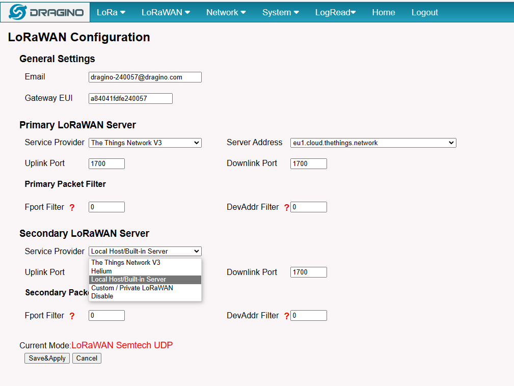
3.3 LoRaWAN Settings
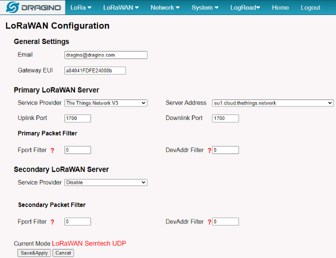
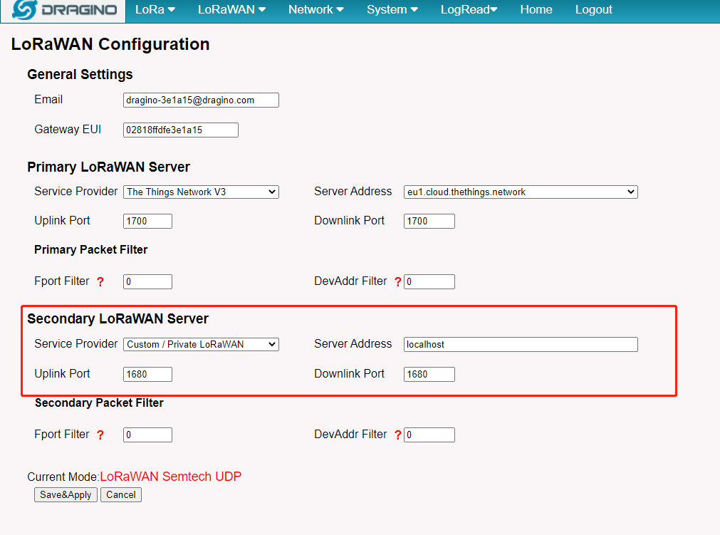
3.3.1 LoRaWAN --> LoRaWAN Semtech UDP
This page is for the connection set up to a general LoRaWAN Network server such as TTN, ChirpStack, etc.
3.3.2 LoRaWAN --> LoRaWAN Basic Station
This page is for the connection set up to the TTN Basic Station, AWS-IoT, etc.
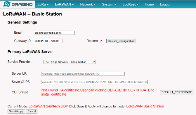
Please see this instruction to know more detail and a demo for how to use of LoRaWAN Basic Station: Use of LoRaWAN Basic Station - DRAGINO
3.4 Network Settings
3.4.1 Network --> WiFi
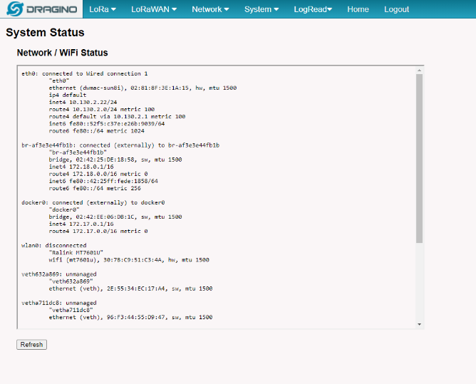
3.4.2 Network --> System Status
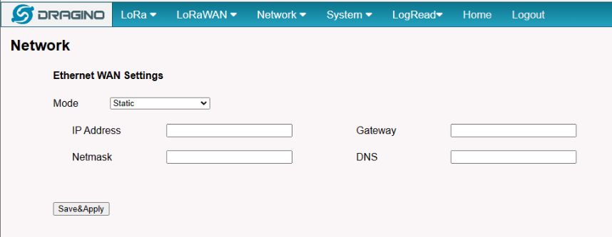
3.4.3 Network --> Network
In the Network --> Network interface, Users can set the Ethernet WAN static ip address.
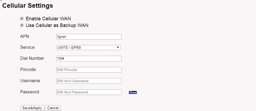
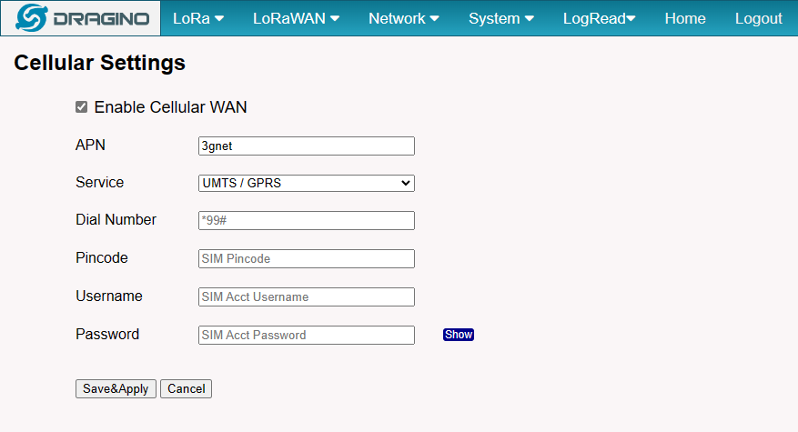
3.4.4 Network --> Cellular
In the Network --> Cellular interface, Users can Enable Cellular WAN and configure Celluar.
Note: APN cannot be empty.
After the configuration is complete, return to the Home interface and put the mouse on the Cell icon to check the Cellualr state.
3.5 System
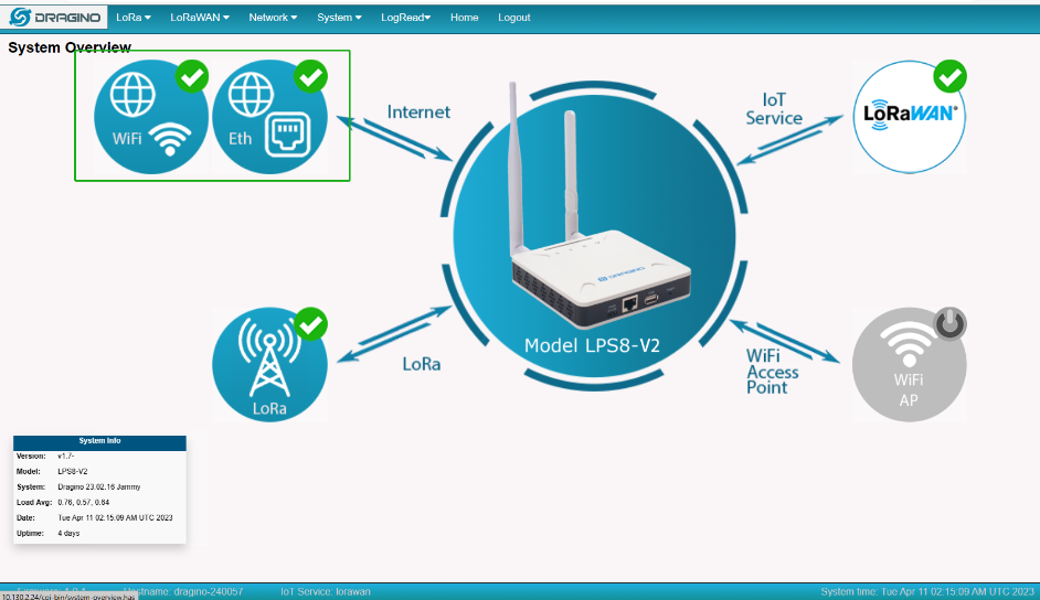
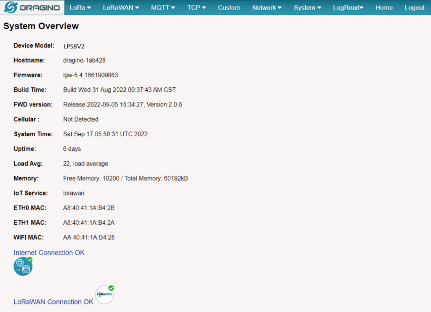
3.5.1 System --> System Overview
Shows the system info:
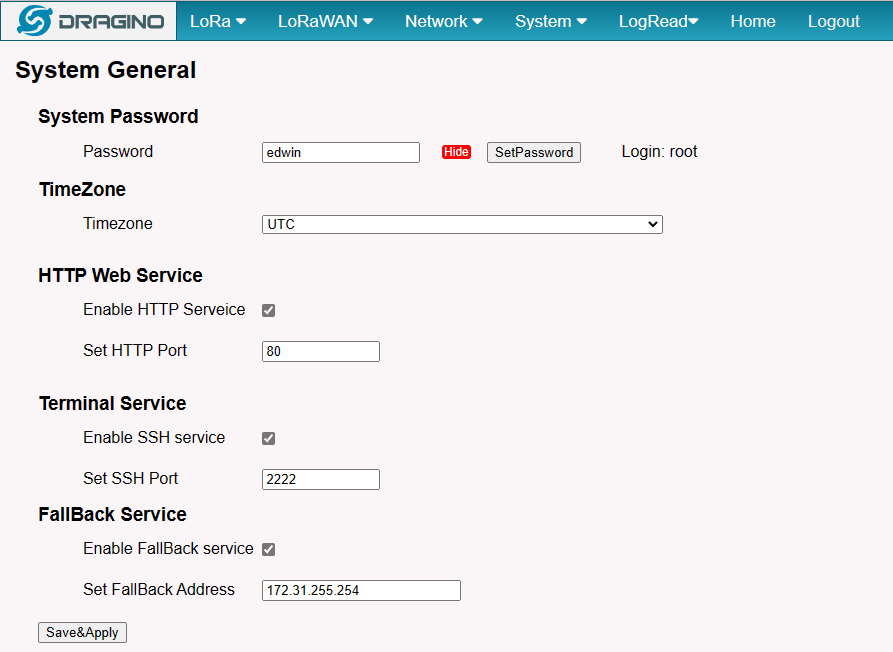
3.5.2 System --> System General
In the System-> System General interface, Users can customize the configuration System Password and set Timezone.
In addition, Users can customize the FallBack IP address.
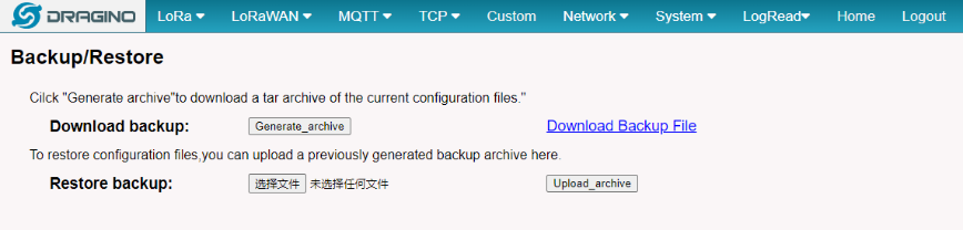
3.5.3 System --> Backup/Restore
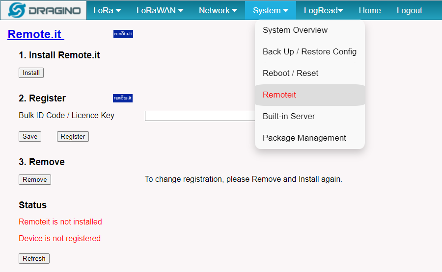
3.5.4 System --> Remoteit
In the System-> Remoteit interface, users can configure the gateway to be accessed remotely via Remote.it.
the users can refer to this link to configure them: Monitor & Remote Access Gateway
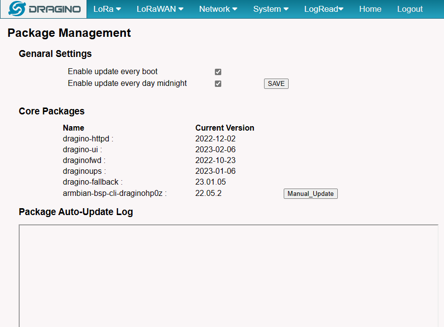
3.5.5 System --> Package Management
In the System --> Package Management interface, Users can check the current version of Core Packages.
4. Build-in Server
The default factory version of WGT-11 is installed with the built-in Applicant server: Node-Red, and LoRaWAN Server: The Things Network - Stack (Open Source 3.19 Version).
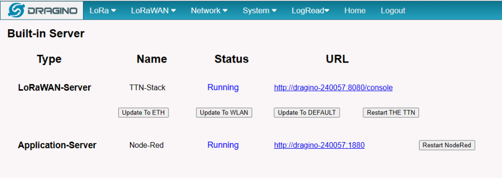
Note:
Path: System --> Built-in Server
Troubleshooting:
1. URL does not jump properly
For the ttn-stack, you can click the update the URL which will update the configuration where change the hostname to the current local IP address as the URL.
For the Node-Red, you can use the local IP address and the port is 1880 to access it.
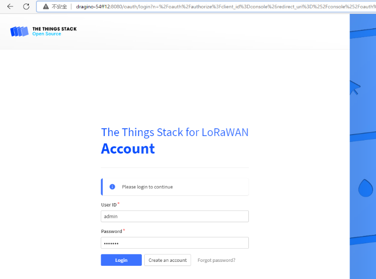
4.1 LoRaWAN Network Server -- The Things Network - Stack (TTN-V3)
You can access the gateway's built-in LNS server of The Things Network - Stack via the URL( http://<hostname>:8080 or http://<local-IPV4-address> ) in your browser.
Such as http://dragino-54ff12:8080 or http://<Local-IPV4-Address>
Login account:
User ID: admin
Password: dragino
4.1.1 The WGT-11 is registered and connected to Built-in The Things Network
Users need to set the Service Provider to Local Host/Build-in Server and click "Save&Apply"
The registration steps are basically similar to WGT-11 is registered and connected to The Things Network
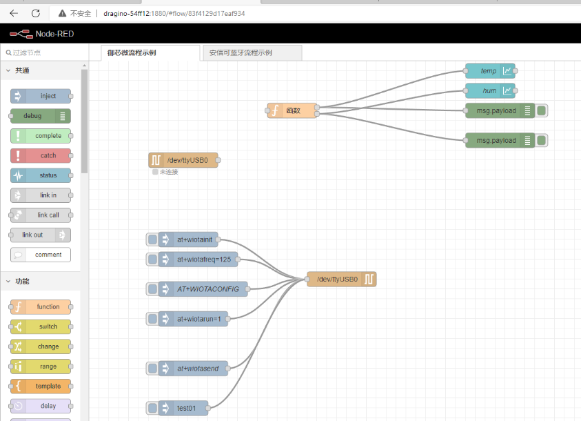
4.2 Application Server -- Node-Red
You can access the gateway's built-in AS server of Node-Red via the URL(http://<hostname>:1880 or http://<local-IPV4-address>) in your browser.
Such as http://dragino-54ff12:1880 or http://<Local-IPV4-Address>
Using Node-Red, InfluxDB and Grafana
The WGT-11 supports this combination, the default, Node-red is pre-installed but the InfluxDB and Grafana is not pre-installed.
the users can refer to this link to install them.
Upgrade the node.js
By default, the WGT-11 node.js uses the pre-install version v12 which is due to Debian the ultra-stable via ultra-old.
the users can refer to this link to upgrade them.
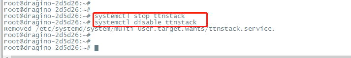
4.3 How to disable the built-in server
Use the following commands to start and stop the TTNv3 service:
Use the following commands to start and stop the Node-Red service:
4.4 How to use ChirpStack on WGT-11
By default, the built-in LoRaWAN network server used on WGT-11 is TTNv3, so users need to disable TTNv3 services and follow this link to install chirpstack:
ChirpStack open-source LoRaWAN® Network Server documentation
5. How the WGT-11 connects to Chirpstack via gateway-bridge
6. How users can access WGT-11 using serial USB
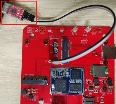
USB TTL to WGT-11 Connection:
Port 1 of the UART on the WGT-11 is GND
WGT-11 UART connection photo
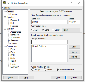
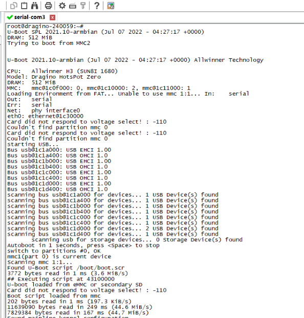
In the PC,you can use the serial port tool(such as putty in Windows), you need to set the serial baud rate to 115200 to access the serial console for WGT-11. WGT-11 will output system info once power on as below:
7. Use the helium gateway-rs as the Data-only Hotspot
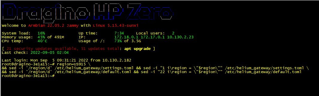
Step 1: Configure Frequency Band
Each country has a requirement for frequency region. Choose the right one for your area.
Step 2: Configure the forward address
Select one of the servers to configure.
For example:
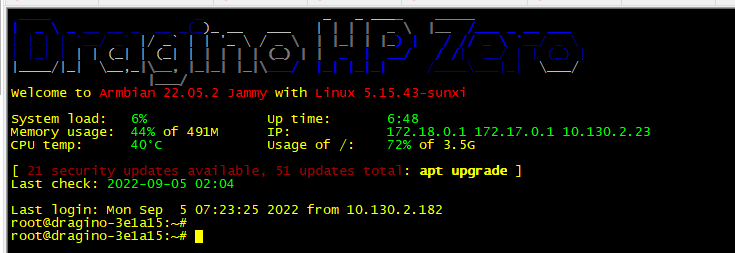
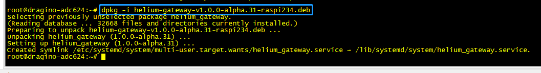
Step 3: Download and Install the Helium-gateway-rs
Access the gateway CLI via SSH.
Download gateway-rs.
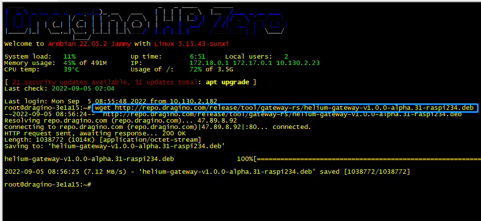
Install gateway-rs.
Modify configuration.
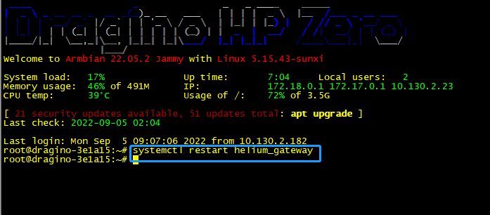
Restart the helium_gateway
Check the helium_gateway Log:
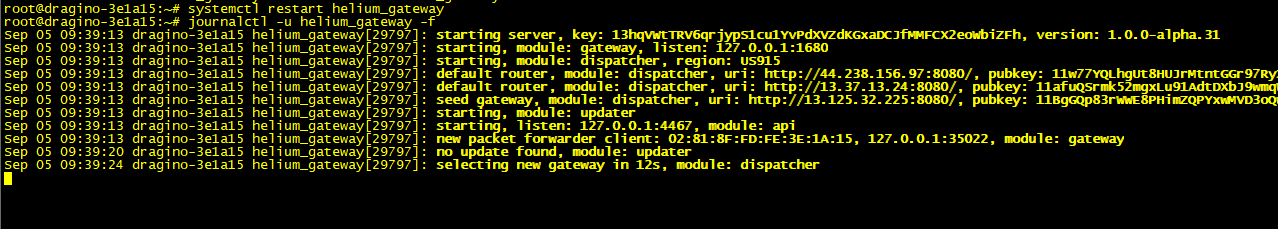
Note: if your device is not finished the onboarding, which is unable to connect to the Helium console.
where the helium gateway log is shown:
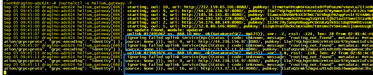
So you have to finish the onboarding, ---Please refer to Step 2.7 to onboarding your WGT-11.
8. OTA System Update
WGT-11 supports system auto update via OTA, please see this URL for the detail of this feature.
9. Trouble Shooting
9.1 I can't log in to the built-in Server TTN Stack which shows 'Login failed'.
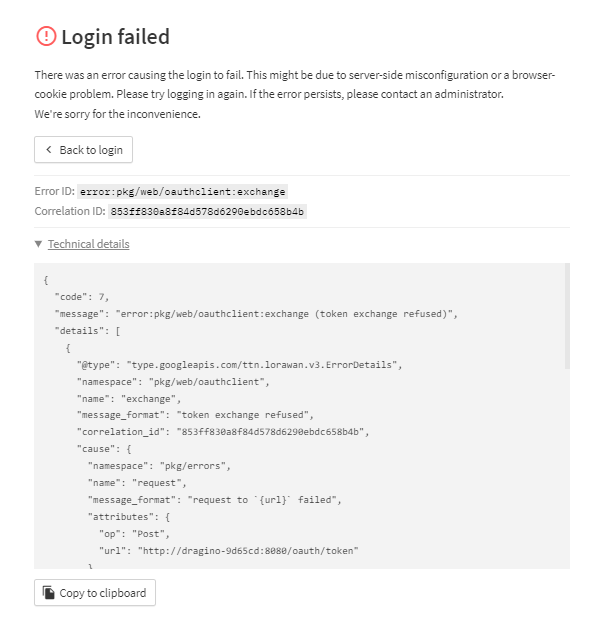
This is caused by the inconsistency between the built-in TTN-Stack domain configuration and your login URL.
By default, ttn-stack uses the gateway's domain name for URL resolution, but in some networks, they prefer to resolve IP-v4 addresses.
So you can change the domain name of the TTN-Stack configuration to the IPv4 address.
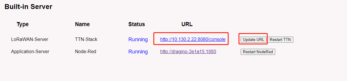
Click the update URL button to configure the URL with the current eth port address.
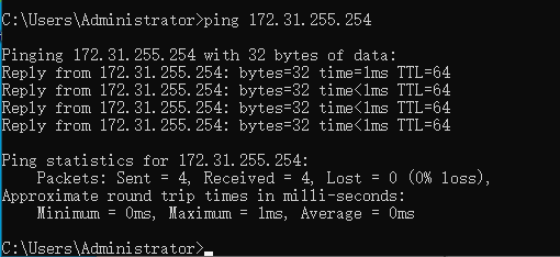
9.2 Fallback IP does not work, how can users check
When the computer has completed the above fallback IP configuration,the WGT-11 Web UI is still not accessible via fallback IP.
1.Check whether the configuration is correct
Run the CMD command to ipconfig and ping 172.31.255.254.
If this fails, the user needs to reconfigure.
2. Check whether the firewall is disabled
If the firewall is not down, this will affect access to the gateway.
10. Supports
If you are experiencing issues and can't solve them, you can send mail to support@dragino.com.
With your question as detailed as possible. We will reply and help you in the shortest.
11. Reference
- Install Tago Core: Refer Install Tago Core in WGT-11 in Instruction.
- Advance OS Reference Guide for WGT-11.
12. Order Info
WGT-11-XXX-YYY
XXX: Frequency Band
- AS923: LoRaWAN AS923 band
- AU915: LoRaWAN AU915 band
- EU868: LoRaWAN EU868 band
- KR920: LoRaWAN KR920 band
- US915: LoRaWAN US915 band
- IN865: LoRaWAN IN865 band
YYY: 4G Cellular Option
- E: EMEA, Korea, Thailand, India.
- A: North America/ Rogers/AT&T/T-Mobile.
- AU: Latin America, New Zeland, Taiwan
- J: Japan, DOCOMO/SoftBank/ KDDI
More info about valid bands, please see EC25-E product page.
13. Manufacturer Info
Shenzhen Dragino Technology Development co. LTD
Room 202, Block B, BCT Incubation Bases (BaoChengTai), No.8 CaiYunRoad
LongCheng Street, LongGang District ; Shenzhen 518116,China
14. FCC Warning
This equipment has been tested and found to comply with the limits for a Class B digital device, pursuant to Part 15 of the FCC Rules. These limits are designed to provide reasonable protection against harmful interference in a residential installation. This equipment generates uses and can radiate radio frequency energy and, if not installed and used in accordance with the instructions, may cause harmful interference to radio communications. However, there is no guarantee that interference will not occur in a particular installation. If this equipment does cause harmful interference to radio or television reception, which can be determined by turning the equipment off and on, the user is encouraged to try to correct the interference by one or more of the following measures:
-- Reorient or relocate the receiving antenna.
-- Increase the separation between the equipment and receiver.
-- Connect the equipment into an outlet on a circuit different from that to which the receiver is connected.
-- Consult the dealer or an experienced radio/TV technician for help.
Changes or modifications not expressly approved by the party responsible for compliance could void the user's authority to operate the equipment.
The antenna(s) used for this transmitter must be installed to provide a separation distance of at least 20 cm from all persons and must not be co-located or operating in conjunction with any other antenna or transmitter.