How to improve LoRaWAN distance
Table of Contents:
- 1. OverView
- 2. Analyze at the software side
- 3. Analyze at the hardware side
- 4. Installation Guidelines
- 5. Some real-world case
- 6. Use a repeater
1. OverView
In real-world deployment for LoRa, distance is a common topic. We always want to have the longest distance. This chapter shows some instructions for how to improve this.
2. Analyze at the software side
2.1 LoRa parameters that effect distance
Some settings in End Node will affect the transfer distance. They are:
- TXPower: This means the output power from End Node. There is a command AT+TXP can be used to set the output power. TXP parameters follow the LoRaWAN regional document (rp2-1.0.3-lorawan-regional-parameters.pdf). Set to AT+TXP=0 is always has the maximum output, but AT+TXP=0 has different value in different frequency bands.
- Data Rate(DR): This is a combination of Spreading Factor and Band Width. Lowest Data Rate (DR=0) always has the longest transmit distance in LoRaWAN protocol.
Below is the TXPower and DR table of EU868 Frequency band as reference.
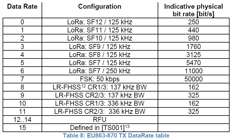
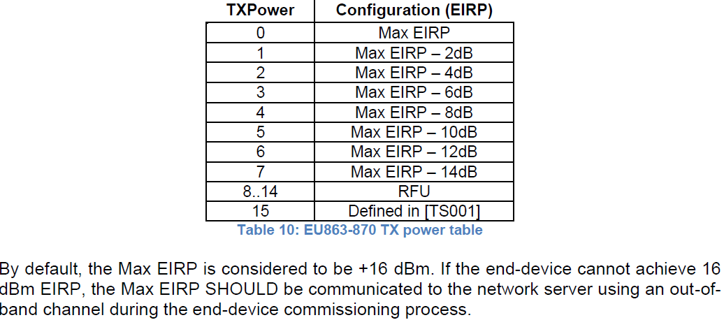
Set AT+TXP=0 and AT+DR=0 will always has the longest transmit distance. But note that different frequency band has different TXP and DR coding according to LoRaWAN regional settings. Below is example for EU868, US915 and AS923 compare for example.
End node actually value when TXP=0 and DR=0
| Frequency band | Output Power in LoRa Module (consider 2dB antenna) | Spreading Factor(Higher SF can transmit further) | Band Width |
| EU868 | 14dBm | SF=12 | 125Khz |
| US915 | 20 or 22 dBm (depends on max output of module) | SF=10 | 125Khz |
| AS923 | 14dBm | SF=12 | 125Khz |
2.2 Adaptive Data Rate (ADR) and set max distance
ADR is the feature that Server will ask End Node to adjust the TXP and DR according to some rules in the server. This is for the purpose of Network Management and Optimize End Node battery life-time.
By default, ADR is turn on(AT+ADR=1) so End node ADR feature is enable.
Normally, user can set the max distance by setting:
AT+ADR=0
AT+DR=0 // Use longest distance modulation
AT+TXP=0 // Use max power For EU868, max power can be is AT+TXP=50
This can be downlink via the LoRaWAN downlink command, see this link for reference.
2.3 Check for short distance problem
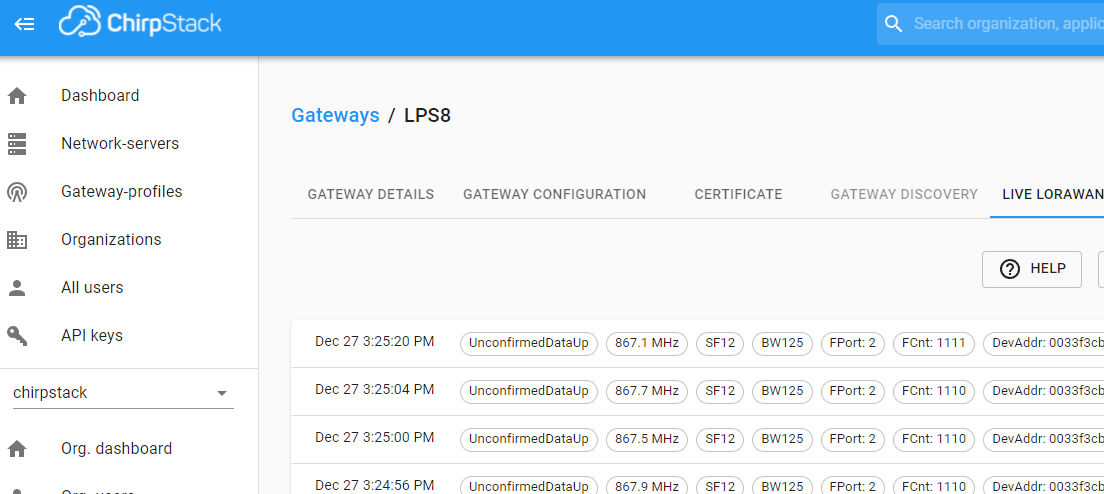
According to the above technology, if we have a problem on the distance, we can first check if the end node is trying to longest distance modulation already. We can see that from the LoRaWAN server. Below is an example from Chirpstack.
We can see the traffic in gateway's page and know that the distance is SF12 / BW125. (note, server is not able to know Transmit Power settings from End Node)
2.4 Best software settings for the longest distance
Below are the settings for longest distance transmission. ( will reduce battery life)
- AT+ADR=0 // Disable ADR (downlinkpayload: 2200FFFF)
- AT+DR=0 // Use the smallest DR,the longest distance modulation (downlinkpayload: 220000FF)
- AT+TXP=0 // Use max power For EU868, max power can be is AT+TXP=50 (downlinkpayload: 22000000)
2.5 Debug in Software
Dragino can help client to debug the software for the distance issue. In the case , please send us below info:
- Detail packets include for Join Request, Join Accept, Uplink & Downlink, These packets should include:
- RSSI, DataRate, FCNT, Frequency.
- MIC command detail & Payload detail.
3. Analyze at the hardware side
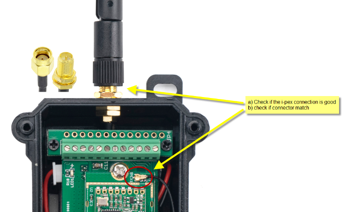
3.1 Check if the antenna path is good -- For LSN50v2 series end node
a) Open Enclosure and Check if the antenna connection to module is good.
b) check if the connector match.
4. Installation Guidelines
4.1 Check the use environment
First , User should notice: Radio link quality and performances are highly dependent of the environment.Even you have the same hardware and antenna, Different installation will result in different performance.
Better performances can be reached with:
- Outdoor environment.
- No obstacles.
- No high level radio interferes in the ISM band you use.
- At least 1 meter above the ground.
Radio performances are degraded with:
- Obstacles: buildings, trees...
- Inner buildings environments.
- High ISM band usage by other technologies.
- Radio communication are usually killed with bad topographic conditions. It is usually not possible to communicate through a hill, even very small.
4.2 Improve the Antenna
In some case, we have to install the device inside the chamber or next to a metal case. So the signal between the antenna and the receiver (gateway) is blocked by the metal. This will greatly reduce the signal. In such case, we can consider using antenna extend cable to extend the antenna to a better position.
5. Some real-world case
5.1 Server reason cause end node has problem on Join.
In one case, the customer is using AWS IoT Core and gateway to connect to AWS via Basic Station Connection, Frequency Band is AU915 sub-band 2. For some unknown reason, AWS always set downlink power to 0dBm, which cause the gateway only emit a very low power and lead to a short distance for sensor.
Below is the output log in gateway side ( SSH Access to Gateway and Check Station log)
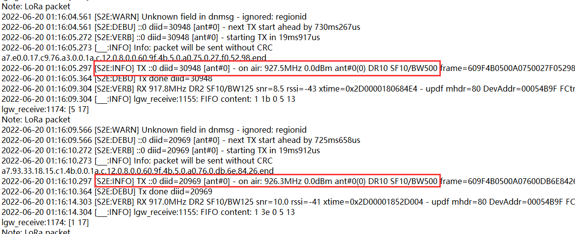
The fix of this issue is to set the output power to a high value even server ask to send out 0dBm.
Reference Link: http://wiki.dragino.com/xwiki/bin/view/Main/Change%20Gateway%20Power/#H1.A0Overview
5.2 Chirpstack Default settings to 64 channels which cause Signal Poor.
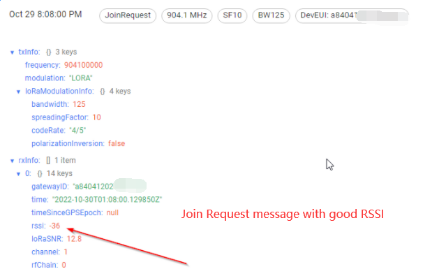
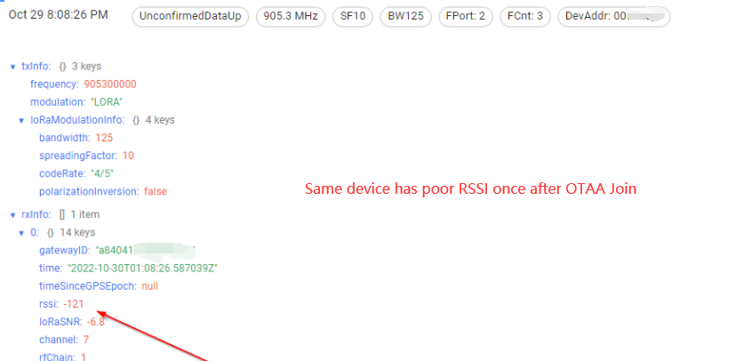
In this case, User use a Chirpstack LoRaWAN server with default settings. The Frequency Band is US915 and default settings of Chirpstack has all channels ( All sub-bands , total 72 channels) enable. User use a LDS03A and a LPS8N LoRaWAN gateway for the test.
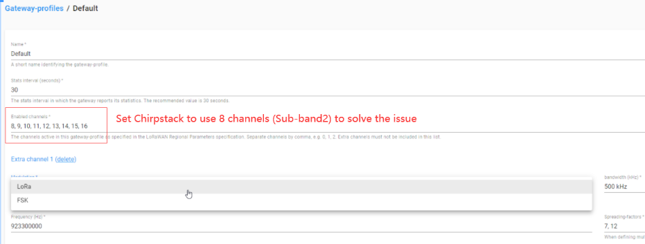
There is a strange issue: LDS03 has a very good RSSI ( RSSI=-40) during OTAA Join. But The LDS03A give a very poor RSSI after OTAA Join. After debug, it proves that the issue is with ChirpStack Frequency band settings. The ChirpStack server enables all 72 channels and the LDS03A will also use all channels after OTAA Join, but the LPS8N only can support 8 channels and set to Sub-Band2. When the LDS03A sends an uplink packet in the channel LPS8N doesn't support, because LDS03A is very close to LPS8N, LPS8N pick up this not support frequency and send to server. So in the platform we see a uplink packet with very poor RSSI.
Above issue was confirmed and solved after set the ChirpStack support channels to sub-band2. See below for photos during debug.
6. Use a repeater
In some cases, user can consider use a repeater for limitation transmition.
See here for how to set up: http://wiki.dragino.com/xwiki/bin/view/Main/User%20Manual%20for%20All%20Gateway%20models/LoRaWAN%20IoT%20Kit%20v3%20User%20Manual/#H7.Example6:LimitedLoRaWANrelay