General Configure/Commands to Connect to IoT server for -NB & -NS NB-IoT models
Table of Contents:
- 1. The use of this guideline
- 2. Attach Network
- 3. Configure to connect to different servers
1. The use of this guideline
This configure instruction is for Dragino NB-IoT models with -NB or -NS suffix, for example DDS75-NB. These models use the same NB-IoT Module BC660K-GL and has the same software structure. The have the same configure instruction to different IoT servers. Use can follow the instruction here to see how to configure to connect to those servers.
2. Attach Network
To attache NB-IoT sensors to NB-IoT Network, You need to:
- Get a NB-IoT SIM card from Service Provider. (Not the same as the SIM card we use in mobile phone)
- Insert the SIM card to Sensor
- Configure APN in the sensor (补充 APN 指令)

After doing above, the NB-IoT Sensors should be able to attach to NB-IoT network .
The -NB and -NS models support LTE Cat NB2, with below frequency band: multiple frequency bands of B1/B2/B3/B4/B5/B8/B12/B13/B14/B17/B18/B19/B20/B25/B28/B66/B70/B85 . Make sure you use a the NB-IoT SIM card.
| SIM Provider | APN | NB-IoT Coverage | Comments |
| 1NCE | iot.1nce.net | Austria, Belgium, Bulgaria, Croatia, Czech Republic, Denmark, Finland, Germany, Great Britain, Greece, Hungary, Ireland, Italy, Latvia, Malta, Netherlands, Norway, Puerto Rico, Russia, Slovak , Republic, Slovenia, Spain, Sweden, Switzerland, Taiwan, USA, US Virgin Islands | |
| China Mobile | No need configure | China Mainland, HongKong | |
| China Telecom | ctnb | China Mainland |
3. Configure to connect to different servers
3.1 General UDP Connection
The NB-IoT Sensor can send packet to server use UDP protocol.
3.1.1 Simulate UDP Connection by PC tool
We can use PC tool to simulate UDP connection to make sure server works ok.

3.1.2 Configure NB-IoT Sensor
3.1.2.1 AT Commands
AT Commands:
- AT+PRO=2,0 // Set to use UDP protocol to uplink ,Payload Type select Hex payload
- AT+SERVADDR=120.24.4.116,5601 // Set UDP server address and port
- AT+CFM=1 // If the server does not respond, this command is unnecessary
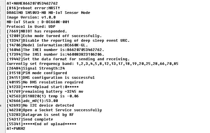
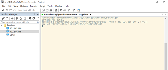
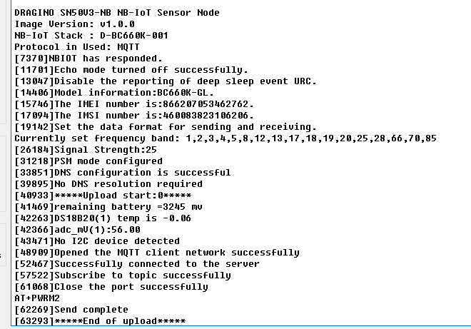
3.1.2.2 Uplink Example
3.2 General MQTT Connection
The NB-IoT Sensor can send packet to server use MQTT protocol.
Below are the commands.
AT Commands:
- AT+PRO=3,0 // Set to use MQTT protocol to uplink, Payload Type select Hex payload.
- AT+SERVADDR=120.24.4.116,1883 // Set MQTT server address and port
- AT+CLIENT=CLIENT // Set up the CLIENT of MQTT
- AT+UNAME=UNAME // Set the username of MQTT
- AT+PWD=PWD // Set the password of MQTT
- AT+PUBTOPIC=NSE01_PUB // Set the sending topic of MQTT
- AT+SUBTOPIC=NSE01_SUB // Set the subscription topic of MQTT

Notice: MQTT protocol has a much higher power consumption compare with UDP/CoAP protocol. Please check the power analyze document and adjust the uplink period to a suitable interval.
3.3 ThingSpeak (via MQTT)
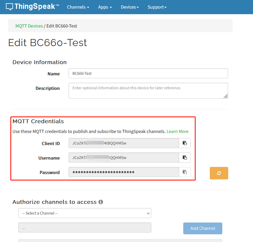
3.3.1 Get MQTT Credentials
ThingSpeak connection uses MQTT Connection. So we need to get MQTT Credentials first. You need to point MQTT Devices to ThingSpeak Channel as well.

3.3.2 Simulate with MQTT.fx
3.3.2.1 Establish MQTT Connection
After we got MQTT Credentials, we can first simulate with PC tool MQTT.fx tool to see if the Credentials and settings are fine.
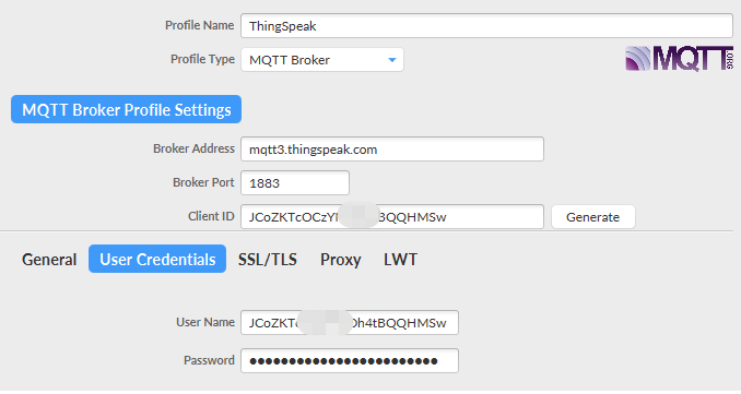
- Broker Address: mqtt3.thingspeak.com
- Broker Port: 1883
- Client ID: <Your ThingSpeak MQTT ClientID>
- User Name: <Your ThingSpeak MQTT User Name>
- Password: <Your ThingSpeak MQTT Password>
3.3.2.2 Publish Data to ThingSpeak Channel
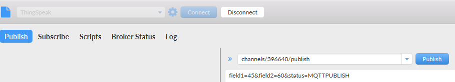
In MQTT.fx, we can publish below info:
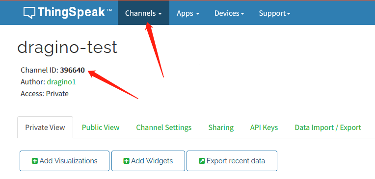
- Topic: channels/YOUR_CHANNEL_ID/publish
- Payload: field1=63&field2=67&status=MQTTPUBLISH
Where 63 and 67 are the value to be published to field1 & field2.
Result:

3.3.3 Configure NB-IoT Sensor for connection
3.3.3.1 AT Commands:
In the NB-IoT, we can run below commands so to publish the channels like MQTT.fx
- AT+PRO=3,1 // Set to use ThingSpeak Server and Related Payload
- AT+CLIENT=<Your ThingSpeak MQTT ClientID>
- AT+UNAME=<Your ThingSpeak MQTT User Name>
- AT+PWD=<Your ThingSpeak MQTT Password>
- AT+PUBTOPIC=<YOUR_CHANNEL_ID>
- AT+SUBTOPIC=<YOUR_CHANNEL_ID>
3.3.3.2 Uplink Examples
For S31-NB
For SE01-NB
For DDS20-NB
For DDS45-NB
For DDS75-NB
For NMDS120-NB
For SPH01-NB
For NLM01-NB
For NMDS200-NB
For CPN01-NB
For DS03A-NB
For SN50V3-NB
3.3.3.3 Map fields to sensor value
When NB-IoT sensor upload to ThingSpeak. The payload already specify which fileds related to which sensor value. Use need to create fileds in Channels Settings. with name so to see the value correctly.


Below is the NB-IoT Product Table show the mapping.
| Field1 | Field2 | Field3 | Field4 | Field5 | Field6 | Field7 | Field8 | Field9 | Field10 | |
| S31x-NB | Temperature | Humidity | Battery | RSSI | ||||||
| SE01-NB | Temperature | Humidity | conduct | dielectric_constant | Battery | RSSI | ||||
| DDS20-NB | distance | Battery | RSSI | |||||||
| DDS45-NB | distance | Battery | RSSI | |||||||
| DDS75-NB | distance | Battery | RSSI | |||||||
| NMDS120-NB | distance | Battery | RSSI | |||||||
| SPH01-NB | ph | Temperature | Battery | RSSI | ||||||
| NLM01-NB | Humidity | Temperature | Battery | RSSI | ||||||
| NMDS200-NB | distance1 | distance2 | Battery | RSSI | ||||||
| CPN01-NB | alarm | count | door open duration | calc flag | Battery | RSSI | ||||
| DS03A-NB | level | alarm | pb14door open num | pb14 last open time | pb15 level status | pb15 alarm status | pb15 door open num | pb15 last open time | Battery | RSSI |
| SN50V3-NB mod1 | mod | Battery | RSSI | DS18B20 Temp | exit_state/input PA4 | adc0 | Temperature | Humidity | ||
| SN50V3-NB mod2 | mod | Battery | RSSI | DS18B20 Temp | exit_state/input PA4 | adc0 | distance | |||
| SN50V3-NB mod3 | mod | Battery | RSSI | adc0 | exit_state/input PA4 | adc1 | Temperature | Humidity | adc4 | |
| SN50V3-NB mod4 | mod | Battery | RSSI | DS18B20 Temp | adc0 | exit_state/input PA4 | DS18B20 Temp2 | DS18B20 Temp3 | ||
| SN50V3-NB mod5 | mod | Battery | RSSI | DS18B20 Temp | adc0 | exit_state/input PA4 | Weight | |||
| SN50V3-NB mod6 | mod | Battery | RSSI | count |
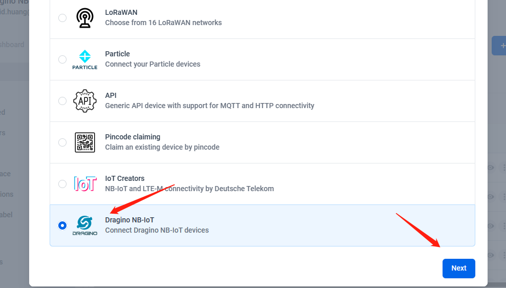
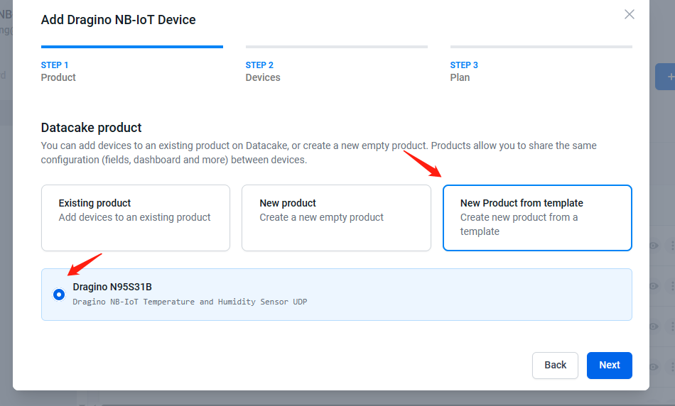
3.4 Datacake
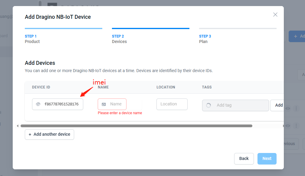
3.4.1 Create device
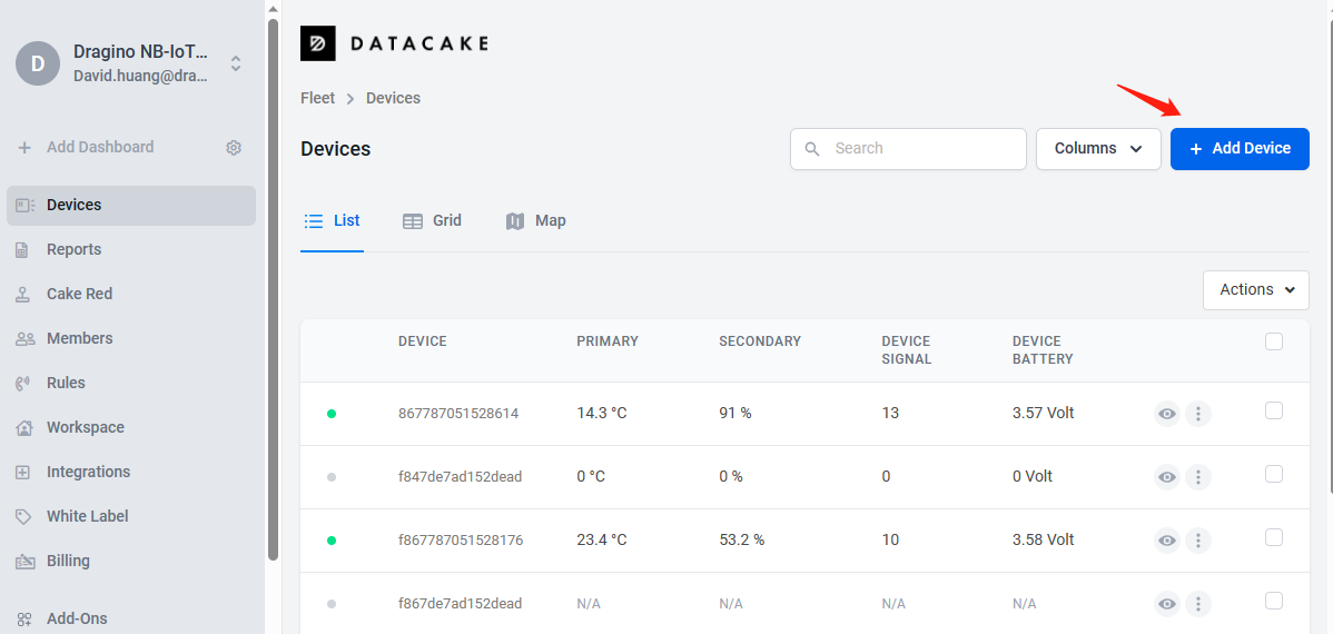
The device ID needs to be filled in with IMEI, and a prefix of 'f' needs to be added.
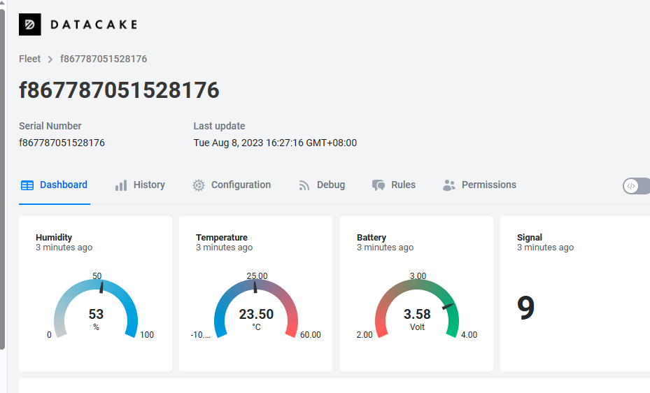
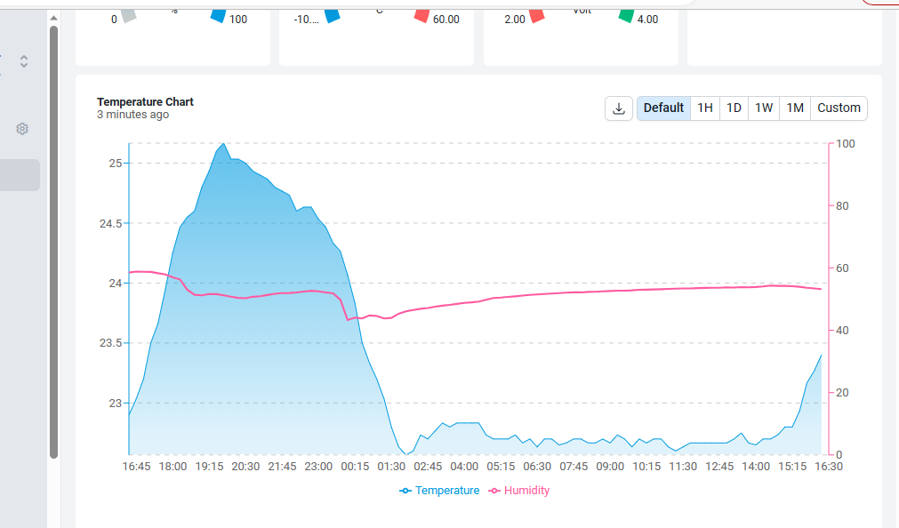
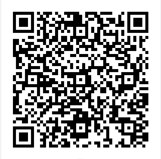
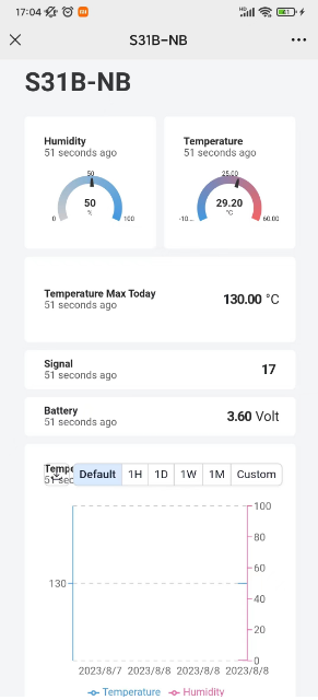
3.4.2 Scan QR code to obtain data
Users can use their phones or computers to scan QR codes to obtain device data information.
3.4.2 AT command for connecting to DataCake
AT+PRO=2,0
AT+SERVADDR=67.207.76.90,4445
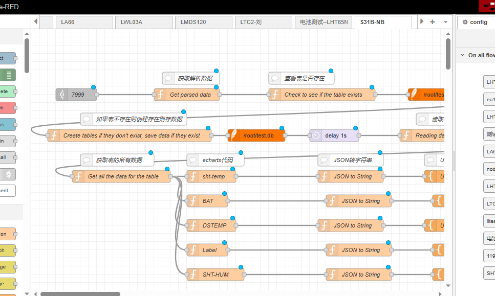
3.5 Node-Red (via MQTT)
3.5.1 Configure Node-Red
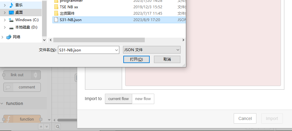
Take S31-NB UDP protocol as an example.
Dragino provides input flow examples for the sensors.
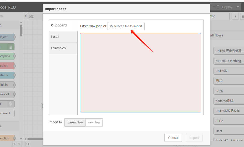
User can download the required JSON file through Dragino Node-RED input flow template.
Download sample JSON file link: https://www.dropbox.com/sh/mduw85jcuwsua22/AAAvwPhg9z6dLjJhmZjqBf_ma?dl=0
We can directly import the template.
The templates for S31-NB and NB95S31B are the same.
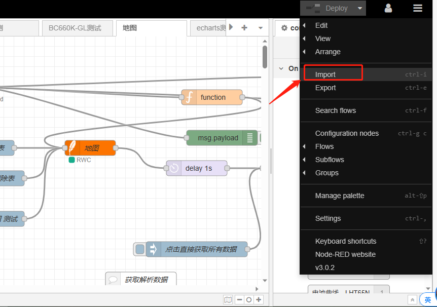
Please select the NB95S31B template.
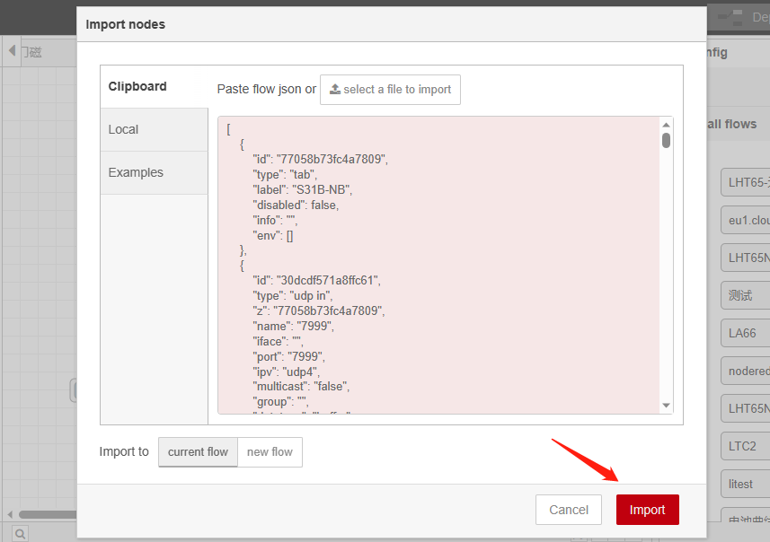
Successfully imported template.
Users can set UDP port.
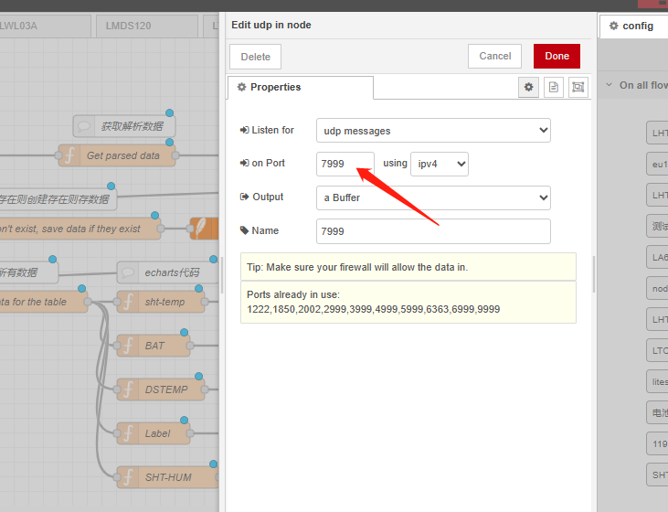
3.5.2 Simulate Connection
We have completed the configuration of UDP. We can try sending packets to node red.
3.5.3 Configure NB-IoT Sensors
- AT+PRO=2,0(hex format) or 2,1(json format) // Set to UDP Server and Payload
- AT+SERVADDR=xx.xx.xx.xx,port // Set Server IP and port
3.6 ThingsBoard.Cloud (via MQTT)
3.6.1 Configure ThingsBoard
3.6.1.1 Create Device
Create a New Device in ThingsBoard. Record Device Name which is used for MQTT connection.

3.6.1.2 Create Uplink & Downlink Converter
Uplink Converter
The purpose of the decoder function is to parse the incoming data and metadata to a format that ThingsBoard can consume. deviceName and deviceType are required, while attributes and telemetry are optional. Attributes and telemetry are flat key-value objects. Nested objects are not supported.
To create an uplink converter go to the Integrations center -> Data converters page and click “plus” button. Name it “MQTT Uplink Converter” and select type "Uplink". Use debug mode for now.

Downlink Converter
The Downlink converter transforming outgoing RPC message and then the Integration sends it to external MQTT broke

Note: Our device payload is already human readable data. Therefore, users do not need to write decoders. Simply create by default.
3.6.1.3 MQTT Integration Setup
Go to the Integrations center -> Integrations page and click “plus” icon to add a new integration. Name it “MQTT Integration”, select type MQTT;

- The next steps is to add the recently created uplink and downlink converters;


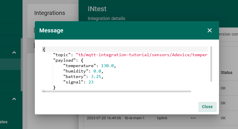
Add a topic filter:
tb/mqtt-integration-tutorial/sensors//temperature --> Temperature 固定的? 对的。
You can also select an MQTT QoS level. We use MQTT QoS level 0 (At most once) by default;

3.6.2 Simulate with MQTT.fx

3.6.3 Configure NB-IoT Sensor
AT Commands
- AT+PRO=3,3 // Use MQTT to connect to ThingsBoard. Payload Type set to 3.
- AT+SUBTOPIC=<device name>
- AT+PUBTOPIC=<device name>
- AT+CLIENT=<device name> or User Defined
- AT+UNAME=<device name> or User Defined
- AT+PWD=<device name> or User Defined
Test Uplink by click the button for 1 second


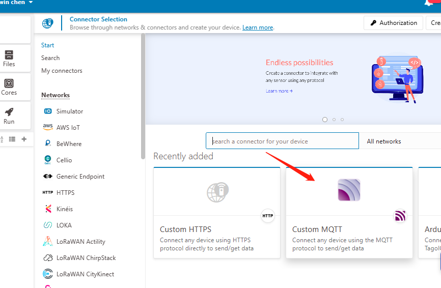
3.7 Tago.io (via MQTT)
3.7.1 Create device & Get Credentials
We use MQTT Connection to send data to Tago.io. We need to Create Device and Get MQTT Credentials first.
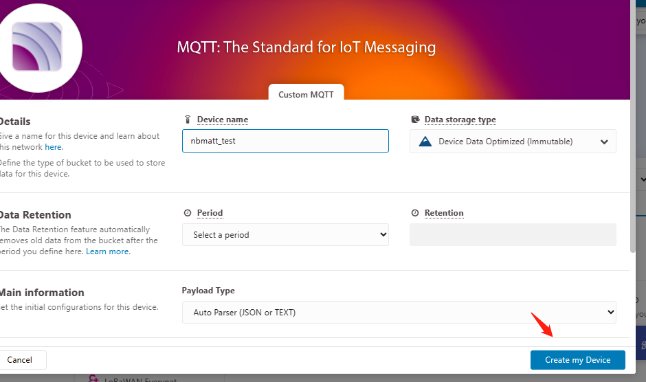
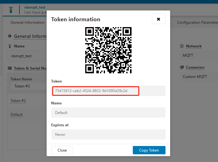
Go to the Device section and create a device. Then, go to the section tokens and copy your device-token.
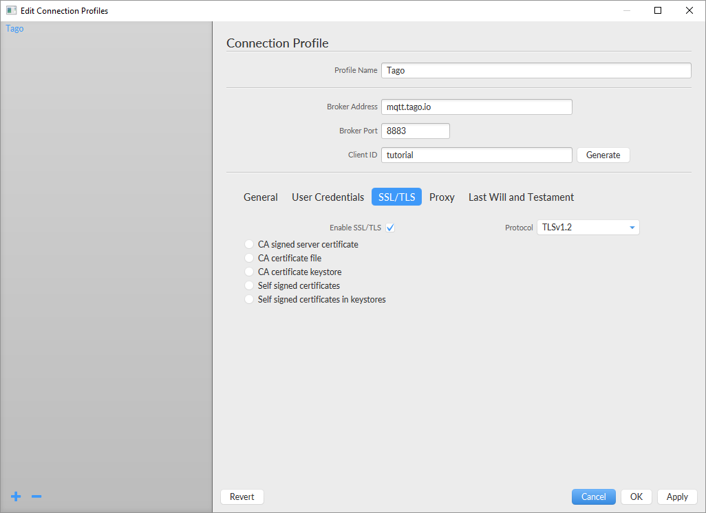
The device needs to enable the TLS mode and set the AT+TLSMOD=1,0 command.
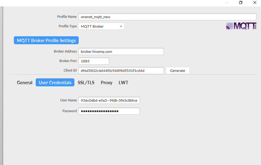
On the Connection Profile window, set the following information:
- Profile Name: “Any name”
- Broker Address: mqtt.tago.io
- Broker Port: 8883
- Client ID: “Any value”
On the section User credentials, set the following information:
- User Name: “Any value” // Tago validates your user by the token only
- Password: “Your device token”
- PUBTOPIC: “Any value”
- SUBTOPIC: “Any value”
AT command:
- AT+PRO=3,0 or 3,5 // hex format or json format
- AT+SUBTOPIC=<device name>or User Defined
- AT+PUBTOPIC=<device name>or User Defined
- AT+CLIENT=<device name> or User Defined
- AT+UNAME=<device name> or User Defined
- AT+PWD=“Your device token”
3.7.2 Simulate with MQTT.fx

Users can run the AT+PRO=3,5 command, and the payload will be converted to JSON format.

3.7.3 tago data


3.8 TCP Connection
AT command:
- AT+PRO=4,0 // Set to use TCP protocol to uplink(HEX format)
- AT+PRO=4,1 // Set to use TCP protocol to uplink(JSON format)
- AT+SERVADDR=120.24.4.116,5600 // to set TCP server address and port
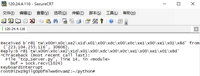
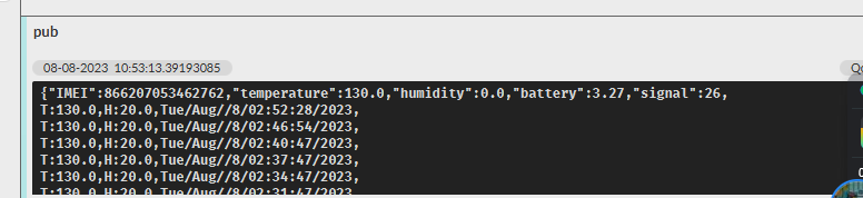
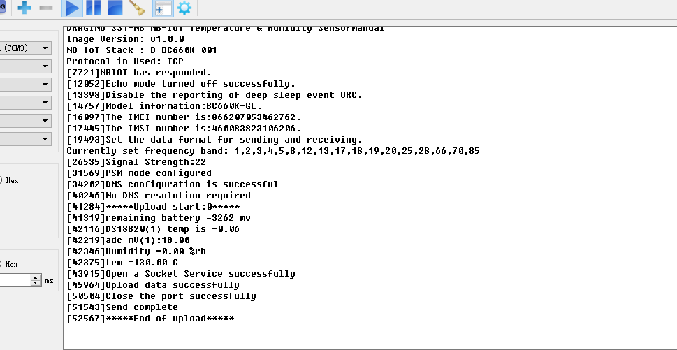
Sensor Console Output when Uplink:
See result in TCP Server: