1. Overview
Shipped LT-22222-L is base on LoRaWAN protocol. We also develop a open source Point to Point LoRa protocol for LT-22222-L. The source code and hex file can be found at:
2. Features for this firmware
2.1 Point To Point
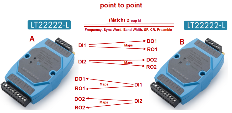
Configure:
| A's configuration | B's configuration |
|---|---|
| AT+GROUPMOD=0 | AT+GROUPMOD=0 |
| AT+TXCHS=868700000 | AT+TXCHS=869000000 |
| AT+RXCHS=869000000 | AT+RXCHS=868700000 |
| AT+TRIG1=2,50 | AT+TRIG1=2,50 |
| AT+TRIG2=2,50 | AT+TRIG2=2,50 |
| AT+DI1TODO1=2 | AT+DI1TODO1=2 |
| AT+DI1TORO1=2 | AT+DI1TORO1=2 |
| AT+DI2TODO2=2 | AT+DI2TODO2=2 |
| AT+DI2TORO2=2 | AT+DI2TORO2=2 |
2.2 Point To Mult-Point
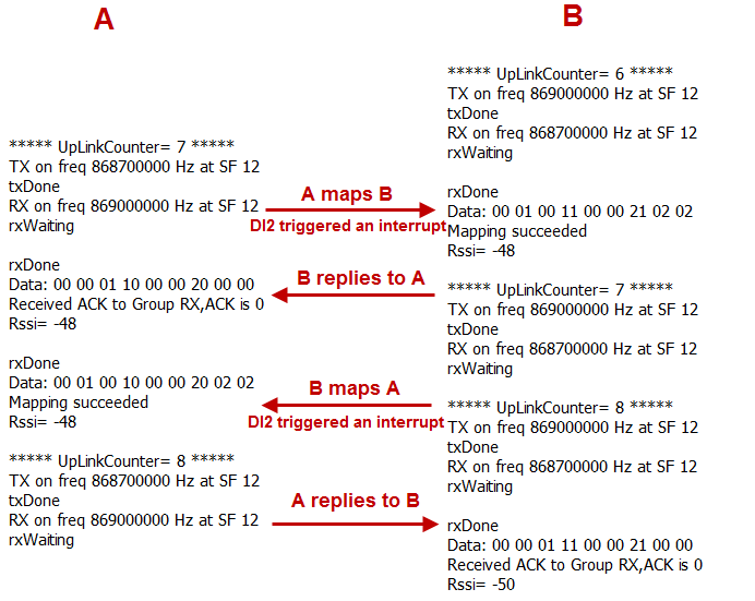
If the sender does not get the ACK reply from the receiver, it will retransmit up to 4 times, each interval is 6 seconds, and the UplinkCounter of the retransmission will not increase.
2.3 AT command
ATZ : Trig a reset of the MCU
AT+FDR : Reset Parameters to Factory Default, Keys Reserve
AT+FCU : Get or Set the Frame Counter Uplink
AT+FCD : Get or Set the Frame Counter Downlink
AT+TXP : Get or Set the transmit power, the maximum is 20dBm (default is 14dBm)
AT+SYNC : Get or Set the Sync word [1:0x34,0:0x12] (default is 1)
AT+PMB : Get or Set the preamble (default:8)
AT+TXCHS : Get or Set the transmit frequency of TX (default:868700000)
AT+TXSF : Get or Set the spreading factor of TX (7 to 12) (default:12)
AT+RXCHS : Get or Set the transmit frequency of RX (default:869000000)
AT+RXSF : Get or Set the spreading factor of RX (7 to 12) (default:12)
AT+BW : Get or Set the bandwidth [0:125khz,1:250khz,2:500khz] (default:0)
AT+CR : Get or Set the coding rate [1: 4/5, 2: 4/6, 3: 4/7, 4: 4/8] (default:1)
AT+TDC : Get or set the application data transmission interval in ms(default 10 minutes)
AT+VER : Get firmware version number
AT+SEND : Set Custom sent hex data
AT+GROUPMOD : Set or Get the grouping mode of the device (default: 0)
AT+GROUPID : Set or Get the password for matching between TX group and RX group, which can be composed of numbers or characters (default: 12345678)
AT+TRIG1 : Set or Get the DI1 pin interrupt trigger mode (default 0,0)
AT+TRIG2 : Set or Get the DI2 pin interrupt trigger mode (default 0,0)
AT+DI1TODO1 : Set or get the mode in which DI1 maps to DO1 (default 0)
AT+DI1TORO1 : Set or get the mode in which DI1 maps to RO1(default 0)
AT+DI2TODO2 : Set or get the mode in which DI2 maps to DO2(default 0)
AT+DI2TORO2 : Set or get the mode in which DI2 maps to RO2(default 0)
Example 1:
AT+SEND=01020304 will send a payload of 01020304
Example 2:
AT+TRIGx=a Trigger directly without triggering time
AT+TRIGx=a,b
a=0: falling edge;
a=1: rising edge;
a=2: falling edge or rising edge;
b: triggering time in milliseconds.
AT+TRIGx=2,50 Falling edge or rising edge trigger, and the trigger time exceeds 50ms.
Example 3:
AT+DI1TODO1= maps value
AT+DI1TORO1= maps value
AT+DI2TODO2= maps value
AT+DI2TORO2= maps value
Maps value | DIx to DOx | DIx to ROx |
|---|---|---|
0 | No Action | No Action |
1 | If DIx is high, control DOx to output low level, If DIx is low, control DOx to output high level | If DIx is high, control ROx to close, if DIx is low, control ROx to open |
2 | If DIx is high, control DOx to output high level, If DIx is low, control DOx to output low level | If DIx is high, control ROx to open, if DIx is low, control ROx to close |
3 | DOx state flip | ROx state flip |
Example 4:
AT+GROUPMOD=0 Set to point to point mode
AT+GROUPMOD=0,aa Set the TX group that controls the number of aa (The maximum value of aa is 8)
AT+GROUPMOD=1,bb Set to the RX group controlled by the TX group, numbered bb(The maximum value of aa is 8)
AT+GROUPMOD=0,2 Set to control the TX group of the two RX groups
AT+GROUPMOD=1,1 Set the RX group numbered 1
AT+GROUPMOD=1,2 Set the RX group numbered 2
2.4 Data Format
8 bytes of GROUPID + 9 bytes of payload + 4 bytes of checksum
Payload:
Size (bytes) | 1 | 1 | 1 | 1 | 1 | 1 | 1 | 1 | 1 |
|---|---|---|---|---|---|---|---|---|---|
Value | address | request | ACK | DI1& DI1 level | DI1TODO1 | DI1TORO1 | DI2& DI2 level | DI2TODO2 | DI2TORO2 |
The first byte: 00 is the broadcast address, 01-08 is the RX group number.
The second byte: send mapping request when not 0, not request when it is 0.
The third byte: ACK returned to the sender after the mapping is completed.
The fourth byte: the high four bits are 1 to represent DI1, and the low four bits are the level of DI1 when the interrupt is triggered.
The Fifth byte: DI1TODO1 when the interrupt is triggered, 0 when the interrupt is not triggered.
The Sixth byte: 0 does not trigger interrupt when DI1TORO1 interrupt is triggered.
The seventh byte: the high four bits are 2 to represent DI2, and the low four bits are the level of DI2 when the interrupt is triggered.
The 8th byte: DI2TODO2 when the interrupt is triggered, 0 when the interrupt is not triggered.
The 9th byte: DI2TORO2 when an interrupt is triggered, 0 when an interrupt is not triggered.