RS485-LN – RS485 to LoRaWAN Converter User Manual
Table of Contents:
1.Introduction
1.1 What is RS485-LN RS485 to LoRaWAN Converter
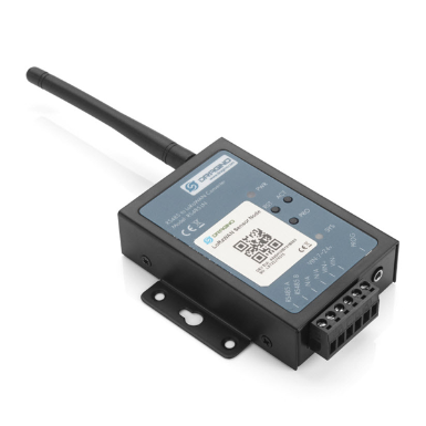
The Dragino RS485-LN is a RS485 to LoRaWAN Converter. It converts the RS485 signal into LoRaWAN wireless signal which simplify the IoT installation and reduce the installation/maintaining cost.
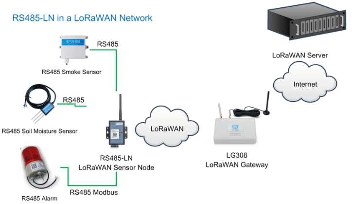
RS485-LN allows user to monitor / control RS485 devices and reach extremely long ranges. It provides ultra-long range spread spectrum communication and high interference immunity whilst minimizing current consumption. It targets professional wireless sensor network applications such as irrigation systems, smart metering, smart cities, smartphone detection, building automation, and so on.
For data uplink, RS485-LN sends user-defined commands to RS485 devices and gets the return from the RS485 devices. RS485-LN will process these returns according to user-define rules to get the final payload and upload to LoRaWAN server.
For data downlink, RS485-LN runs in LoRaWAN Class C. When there downlink commands from LoRaWAN server, RS485-LN will forward the commands from LoRaWAN server to RS485 devices.
Demo Dashboard for RS485-LN connect to two energy meters: https://app.datacake.de/dashboard/d/58844a26-378d-4c5a-aaf5-b5b5b153447a
1.2 Specifications
Hardware System:
- STM32L072CZT6 MCU
- SX1276/78 Wireless Chip
- Power Consumption (exclude RS485 device):
- Idle: 32mA@12v
- 20dB Transmit: 65mA@12v
Interface for Model:
- RS485
- Power Input 7~ 24V DC.
LoRa Spec:
- Frequency Range:
- Band 1 (HF): 862 ~ 1020 Mhz
- Band 2 (LF): 410 ~ 528 Mhz
- 168 dB maximum link budget.
- +20 dBm - 100 mW constant RF output vs.
- +14 dBm high efficiency PA.
- Programmable bit rate up to 300 kbps.
- High sensitivity: down to -148 dBm.
- Bullet-proof front end: IIP3 = -12.5 dBm.
- Excellent blocking immunity.
- Low RX current of 10.3 mA, 200 nA register retention.
- Fully integrated synthesizer with a resolution of 61 Hz.
- FSK, GFSK, MSK, GMSK, LoRaTM and OOK modulation.
- Built-in bit synchronizer for clock recovery.
- Preamble detection.
- 127 dB Dynamic Range RSSI.
- Automatic RF Sense and CAD with ultra-fast AFC.
- Packet engine up to 256 bytes with CRC.
1.3 Features
- LoRaWAN Class A & Class C protocol (default Class C)
- Frequency Bands: CN470/EU433/KR920/US915/EU868/AS923/AU915/IN865/RU864
- AT Commands to change parameters
- Remote configure parameters via LoRa Downlink
- Firmware upgradable via program port
- Support multiply RS485 devices by flexible rules
- Support Modbus protocol
- Support Interrupt uplink (Since hardware version v1.2)
1.4 Applications
- Smart Buildings & Home Automation
- Logistics and Supply Chain Management
- Smart Metering
- Smart Agriculture
- Smart Cities
- Smart Factory
1.5 Firmware Change log
RS485-LN Image files – Download link and Change log
1.6 Hardware Change log
v1.2: Add External Interrupt Pin.
v1.0: Release
2. Power ON Device
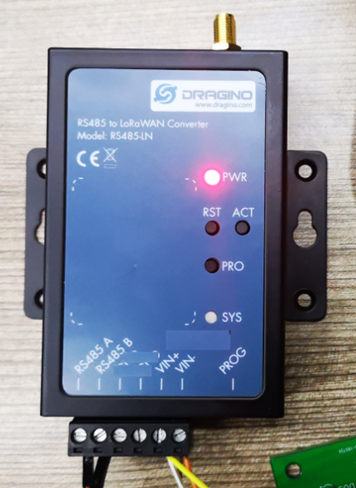
The RS485-LN can be powered by 7 ~ 24V DC power source. Connection as below
- Power Source VIN to RS485-LN VIN+
- Power Source GND to RS485-LN VIN-
Once there is power, the RS485-LN will be on.
3. Operation Mode
3.1 How it works?
The RS485-LN is configured as LoRaWAN OTAA Class C mode by default. It has OTAA keys to join network. To connect a local LoRaWAN network, user just need to input the OTAA keys in the network server and power on the RS485-LN. It will auto join the network via OTAA.
3.2 Example to join LoRaWAN network
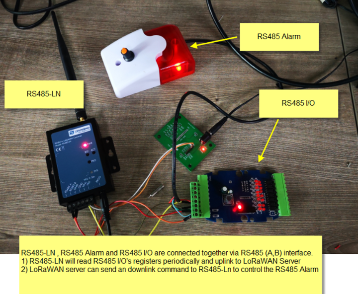
Here shows an example for how to join the TTN V3 Network. Below is the network structure, we use LG308 as LoRaWAN gateway here.
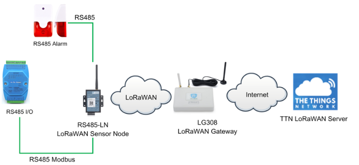
The RS485-LN in this example connected to two RS485 devices for demonstration, user can connect to other RS485 devices via the same method. The connection is as below:
485A+ and 485B- of the sensor are connected to RS485A and RA485B of RS485-LN respectively.
The LG308 is already set to connect to TTN V3 network . So what we need to now is only configure the TTN V3:
Step 1: Create a device in TTN V3 with the OTAA keys from RS485-LN.
Each RS485-LN is shipped with a sticker with unique device EUI:
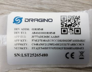
User can enter this key in their LoRaWAN Server portal. Below is TTN V3 screen shot:
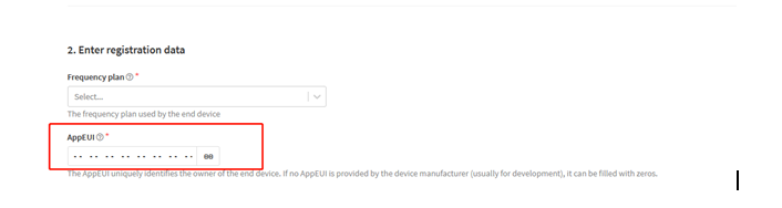
Add APP EUI in the application.
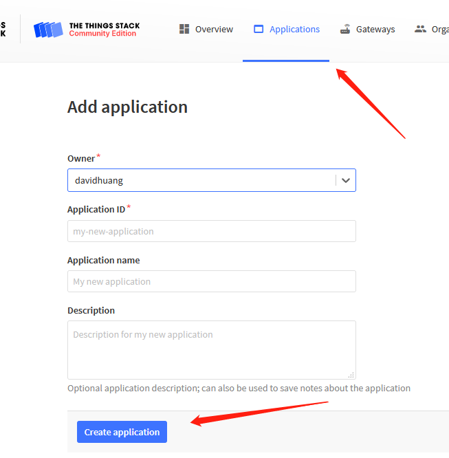
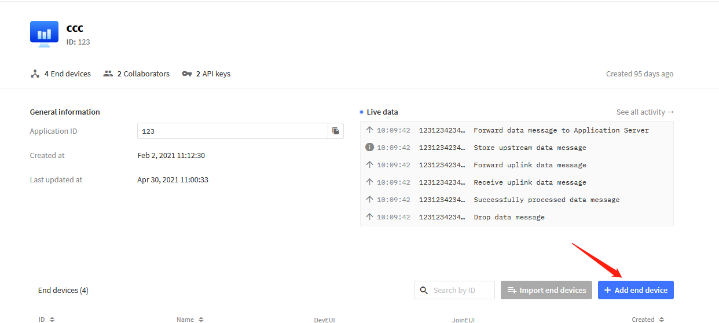
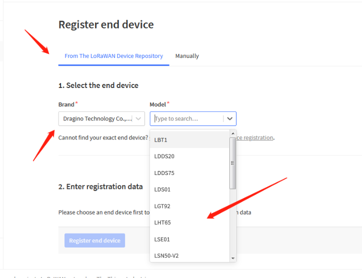
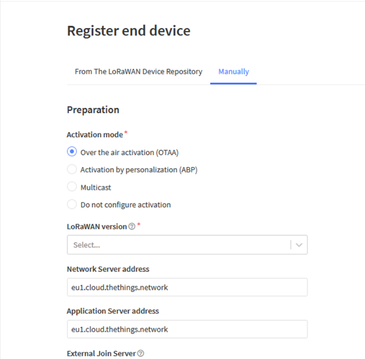
You can also choose to create the device manually.
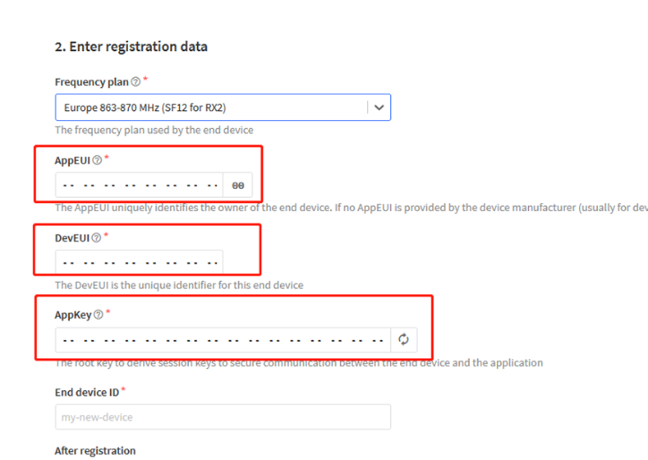
Add APP KEY and DEV EUI
Step 2: Power on RS485-LN and it will auto join to the TTN V3 network. After join success, it will start to upload message to TTN V3 and user can see in the panel.
3.3 Configure Commands to read data
There are plenty of RS485 devices in the market and each device has different command to read the valid data. To support these devices in flexible, RS485-LN supports flexible command set. User can use AT Commands or LoRaWAN Downlink Command to configure what commands RS485-LN should send for each sampling and how to handle the return from RS485 devices.
Note: below description and commands are for firmware version >v1.1, if you have firmware version v1.0. Please check the user manual v1.0 or upgrade the firmware to v1.1
3.3.1 onfigure UART settings for RS485 or TTL communication
To use RS485-LN to read data from RS485 sensors, connect the RS485-LN A/B traces to the sensors. And user need to make sure RS485-LN use the match UART setting to access the sensors. The related commands for UART settings are:
AT Commands | Description | Example |
AT+BAUDR | Set the baud rate (for RS485 connection). Default Value is: 9600. | AT+BAUDR=9600 Options: (1200,2400,4800,14400,19200,115200) |
AT+PARITY | Set UART parity (for RS485 connection) | AT+PARITY=0 Option: 0: no parity, 1: odd parity, 2: even parity |
AT+STOPBIT | Set serial stopbit (for RS485 connection)
| AT+STOPBIT=0 for 1bit AT+STOPBIT=1 for 1.5 bit AT+STOPBIT=2 for 2 bits |
3.3.2 Configure sensors
Some sensors might need to configure before normal operation. User can configure such sensor via PC and RS485 adapter or through RS485-LN AT Commands AT+CFGDEV. Each AT+CFGDEV equals to send a RS485 command to sensors. This command will only run when user input it and won’t run during each sampling.
| AT Commands | Description | Example |
| AT+CFGDEV | This command is used to configure the RS485/TTL devices; they won’t be used during sampling. AT+CFGDEV=xx xx xx xx xx xx xx xx xx xx xx xx, mm: 0: no CRC, 1: add CRC-16/MODBUS in the end of this command | AT+CFGDEV=xx xx xx xx xx xx xx xx xx xx xx xx,m |
3.3.3 Configure read commands for each sampling
During each sampling, we need confirm what commands we need to send to the RS485 sensors to read data. After the RS485 sensors send back the value, it normally include some bytes and we only need a few from them for a shorten payload.
To save the LoRaWAN network bandwidth, we might need to read data from different sensors and combine their valid value into a short payload.
This section describes how to achieve above goals.
During each sampling, the RS485-LN can support 15 commands to read sensors. And combine the return to one or several uplink payloads.
Each RS485 commands include two parts:
1. What commands RS485-LN will send to the RS485 sensors. There are total 15 commands from AT+COMMAD1, ATCOMMAND2,…, to AT+COMMANDF. All commands are of same grammar.
2. How to get wanted value the from RS485 sensors returns from by 1). There are total 15 AT Commands to handle the return, commands are AT+DATACUT1,AT+DATACUT2,…, AT+DATACUTF corresponding to the commands from 1). All commands are of same grammar.
3. Some RS485 device might has longer delay on reply, so user can use AT+CMDDL to set the timeout for getting reply after the RS485 command is sent. For example AT+CMDDL1=1000 to send the open time to 1000ms
After we got the valid value from each RS485 commands, we need to combine them together with the command AT+DATAUP.
Below are examples for the how above AT Commands works.
AT+COMMANDx : This command will be sent to RS485 devices during each sampling, Max command length is 14 bytes. The grammar is:
AT+COMMANDx=xx xx xx xx xx xx xx xx xx xx xx xx,m xx xx xx xx xx xx xx xx xx xx xx xx: The RS485 command to be sent m: 0: no CRC, 1: add CRC-16/MODBUS in the end of this command |
For example, if we have a RS485 sensor. The command to get sensor value is: 01 03 0B B8 00 02 46 0A. Where 01 03 0B B8 00 02 is the Modbus command to read the register 0B B8 where stored the sensor value. The 46 0A is the CRC-16/MODBUS which calculate manually.
In the RS485-LN, we should use this command AT+COMMAND1=01 03 0B B8 00 02,1 for the same.
AT+DATACUTx : This command defines how to handle the return from AT+COMMANDx, max return length is 45 bytes.
AT+DATACUTx=a,b,c
|
Examples:
- Grab bytes:

- Grab a section.

- Grab different sections.

3.3.4 Compose the uplink payload
Through AT+COMMANDx and AT+DATACUTx we got valid value from each RS485 commands, Assume these valid value are RETURN1, RETURN2, .., to RETURNx. The next step is how to compose the LoRa Uplink Payload by these RETURNs. The command is AT+DATAUP.
Examples: AT+DATAUP=0
Compose the uplink payload with value returns in sequence and send with A SIGNLE UPLINK.
Final Payload is
Battery Info+PAYVER + VALID Value from RETURN1 + Valid Value from RETURN2 + … + RETURNx
Where PAYVER is defined by AT+PAYVER, below is an example screen shot.

Examples: AT+DATAUP=1
Compose the uplink payload with value returns in sequence and send with Multiply UPLINKs.
Final Payload is
Battery Info+PAYVER + PAYLOAD COUNT + PAYLOAD# + DATA
- PAYVER: Defined by AT+PAYVER
- PAYLOAD COUNT: Total how many uplinks of this sampling.
- PAYLOAD#: Number of this uplink. (from 0,1,2,3…,to PAYLOAD COUNT)
- DATA: Valid value: max 8 bytes for each uplink so each uplink <= 11 bytes. For the last uplink, DATA will might less than 8 bytes

So totally there will be 3 uplinks for this sampling, each uplink include 8 bytes DATA
DATA1=RETURN1 Valid Value + the first two of Valid value of RETURN10= 20 20 0a 33 90 41 02 aa
DATA2=3rd ~ 10th byte of Valid value of RETURN10= 05 81 0a 20 20 20 20 2d
DATA3=the rest of Valid value of RETURN10= 30
Notice: In firmware v1.3, the Max bytes has been changed according to the max bytes in different Frequency Bands for lowest SF. As below:
* For AU915/AS923 bands, if UplinkDwell time=0, max 51 bytes for each uplink.
* For AU915/AS923 bands, if UplinkDwell time=0, max 11 bytes for each uplink.
* For US915 band, max 11 bytes for each uplink.
* For all other bands: max 51 bytes for each uplink.
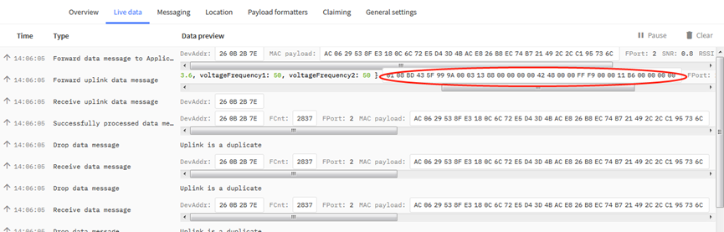
Below are the uplink payloads:

3.3.5 Uplink on demand
Except uplink periodically, RS485-LN is able to uplink on demand. The server send downlink command to RS485-LN and RS485 will uplink data base on the command.
Downlink control command:
0x08 command: Poll an uplink with current command set in RS485-LN.
0xA8 command: Send a command to RS485-LN and uplink the output from sensors.
3.3.6 Uplink on Interrupt
RS485-LN support external Interrupt uplink since hardware v1.2 release.

Connect the Interrupt pin to RS485-LN INT port and connect the GND pin to V- port. When there is a high voltage (Max 24v) on INT pin. Device will send an uplink packet.
3.4 Uplink Payload
| Size(bytes) | 2 | 1 | Length depends on the return from the commands |
| Value | Battery(mV) & Interrupt _Flag | PAYLOAD_VER
| If the valid payload is too long and exceed the maximum support payload length in server, server will show payload not provided in the LoRaWAN server. |
Below is the decoder for the first 3 bytes. The rest bytes are dynamic depends on different RS485 sensors.
3.5 Configure RS485-BL via AT or Downlink
User can configure RS485-LN via AT Commands or LoRaWAN Downlink Commands
There are two kinds of Commands:
- Common Commands: They should be available for each sensor, such as: change uplink interval, reset device. For firmware v1.3, user can find what common commands it supports: End Device AT Commands and Downlink Command
- Sensor Related Commands: These commands are special designed for RS485-LN. User can see these commands below:
3.5.1 Common Commands
They should be available for each of Dragino Sensors, such as: change uplink interval, reset device. For firmware v1.3, user can find what common commands it supports: End Device AT Commands and Downlink Command
3.5.2 Sensor related commands
Response feature is added to the server's downlink, a special package with a FPort of 200 will be uploaded immediately after receiving the data sent by the server.

The first byte of this package represents whether the configuration is successful, 00 represents failure, 01 represents success. Except for the first byte, the other is the previous downlink. (All commands except A8 type commands are applicable)
3.5.3 Sensor related commands