
Table of Contents:
- 1. Introduction
- 2. Power ON LWL02
- 3. How to install LWL02
- 4. Operation Mode
- 5. Battery
- 6. Use AT Commands
- 7. FAQ
- 7.1 How to upgrade the image?
- 7.2 How to change the LoRa Frequency Bands/Region?
- 7.3 Can I disable uplinks for each event to save battery life?
- 7.4 How can I change the Subband for LWL02?
- 7.5 My sensor worked for Helium AU915 before, but now it doesn't work. Why?
- 7.6 Why do I see different working temperatures for the device?
- 8. Ordering Information
- 9. Packaging Information
- 10. Support
1. Introduction
1.1 What is the LWL02 LoRaWAN Water Leak Sensor
The Dragino LWL02 is a LoRaWAN Water Leak Sensor equipped with two external metal probes. When water is detected between the two metal probes, the LWL02 identifies a water leak and sends an uplink to the registered LoRaWAN network server.
The LWL02 is powered by 2 x AAA batteries and is designed for long-term use. These two batteries can support approximately 16,000 to 70,000 uplink packets, resulting in a battery life of 2 to 10 years. Once the batteries are depleted, users can easily open the enclosure and replace them with standard AAA batteries.
The LWL02 sends data periodically every day and also for each water leak event. It records the number of water leak occurrences and calculates the duration of the most recent leak. Users can disable uplinks for each individual water leak event if desired. In this case, the device will count each event and send the data periodically.
Each LWL02 comes preloaded with a unique set of key/EUIs for LoRaWAN registration. By registering these keys to the LoRaWAN network server, the device will automatically connect upon powering on.

1.2 Features
- LoRaWAN Class A v1.0.3
- Frequency Bands: CN470, EU433, KR920, US915, EU868, AS923, AU915, IN865, RU864
- SX1262 LoRa Core
- Water Leak Detection
- 2 x AAA LR03 Batteries
- AT Commands to change parameters
- Periodic Uplink and uplink triggered by open/close actions
- Remote Configuration of parameters via LoRa Downlink
- Firmware Upgradable via programming port
1.3 Storage & Operation Temperature
-10 ~ 50 °C or -40 ~ 60 °C (depending on the battery type; see FAQ)
1.4 Applications
- Smart Buildings & Home Automation
- Logistics and Supply Chain Management
- Smart Metering
- Smart Agriculture
- Smart Cities
- Smart Factory
1.5 Dimensions


1.6 Firmware Change log
The LWL02 uses the same firmware as the LDS01: https://www.dropbox.com/sh/6ls5i0zsvujvbc8/AABe3V5aQXdy7zSxEdEA3DHOa?dl=0
2. Power ON LWL02
When you receive the LWL02, open the enclosure and insert 2 AAA batteries to power it on. The LED will blink when the device is powered.
3. How to install LWL02
Fixing with screws:
- Detach the bottom lid of the enclosure. You will notice two holes on the bottom lid for inserting screws. First, attach the bottom lid to the surface using screws. Then snap the top part of the enclosure onto the bottom. You will hear a clicking sound once they are securely fitted together.

Fixing with double-sided adhesive pads:
- A double-sided adhesive pad is included with the LWL02. First remove the protective backing of one side only. Then affix it on the bottom of the sensor enclosure. Once the tape is in place, remove the remaining protective backing and secure the enclosure to the surface.

When installing the LWL02 on a wall, please follow the instructions as shown in the image below to ensure the water leak probe is submerged in water for detection purposes. The LWL02 main body is not waterproof, so please avoid allowing water to enter the main body.

4. Operation Mode
4.1 How It works?
The LDS02 is configured as a LoRaWAN Class A device by default. It contains a DevEUI, AppEUI, and AppKey, which allow it to join a LoRaWAN network using OTAA (Over-The-Air Activation). To connect the LWL02 to a LoRaWAN network, you need to configure these keys and identifiers with the LoRaWAN network server first, and then power on the LWL02. The device will automatically join the network using OTAA. This device information can be found in your package, printed on a sticker.

If you cannot set the device registration information, such as the DevEUI, AppEUI, and AppKey, in the network server, you must use the information generated by the network server, which differs from the information already stored on the device. In this case, you can use AT Command to write the new information to the device.
4.2 Example to joining a LoRaWAN network
The following figure shows how the LWL02 connects to The Things Stack. The LWL02 sends messages (uplinks) to The Things Stack via a LoRaWAN gateway (e.g., Dragino LPS8N) and can also receive messages (downlinks) from The Things Stack. The Things Stack can be integrated with ThingsEye, allowing it to forward uplinks to ThingsEye. ThingsEye is an IoT platform used for visualizing and analyzing sensor data. You can also send downlinks from ThingsEye (via The Things Stack) to the LWL02.

The LWL02 has a water leak detection probe, as shown above. When water is present between the two probes, they will short-circuit and generate a water leak event, sending the status to the LoRaWAN server. The LWL02 uplinks the following types of messages to the server:
- A keep-alive message, sent once per day.
- An emergency event message when a water leak is detected (this alarm event can be disabled).
- A periodic update every 10 minutes while in a water leak state.
- A message when switching from a water leak state to no water leak (this alarm event can be disabled).
4.2.1 Setting up
- Sign up for a free account with The Things Stack Sandbox if you do not have one yet.
- Log in to your The Things Stack Sandbox account.
- Create an application with The Things Stack if you do not have one yet (E.g., dragino-docs)

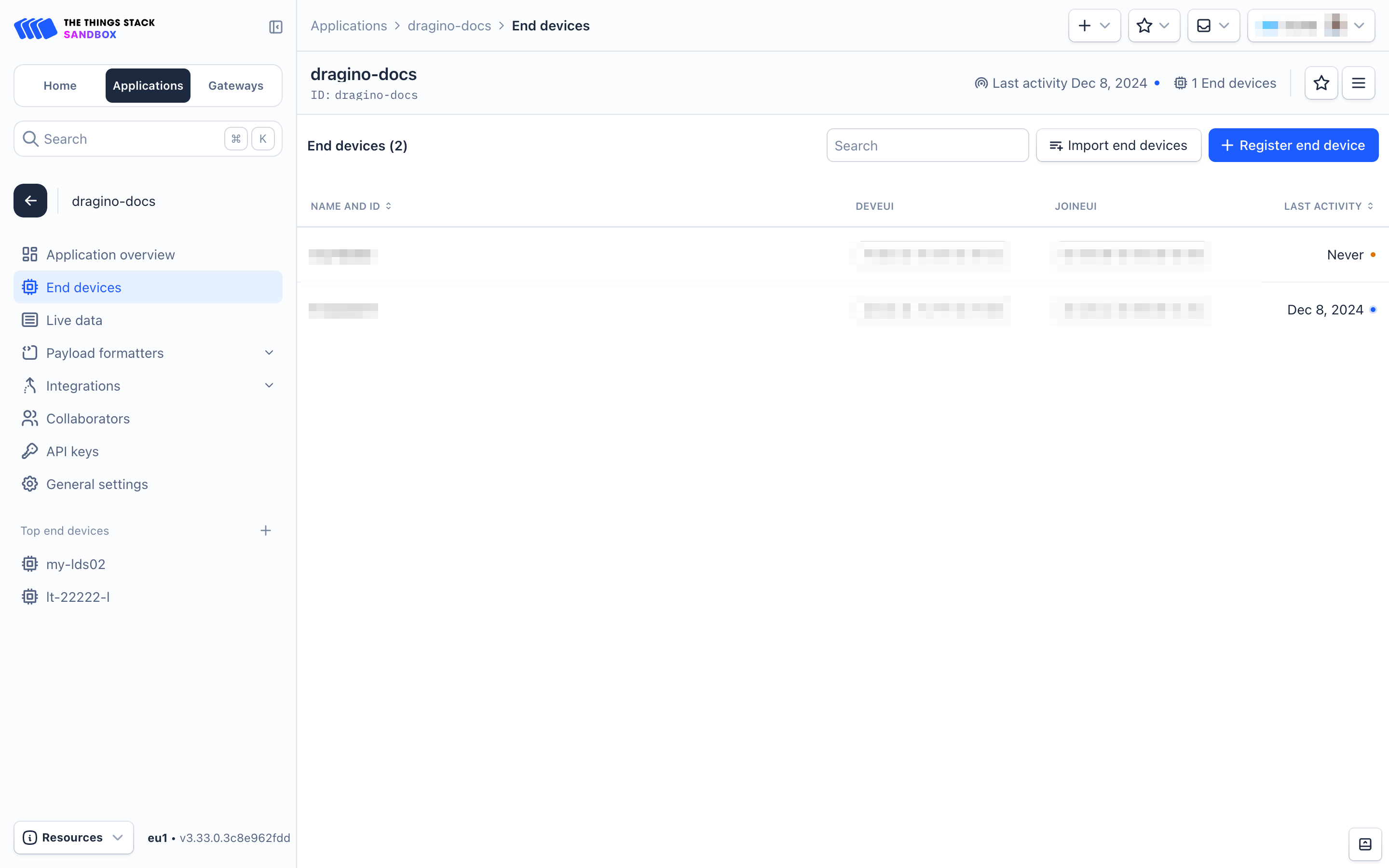
- Go to your application's page and click on the End devices in the left menu.
- On the End devices page, click on + Register end device.
- Two registration options are available:
- Using the LoRaWAN Device Repositoty
- Manual registration
4.2.2 Using the LoRaWAN Device Repository
- On the Register end device page:
- Select the option Select the end device in the LoRaWAN Device Repository under Input method.
- Select the End device brand, Model, Hardware version, Firmware version, and Profile (Region) from the respective dropdown lists.
- End device brand: Dragino Technology Co., Limited
- Model: LWL02 - Door Sensor
- Hardware ver: Unknown
- Firmware ver: 1.6
- Profile (Region): Select the region that matches your device.
- Select the Frequency plan that matches your device from the Frequency plan dropdown list.
- Enter the AppEUI in the JoinEUI field and click the Confirm button. If The Things Stack accepts the JoinEUI you provided, it will display the message 'This end device can be registered on the network.


- In the DevEUI field, enter the DevEUI.
- In the AppKey field, enter the AppKey.
- In the End device ID field, enter a unique name for your LDS02 within this application.
- Under After registration, select the View registered end device option.
- Click Register end device button.

- You will be navigated to the Device overview page.
- Click on the Live Data tab and then Power on the LWL02. It will first join The Things Stack network server. You can confirm this by looking for the Join-request and Join-accept messages. After successfully joining the network, the LWL02 will start sending uplink messages to The Things Stack, and you can see them in the Live Data panel.

4.3 Uplink Payload
The uplink payload is a total of 10 bytes.
| Size(bytes) | 2 | 1 | 3 | 3 | 1 |
| value | Status&BAT | MOD | Total_water_leak_events | Last water leak duration (unit:min) | Alarm status (Only used in |
Example:

The payload decoder for The Things Stack can be downloaded from: https://github.com/dragino/dragino-end-node-decoder
4.4 Downlink Payload
| Downlink Control Type | Type Code | Downlink payload size(bytes) |
|---|---|---|
| TDC (Transmit Time Interval—Keep Alive Interval) | 0x01 | 4 |
| RESET | 0x04 | 2 |
| Set confirmed mode | 0x05 | 2 |
| Clear Counting | 0xA6 | 2 |
| Enable/Disable Alarm | 0xA7 | 2 |
| Control ADR/DR | 0xA8 | 3 |
| Set Alarm Timeout | 0xA9 | 4 |
The following image illustrates how to send a downlink payload from The Things Stack.

Type Code 0x01
For example, if the payload is 0100003C, the LWL02's Keep Alive interval is set to 0x00003C (60 seconds).
Type Code 0x04
For example, if the payload is 0x04FF, it resets the LWL02.
Type Code 0x05
- The payload 0x05 00 sets the uplink to LoRaWAN unconfirmed mode.
- The payload 0x05 01 sets the uplink to LoRaWAN confirmed mode
Type Code 0xA6
The payload 0xA601 is used to "clear the counting." For the LWL02, it resets both the count numbers and the time.
Type Code 0xA7
- The payload 0xA7 01 is equivalent to AT+DISALARM=1.
- The payload 0xA7 00 is Equivalent to AT+DISALARM=0.
Type Code 0xA8
Downlink Payload Format: 0xA8 AA BB
- 0xA8: Type code
- AA:
- 1: Enable ADR
- 0: Disable ADR (same as the AT+CADR command)
- BB: Set DR (same as AT+CDATARATE; only valid after ADR = 0)
Example: 0xA8 00 02: Set ADR = 0 and DR = 2
Type Code 0xA9
For more information, see Alarm Base Timeout.
4.5 Integrate with Datacake
Datacake provides a human friendly interface to show the sensor data, once we have data in TTN V3, we can use Datacake to connect to TTN V3 and see the data in Datacake. Below are the steps:
Step 1: Be sure that your device is programmed and properly connected to the network at this time.
Step 2: To configure the Application to forward data to Datacake you will need to add integration. To add the Datacake integration, perform the following steps:


Step 3: Create an account or log in Datacake.
Step 4: Search LWL02 and add DevEUI.

4.6 Alarm Based on Timeout
The LWL02 can monitor the timeout for a status change. This feature can be used to monitor events, such as the duration of water leakage, and more.
(This command is specifically applicable to LDS02. For the LWL02, this command can only enable the alarm, but the alarm time is fixed at 10 minutes)
You can configure this feature using the following:
AT Command Configuration:
- AT+TTRIG=1,30 --> When the status changes from "close" to "open," the LWL02 remains in the "open" status for more than 30 seconds. Then it will send an uplink packet. The alarm bit (the lowest bit of the 10th byte of the payload) in this uplink packet is set to 1.
- AT+TTRIG=0,0 --> Default value, disables the timeout alarm.
Downlink Command Configuration:
Command: 0xA9 AA BB CC
- 0xA9: Type Code
- AA: Status to be monitored
- BB CC: Timeout
If you send 0xA9 01 00 1E, it is equivalent to AT+TTRIG=1,30.
Or, if you send 0xA9 00 00 00, it is equivalent to AT+TTRIG=0,0 (disables the timeout alarm).
4.7 LED Indicators
| Action | LED behavior |
|---|---|
| Power On | GREEN LED on for 1s, RED LED on for 1s, BLUE LED on for 1s |
| Joined successfully | GREEN LED on for 5s |
| Send an uplink message | GREEN LED blinks once |
| Receive a downlink message | BLUE LED blinks once |
5. Battery
The LWL02 is equipped with 2 AAA LR03 batteries.
5.1 Replacing Batteries
The LDS02 is equipped with 2 x AAA LR03 batteries. If the batteries are running low (showing 2.1V on the platform), the user can buy generic AAA batteries and replace them.
Note:
- The LDS02 doesn’t have any screws; you can use a nail to open it from the middle.
- Make sure the direction is correct when installing the AAA batteries.
Important Note: Ensure you use new AAA LR03 batteries, and that the battery surfaces are not damaged.
Example of AAA LR03 battery:

5.2 Power Consumption Analysis
Dragino battery-powered products all run in Low Power mode. You can refer to the guidelines from this link to estimate battery life.
6. Use AT Commands
6.1 Access AT Commands
The LWL02 supports an AT command set. You can use a USB to TTL adapter to configure the LWL02 via AT commands, as shown below.

On the PC, the user needs to set the serial tool (such as PuTTY or SecureCRT) baud rate to 115200 to access the serial console of the LWL02. Below is the output for reference:
The AT command access password is 123456.

Each AT command needs to have an ENTER key pressed at the end before sending.
When entering the first command, the RED LED will turn on, and the user can now input AT commands. After entering all the required AT commands, input AT+CLPM=1 to set the device to Low Power mode, and the RED LED will turn off.
More details can be found in the AT Command Manual.
7. FAQ
7.1 How to upgrade the image?
You can upgrade the LWL02 for bug fixes, new features, or to change the working region. The upgrade instructions are here: LDS02/LWL02 Update method.
7.2 How to change the LoRa Frequency Bands/Region?
If you have the US915 frequency and want to change it to the AS923 frequency, you can follow the instructions for upgrading the image in how to upgrade image section. When downloading the image, select the required file.
7.3 Can I disable uplinks for each event to save battery life?
Yes, you can use one of the method below:
Via AT Command:
AT+DISALARM=1 : The end node will only send packets during the TDC time.
AT+DISALARM=0 : The end node will send packets either during the TDC time or when there is a status change in the door sensor.
Via LoRaWAN downlink Command:
0xA701 : Equivalent to AT+DISALARM=1
0xA700 : Equivalent to AT+DISALARM=0
7.4 How can I change the Subband for LWL02?
Before v1.6 firmware:
LDS02 operates in Subband 2 by default in the AU915/US915 band. If the LoRaWAN server operates on another subband, LDS02 may have trouble joining the server. In this case, the user can use the AT command to change the subband. See the AT Command chapter for hardware connection details. Below are the steps to change the subband:
- Press the reset button.
- Send the password 123456.
- Send the command: AT+CFREQBANDMASK=0006 (use 0001 for Subband 1, 0002 for Subband 2, etc.).
- Press the reset button to restart and switch to the new subband.
Example output:
[3369]DRAGINO LWL01 Device
[3370]Frequency Band: US915 v1.5
[3373]OTAA
[3374]DevEui= 7896785455246354
[3377]class type A
[3379]freq mode intra
[3381]scan chn mask 0x0002 --> use subband 2
LM502:~# [10793]txDone
123456 --> ENTER PASSWORD
Correct Password
[105115]rxTimeOut
AT+CFREQBANDMASK=0001 --> Change to Subband1
OK
[3371]DRAGINO LWL01 Device
[3373]Frequency Band: US915 v1.5
[3376]OTAA
[3377]DevEui= 7896785455246354
[3380]class type A
[3382]freq mode intra
[3384]scan chn mask 0x0001 --> reboot and works on Subband1 now
Since firmware v1.6:
LDS02 works with the channel mask 0x0000, which covers all subbands. Therefore, there is no need to use AT commands to change the subband, and it will work for every subband.
7.5 My sensor worked for Helium AU915 before, but now it doesn't work. Why?
This is a sub-band issue. See chapter 7.4. Helium changed the sub-band for AU915 from subband 2 to subband 6, which caused the sensor to stop working.
7.6 Why do I see different working temperatures for the device?
The working temperature range of the device depends on the battery the user chooses.
- A standard AAA battery can support a working range of -10°C to 50°C.
- A special AAA battery can support a working range of -40°C to 60°C. For example, Energizer L92https://data.energizer.com/pdfs/l92.pdf
8. Ordering Information
Part Number: LWL02-XXX
XXX:
- EU433: frequency bands EU433
- EU868: frequency bands EU868
- KR920: frequency bands KR920
- CN470: frequency bands CN470
- AS923: frequency bands AS923
- AU915: frequency bands AU915
- US915: frequency bands US915
- IN865: frequency bands IN865
9. Packaging Information
Package Includes:
- LWL02 x 1
10. Support
- Support is provided Monday to Friday, from 09:00 to 18:00 GMT+8. Due to different time zones, we cannot offer live support. However, your questions will be answered as soon as possible during the aforementioned hours.
- Please provide as much information as possible regarding your inquiry (e.g., product models, a detailed description of the problem, and steps to replicate it), and send an email to support@dragino.com.