LTS5 LoRa HMI Touch Screen
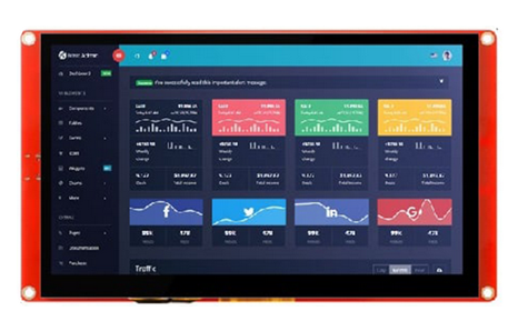
Table of Contents:
- 1. Introduction
- 2. Getting Start with Hello World
- 3. Example Project 1: LoRa Central Display
- 4. Example Project 2: LoRaWAN RS485 Alarm
- 6. FAQ
- 7. Order Info
- 8. Support
- 9. Reference material
- 10. FCC Warning
1. Introduction
1.1 What is LTS5 LoRa HMI touch screen
LTS5 is a LoRa / LoRaWAN HMI Touch Screen designed for display purpose of IoT project. It have a 5.0" HMI touch screen, and support WiFi, Bluetooch, LoRa wireless protocol.
LTS5 is an Open Source software project. The MCU is ESP32 and Dragino LA66 LoRa module. There are lots of development source for ESP32 which can greatly reduce the development time.
The HMI touch screen of LTS5 supports drap & drop design. Developer can use SquareLine to easily customize the display UI for different application.
LTS5 use LA66 LoRa module, this module can be program to support private LoRa protocol or LoRaWAN protocol.
1.2 Features
- ESP32-WROOM MCU + Dragino LA66 LoRa Module
- Support Private LoRa protocol or LoRaWAN protocol
- Support WiFi & BLE wireless protocol
- 5.0" HMI touch screen
- Support LVGL case. SquareLine program.
- Support RS485 Interface
- Open Source Project
- Wall Attachable.
- 5V DC power
- IP Rating: IP52
1.3 Specification
LoRa:
WiFi:
- 802.11b/g/n
- Up to 150 Mbps data rate in 802.11n mode
- Support A-MPDU and A-MSDU aggregation
- zero point four μ S protection interval
- Working channel center frequency range: 2412~2484 MHz
Bluetooth:
- Bluetooth V4.2 BR/EDR and Bluetooth LE standard
- Class-1, Class-2, and Class-3 transmitters.
- AFH
- CVSD and SBC
Display:
- 5.0 Inch , 800 x 480
- IPS Capacitive Touch SCreen
- RGB color.
- Display Area: 120.7*75.80 mm
1.4 Power Consumption
- External 5V DC power adapter
1.5 Storage & Operation Temperature
- Operation Temperature: -20 ~ 70°C (No Dew)
- Storage Temperature: -30 ~ 70°C (No Dew)
1.6 Applications
- Smart Buildings & Home Automation
- Logistics and Supply Chain Management
- Smart Metering
- Smart Agriculture
- Smart Cities
- Smart Factory
2. Getting Start with Hello World
2.1 About this demo
In this Getting Start Example, we will show how to design a simple Display UI and upload it to LTS5. This UI has a button , when user click the button. The Web UI will jump to a new page.
2.2 Install Software Running Environment
The ESP MCU can be developed using ESP-IDF, Arduino, or MicroPython. For this project, we utilize ESP-IDF for compilation and Visual Studio Code (VSCode) for editing.
2.2.1 Install VSCode and ESP-IDF extension
Firstly, download and install VSCode for your computer's operating system from the official website: Download Visual Studio Code - Mac, Linux, Windows.
Next, you need to install the ESP-IDF extension within VSCode. The detailed operation steps are illustrated in image 1.
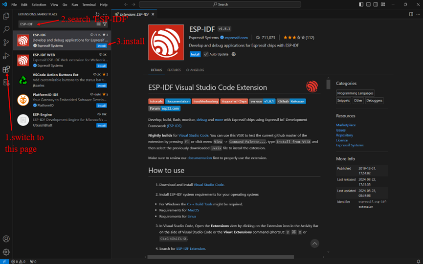
image 1 ESP-IDF extension install
Links for reference: Install ESP32 ESP-IDF on Windows and Integrate with VS code (esp32tutorials.com)
2.2.2 Install SquareLine Studio
The version we are utilizing for this software is 1.4.2. You can download it from the official link: SquareLine Studio - Download the current version of SquareLine Studio.
Please note that this software necessitates the registration of a license prior to usage, and various licenses come with distinct limitations. For instance, the free version imposes restrictions such as a limit of 1 component, 150 widgets, and 10 screens. However, for first-time downloads, you are granted unrestricted access for a period of 30 days without the need for immediate registration.
2.3 Simple usage of SquareLine Studio and export UI code
After launching and logging in to this software, create a project as shown in the following image 2. The version of LVGL is 8.3.11.
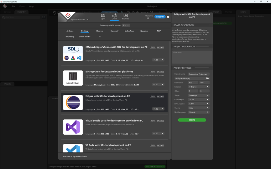
image 2 create a SquareLine project
Next, we need to make some settings for this project. By clicking in the specified order on image 3, we can see the page as shown in image 4.
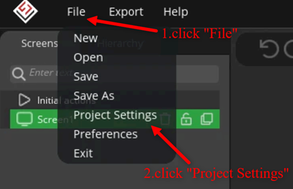
image 3 project settings
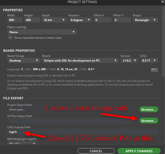
image 4 modify project settings
Now we can start to use this software. The steps for creating this UI are shown in image 5-10.
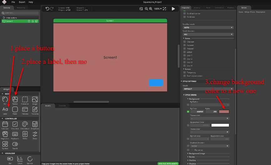
image 5 create a UI(1)
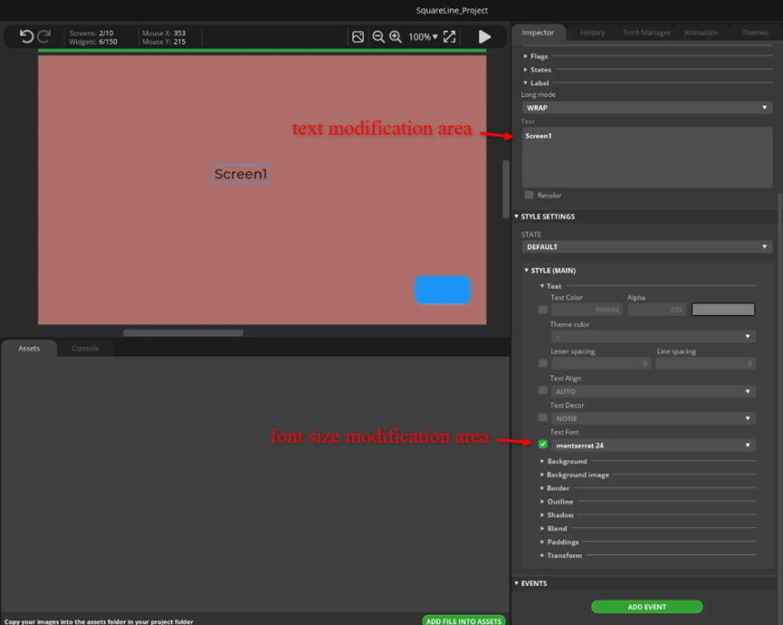
image 6 create a UI(2)
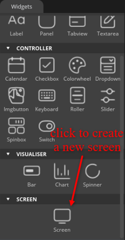
image 7 create a UI(3)
We repeat the steps of screen1 in screen2. Then we get screen2 as shown in image 8.
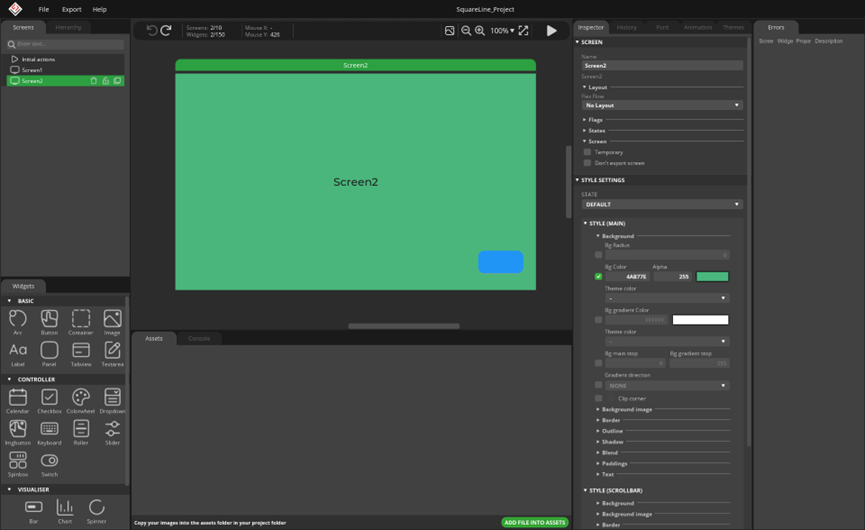
image 8 create a UI(4)
Finally, we add click event for screen change to button1 in screen1(shown in image 9) and button2 in screen2.
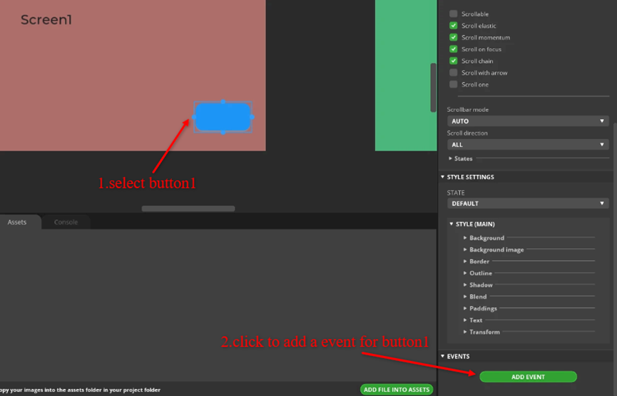
image 9 create a UI(5)
The event settings of button1 are as image 10 shown. The event adding operation of button2 is similar to button1.
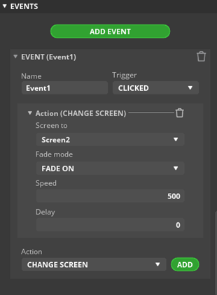
image 10 create a UI(6)
2.4 Integrate UI Code to ESP-IDF Project
To achieve the integrating, we first need to export the UI code, then make some modifications, and finally relocate the UI code to a specific position within the project.
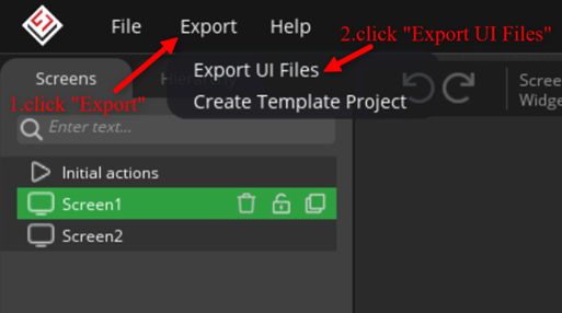
image 11 export UI file
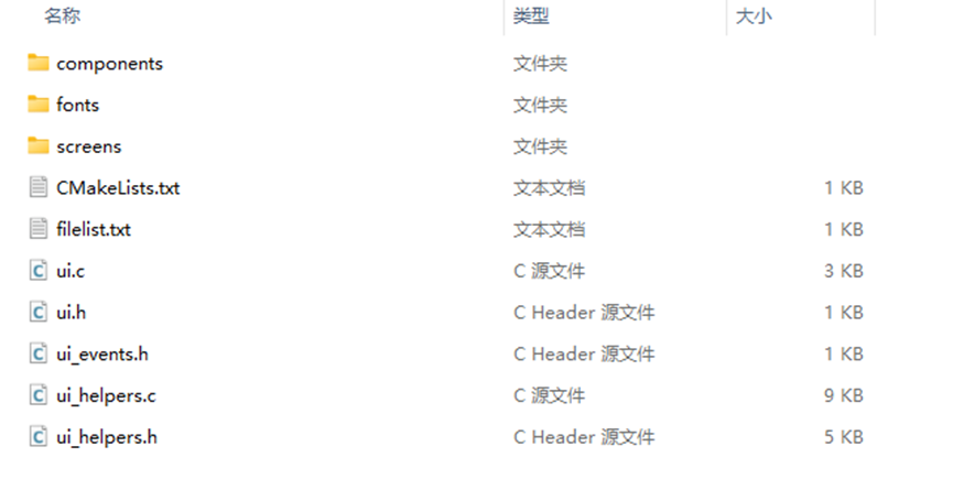
image 12 exported UI file
Create a empty directory entitled ‘ui’ in path “basic_prj/app_components/ui/”, and then copy all UI code exported to this directory.

image 13 open CMakeLists.txt
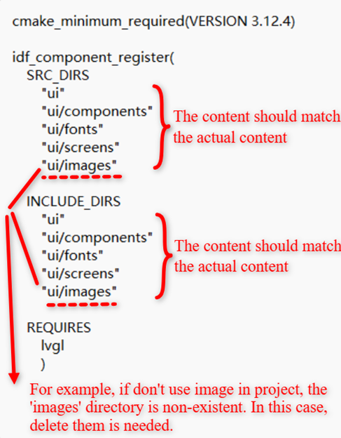
image 14 modify CMakeLists.txt
The last step of integrating is adding two lines of code in main.c file.
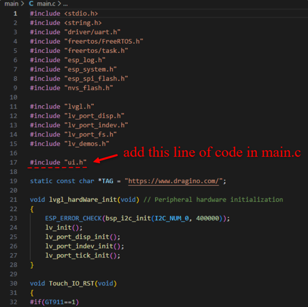
image 15 add “ui.h”
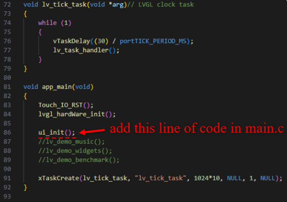
image 16 add “ui_init()”
2.5 Test Result
By pressing the button lying bottom right, the screen can switch to another as expected. This indicates that the UI file has been successfully integrated into the project and is now effective.
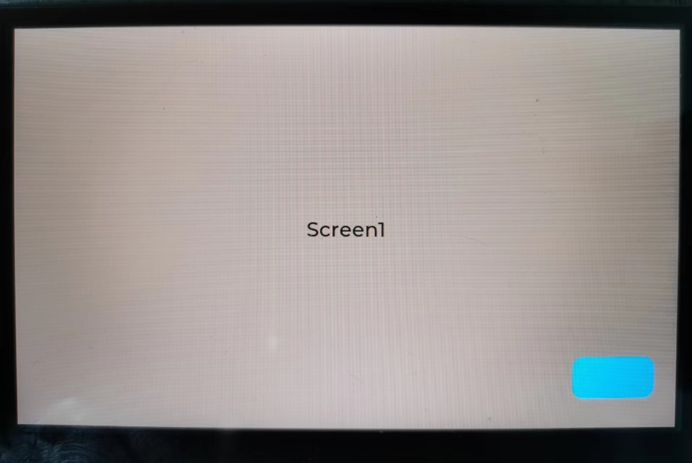
image 17 screen1
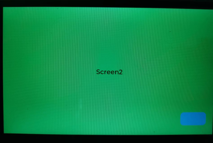
image 18 screen2
3. Example Project 1: LoRa Central Display

4. Example Project 2: LoRaWAN RS485 Alarm
6. FAQ
6.1
7. Order Info
7.1 Part Number
Part Number: LTS5
7.2 Packing Info
Package Includes:
- LTS5 HMI Touch Screen
- 5V,2A DC Power Adapter.
- USB Type C Program Cable
8. Support
- Support is provided Monday to Friday, from 09:00 to 18:00 GMT+8. Due to different timezones we cannot offer live support. However, your questions will be answered as soon as possible in the before-mentioned schedule.
- Provide as much information as possible regarding your enquiry (product models, accurately describe your problem and steps to replicate it etc) and send a mail to support@dragino.com.
9. Reference material
- Datasheet
- Source Code
- Mechinical
10. FCC Warning
This device complies with part 15 of the FCC Rules.Operation is subject to the following two conditions:
(1) This device may not cause harmful interference;
(2) this device must accept any interference received,including interference that may cause undesired operation.
