LHT65-PIR Temperature/Humidity/PIR Sensor User Manual

Table of Contents:
- 1. Introduction
- 2. Connect LHT65N-PIR to IoT Server
- 3. Sensors and Accessories
- 4. Configure LHT65N-PIR via AT command or LoRaWAN downlink
- 5. Battery & How to replace
- 6. FAQ
- 7. Order Info
- 8. Packing Info
- 9. Reference material
- 10. FCC Warning
1. Introduction
1.1 What is LHT65N-PIR Temperature,Humidity & PIR Sensor
The Dragino LHT65N-PIR Temperature, Humidity & PIR sensor is a Long Range LoRaWAN Sensor.It includes a built-in Temperature & Humidity sensor and has an external PIR Probe. LHT65N-PIR can detect environment Temperature & Humdity, it also detects People Activity via PIR probe and them send these info to LoRaWAN IoT Server.
The LHT65N-PIR allows users to send data and reach extremely long ranges. It provides ultra-long range spread spectrum communication and high interference immunity whilst minimizing current consumption. It targets professional wireless sensor network applications such as irrigation systems, smart metering, smart cities, building automation, and so on.
LHT65N-PIR has a built-in 2400mAh non-chargeable battery which can be used for more than 5 years*.
LHT65N-PIR supports wireless configure & OTA update which make user easy to use.
LHT65N-PIR is fully compatible with LoRaWAN v1.0.3 Class A protocol, it can work with a standard LoRaWAN gateway.
**The actual battery life depends on how often to send data, please see battery analyzer chapter.
1.2 Features
- LoRaWAN v1.0.3 Class A protocol
- Frequency Bands: CN470/EU433/KR920/US915/EU868/AS923/AU915
- AT Commands to change parameters
- Remote configure parameters via LoRaWAN Downlink
- Support wireless OTA update firmware
- Firmware upgradeable via program port
- Built-in 2400mAh battery for up to 5 years of use.
- Built-in Temperature & Humidity sensor
- External PIR Sensor
- Tri-color LED to indicate working status
1.3 Specification
Built-in Temperature Sensor:
- Resolution: 0.01 °C
- Accuracy Tolerance : Typ ±0.3 °C
- Long Term Drift: < 0.02 °C/yr
- Operating Range: -40 ~ 85 °C
Built-in Humidity Sensor:
- Resolution: 0.04 %RH
- Accuracy Tolerance : Typ ±3 %RH
- Long Term Drift: < 0.02 °C/yr
- Operating Range: 0 ~ 96 %RH
External PIR Sensor:
- Base on BH1750 Illumination Sensor
- Cable Length : 50cm
- Resolution: 1 lx
- Range: 0-65535 lx
- Operating Range: -40 °C ~ 85 °C
2. Connect LHT65N-PIR to IoT Server
2.1 How does LHT65N-PIR work?
LHT65N-PIR is configured as LoRaWAN OTAA Class A sensor by default. Each LHT65N-PIR is shipped with a worldwide unique set of OTAA keys. To use LHT65N-PIR in a LoRaWAN network, first, we need to put the OTAA keys in LoRaWAN Network Server and then activate LHT65N-PIR.
If LHT65N-PIR is within the coverage of this LoRaWAN network. LHT65N-PIR can join the LoRaWAN network automatically. After successfully joining, LHT65N-PIR will start to measure environment temperature, humidity & people activity, and start to transmit sensor data to the LoRaWAN server. The default period for each uplink is 20 minutes.
2.2 How to Activate LHT65N-PIR?
The LHT65N-PIR has two working modes:
- Deep Sleep Mode: LHT65N-PIR doesn't have any LoRaWAN activation. This mode is used for storage and shipping to save battery life.
- Working Mode: In this mode, LHT65N-PIR works as LoRaWAN Sensor mode to Join LoRaWAN network and send out the sensor data to the server. Between each sampling/tx/rx periodically, LHT65N-PIR will be in STOP mode (IDLE mode), in STOP mode, the PIR sensor is still working to detect people activity in low power consumption.
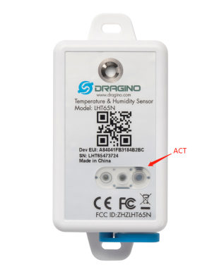
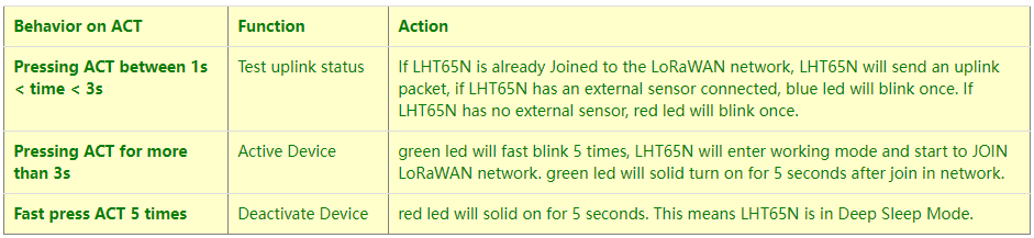
The LHT65N-PIR is set in deep sleep mode by default; The ACT button on the front is to switch to different modes:
2.3 Example to join LoRaWAN network
This section shows an example of how to join the TTN V3 LoRaWAN IoT server. Use with other LoRaWAN IoT servers is of a similar procedure.

Assume the LPS8v2 is already set to connect to TTN V3 network, So it provides network coverage for LHT65N-PIR. Next we need to add the LHT65N-PIR device in TTN V3:
2.3.1 Step 1: Create Device n TTN
Create a device in TTN V3 with the OTAA keys from LHT65N-PIR.
Each LHT65N-PIR is shipped with a sticker with its device EUI, APP Key and APP EUI as below:

User can enter these keys in the LoRaWAN Server portal. Below is TTN V3 screenshot:
Add APP EUI in the application.


Note: LHT65N-PIR use same payload decoder as LHT65.
Input APP EUI, APP KEY and DEV EUI:

2.3.2 Step 2: Activate LHT65N-PIR by pressing the ACT button for more than 5 seconds.
Use ACT button to activate LHT65N-PIR and it will auto-join to the TTN V3 network. After join success, it will start to upload sensor data to TTN V3 and user can see in the panel.
2.4 Uplink Payload ( Fport=2)
The uplink payload includes totally 11 bytes. Uplink packets use FPORT=2 and every 20 minutes send one uplink by default.
After each uplink, the BLUE LED will blink once.
Size(bytes) | 2 | 2 | 2 | 1 | 4 |
|---|---|---|---|---|---|
Value | Ext # |
- The First 6 bytes: has fix meanings for every LHT65N-PIR.
- The 7th byte (EXT #): defines the external sensor model. It can be 0x0A for LHT65N-PIR
- The 8th byte: Alarm Bit (if this uplink is from periodically or movement)
- The 9th ~ 11st byte: Movement Detect Count.
2.4.1 Decoder in TTN V3
When the uplink payload arrives TTNv3, it shows HEX format and not friendly to read. We can add LHT65N-PIR decoder in TTNv3 for friendly reading.
Below is the position to put the decoder and LHT65N-PIR decoder can be download from here: https://github.com/dragino/dragino-end-node-decoder

2.4.2 BAT-Battery Info
These two bytes of BAT include the battery state and the actually voltage


Check the battery voltage for LHT65N-PIR.
- BAT status=(0xcba4>>14)&0xFF=11(B),very good
- Battery Voltage =0xCBF6&0x3FFF=0x0BA4=2980mV
2.4.3 Built-in Temperature

- Temperature: 0x0ABB/100=27.47℃

- Temperature: (0xF5C6-65536)/100=-26.18℃
2.4.4 Built-in Humidity

- Humidity: 0x025C/10=60.4%
2.4.5 Ext value
2.4.5.1 Ext=0x0A, PIR Sensor

2.4.5.2 Ext Value
There are 4 bytes in Ext Value field.
Bit0 of byte 8th shows if this uplink is generate by PIR activity.
The 8th byte | Bit 1~7 | Bit 0 |
|---|---|---|
Value | Reserve | 0: Normal Uplink 1: Uplink by activity detected |
Note: Uplink by activity is disable by default.
The 9th ~ 11st byte: Movement Detect Count.
0x00 E5 09 : Total detect 58633 activity since end node start.
2.5 Show data on Datacake
Datacake IoT platform provides a human-friendly interface to show the sensor data, once we have sensor data in TTN V3, we can use Datacake to connect to TTN V3 and see the data in Datacake. Below are the steps:
Step 1: Be sure that your device is programmed and properly connected to the LoRaWAN network.
Step 2: Configure your Application to forward data to Datacake you will need to add integration. Go to TTN V3 Console --> Applications --> Integrations --> Add Integrations.
Add Datacake:

Select default key as Access Key:

In Datacake console (https://datacake.co/) , add LHT65 device.


2.8 LED Indicator
The LHT65N-PIR has a triple color LED which for easy showing different stage .
While user press ACT button, the LED will work as per LED status with ACT button.
In a normal working state:
- For each uplink, the BLUE LED or RED LED will blink once.
BLUE LED when external sensor is connected. - RED LED when external sensor is not connected
- For each success downlink, the PURPLE LED will blink once
2.9 installation

3. Sensors and Accessories
3.1 E2 Extension Cable


1m long breakout cable for LHT65N-E5. Features:
Use for AT Command
Update firmware for LHT65N-PIR

4. Configure LHT65N-PIR via AT command or LoRaWAN downlink
Use can configure LHT65N-E5 via AT Command or LoRaWAN Downlink.
AT Command Connection: See FAQ.
LoRaWAN Downlink instruction for different platforms: IoT LoRaWAN Server
There are two kinds of commands to configure LHT65N-E5, they are:
General Commands.
These commands are to configure:
General system settings like: uplink interval.
LoRaWAN protocol & radio-related commands.
They are the same for all Dragino Devices which supports DLWS-005 LoRaWAN Stack(Note**). These commands can be found on the wiki: End Device Downlink Command
Commands special design for LHT65N-E5
These commands are only valid for LHT65N-E5, as below:
4.1 Set Transmit Interval Time
Feature: Change LoRaWAN End Node Transmit Interval.
AT Command: AT+TDC

Downlink Command: 0x01
Format: Command Code (0x01) followed by 3 bytes time value.
If the downlink payload=0100003C, it means set the END Node's Transmit Interval to 0x00003C=60(S), while type code is 01.
- Example 1: Downlink Payload: 0100001E // Set Transmit Interval (TDC) = 30 seconds
- Example 2: Downlink Payload: 0100003C // Set Transmit Interval (TDC) = 60 seconds
4.2 Currently only supports E5
Feature: Set device password, max 9 digits
AT Command: AT+EXT
| Command Example | Function | Response |
| AT+EXT=? | Get or Set external sensor model | 5 OK |
| AT+EXT=5 | Set external sensor mode to 5 | |
Downlink Command:0xA2
Total bytes: 2 bytes
Example:
- 0xA205: Set external sensor type to E5
4.3 Set to sleep mode
Feature: Set device to sleep mode
- AT+Sleep=0 : Normal working mode, device will sleep and use lower power when there is no LoRa message
- AT+Sleep=1 : Device is in deep sleep mode, no LoRa activation happen, used for storage or shipping.
AT Command: AT+SLEEP

Downlink Command:
- There is no downlink command to set to Sleep mode.
5. Battery & How to replace
5.1 Battery Type
LHT65N-E5 is equipped with a 2400mAH Li-MnO2 (CR17505) battery . The battery is an un-rechargeable battery with low discharge rate targeting for up to 8~10 years use. This type of battery is commonly used in IoT devices for long-term running, such as water meters.
The discharge curve is not linear so can't simply use percentage to show the battery level. Below is the battery performance.

The minimum Working Voltage for the LHT65N-E5 is ~ 2.5v. When battery is lower than 2.6v, it is time to change the battery.
5.2 Replace Battery
LHT65N-E5 has two screws on the back, Unscrew them, and changing the battery inside is ok. The battery is a general CR17450 battery (3.0v). Any brand should be ok.


5.3 Battery Life Analyze
Dragino battery-powered products are all run in Low Power mode. User can check the guideline from this link to calculate the estimated battery life:
https://www.dragino.com/downloads/downloads/LoRa_End_Node/Battery_Analyze/DRAGINO_Battery_Life_Guide.pdf
A full detail test report for LHT65N-E5 on different frequency can be found at : https://www.dropbox.com/sh/r2i3zlhsyrpavla/AAB1sZw3mdT0K7XjpHCITt13a?dl=0
6. FAQ
6.1 How to use AT Command?
LHT65N-E5 supports AT Command set.User can use a USB to TTL adapter plus the Program Cable to connect to LHT65 for using AT command, as below.


In PC, User needs to set serial tool(such as putty, SecureCRT) baud rate to 9600 to access to access serial console for LHT65N-E5. The AT commands are disable by default and need to enter password (default:123456) to active it. Timeout to input AT Command is 5 min, after 5-minute, user need to input password again. User can use AT+DISAT command to disable AT command before timeout.

AT Command List is as below:
AT+<CMD>? : Help on <CMD>
AT+<CMD> : Run <CMD>
AT+<CMD>=<value> : Set the value
AT+<CMD>=? : Get the value
AT+DEBUG: Set more info output
ATZ: Trig a reset of the MCU
AT+FDR: Reset Parameters to Factory Default, Keys Reserve
AT+DEUI: Get or Set the Device EUI
AT+DADDR: Get or Set the Device Address
AT+APPKEY: Get or Set the Application Key
AT+NWKSKEY: Get or Set the Network Session Key
AT+APPSKEY: Get or Set the Application Session Key
AT+APPEUI: Get or Set the Application EUI
AT+ADR: Get or Set the Adaptive Data Rate setting. (0: off, 1: on)
AT+TXP: Get or Set the Transmit Power (0-5, MAX:0, MIN:5, according to LoRaWAN Spec)
AT+DR: Get or Set the Data Rate. (0-7 corresponding to DR_X)
AT+DCS: Get or Set the ETSI Duty Cycle setting - 0=disable, 1=enable - Only for testing
AT+PNM: Get or Set the public network mode. (0: off, 1: on)
AT+RX2FQ: Get or Set the Rx2 window frequency
AT+RX2DR: Get or Set the Rx2 window data rate (0-7 corresponding to DR_X)
AT+RX1DL: Get or Set the delay between the end of the Tx and the Rx Window 1 in ms
AT+RX2DL: Get or Set the delay between the end of the Tx and the Rx Window 2 in ms
AT+JN1DL: Get or Set the Join Accept Delay between the end of the Tx and the Join Rx Window 1 in ms
AT+JN2DL: Get or Set the Join Accept Delay between the end of the Tx and the Join Rx Window 2 in ms
AT+NJM: Get or Set the Network Join Mode. (0: ABP, 1: OTAA)
AT+NWKID: Get or Set the Network ID
AT+FCU: Get or Set the Frame Counter Uplink
AT+FCD: Get or Set the Frame Counter Downlink
AT+CLASS: Get or Set the Device Class
AT+JOIN: Join network
AT+NJS: Get the join status
AT+SENDB: Send hexadecimal data along with the application port
AT+SEND: Send text data along with the application port
AT+RECVB: Print last received data in binary format (with hexadecimal values)
AT+RECV: Print last received data in raw format
AT+VER: Get current image version and Frequency Band
AT+CFM: Get or Set the confirmation mode (0-1)
AT+CFS: Get confirmation status of the last AT+SEND (0-1)
AT+SNR: Get the SNR of the last received packet
AT+RSSI: Get the RSSI of the last received packet
AT+TDC: Get or set the application data transmission interval in ms
AT+PORT: Get or set the application port
AT+DISAT: Disable AT commands
AT+PWORD: Set password, max 9 digits
AT+CHS: Get or Set Frequency (Unit: Hz) for Single Channel Mode
AT+CHE: Get or Set eight channels mode,Only for US915,AU915,CN470
AT+PDTA: Print the sector data from start page to stop page
AT+PLDTA: Print the last few sets of data
AT+CLRDTA: Clear the storage, record position back to 1st
AT+SLEEP: Set sleep mode
AT+EXT: Get or Set external sensor model
AT+BAT: Get the current battery voltage in mV
AT+CFG: Print all configurations
AT+WMOD: Get or Set Work Mode
AT+ARTEMP: Get or set the internal Temperature sensor alarm range
AT+CITEMP: Get or set the internal Temperature sensor collection interval in min
AT+SETCNT: Set the count at present
AT+RJTDC: Get or set the ReJoin data transmission interval in min
AT+RPL: Get or set response level
AT+TIMESTAMP: Get or Set UNIX timestamp in second
AT+LEAPSEC: Get or Set Leap Second
AT+SYNCMOD: Get or Set time synchronization method
AT+SYNCTDC: Get or set time synchronization interval in day
AT+PID: Get or set the PID
6.2 Where to use AT commands and Downlink commands
AT commands:

Downlink commands:
TTN:

Helium:

Chirpstack: The downlink window will not be displayed until the network is accessed


Aws:

6.3 How to change the uplink interval?
Please see this link: http://wiki.dragino.com/xwiki/bin/view/Main/How%20to%20set%20the%20transmit%20time%20interval/
6.4 How to use TTL-USB to connect PC to upgrade firmware?
Step1: Install TremoProgrammer first.

Step2:wiring method.
First connect the four lines;
 ,
,
Then use DuPont cable to short circuit port3 and port1, and then release them, so that the device enters bootlaod mode.

Step3:Select the device port to be connected, baud rate and bin file to be downloaded.

Click the start button to start the firmware upgrade.
When this interface appears, it indicates that the download has been completed.

Finally, unplug the DuPont cable on port4, and then use the DuPont cable to short circuit port3 and port1 to reset the device.
7. Order Info
Part Number: LHT65N-PIR-XX
XX : The default frequency band
- AS923: LoRaWAN AS923 band
- AU915: LoRaWAN AU915 band
- EU433: LoRaWAN EU433 band
- EU868: LoRaWAN EU868 band
- KR920: LoRaWAN KR920 band
- US915: LoRaWAN US915 band
- IN865: LoRaWAN IN865 band
- CN470: LoRaWAN CN470 band
8. Packing Info
Package Includes:
- LHT65N-PIR Temperature/Humidity/PIR Sensor x 1
Dimension and weight:
- Device Size: 10 x 10 x 3.5 mm
- Device Weight: 120.5g
9. Reference material
10. FCC Warning
This device complies with part 15 of the FCC Rules.Operation is subject to the following two conditions:
(1) This device may not cause harmful interference;
(2) this device must accept any interference received, including interference that may cause undesired operation.