
Table of Contents:
- 1. Introduction
- 2. Quick Start
- 2.1 Access Configure Web UI
- 2.2 Typical Network Setup
- 2.3 Bridge LoRaWAN network to Modbus network
- Step 1: Configure the LoRa Radio to your area Frequency Plan
- Step 2: Copy the unique Gateway EUI & Configure the LoRaWAN Server address
- Step 3: Enable the Built-in LoRaWAN Network Server
- Step 4: Logging to the Built-in LoRaWAN Network Server
- Step 5: Register the gateway to the built-in ChirpStack
- Step 6: Register the Sensor-node to the built-in ChirpStack
- Step 7: Configure Modbus RTU Slave
- 3. Web Configure Pages
- 4. Build-in Server
1. Introduction
1.1 What is MS48-LR
The MS48-LR is an open-source LoRaWAN To Modbus Gateway. It lets you bridge LoRa wireless network to an IP network via WiFi , Ethernet or Cellular Network (via Optional 4G module). The LoRa wireless allows users to send data and reach extremely long ranges at low data rates.
The MS48-LR is fully compatible with LoRaWAN protocol. MS48-LR includes a built-in LoRaWAN Server and IoT server, User can connect virous LoRaWAN devices to MS48-LR, and use PLC to access these devices via Modbus network.
Different countries use different LoRaWAN frequency bands. MS48-LR has these bands pre-configured. Users can also customize the frequency bands to use in their own LoRa network.
MS48-LR supports remote management. System Integrator can easy to remote monitor the gateway and maintain it.
1.2 How does it work?
The MS48-LR can run as a Modbus RS485-RTU slave, which writes the data from the LoRaWAN sensor uplink data into the registers of the 03 function code

1.3 Specifications
Hardware System:
- CPU: Quad-core Cortex-A7 1.2Ghz
- RAM: 512MB
- eMMC: 4GB
Interface:
- 10M/100M RJ45 Ports x 1
- Multi-Channel LoRaWAN Wireless
- WiFi 802.11 b/g/n
- USB 2.0 host connector x 1
- Mini-PCI E connector x 1
- RS485 Interface x 1
- RS232 Interface x 1
LoRa Spec:
- Up to -140 dBm sensitivity with SX1250 Tx/Rx front-end
- 70 dB CW interferer rejection at 1 MHz offset
- Able to operate with negative SNR, CCR up to 9dB
- Emulates 49 x LoRa demodulators and 1 x (G)FSK demodulator
- Dual digital TX & RX radio front-end interfaces
- 10 programmable parallel demodulation paths
- Dynamic data-rate (DDR) adaptation
- True antenna diversity or simultaneous dual-band operation
Cellular 4G LTE (optional):
- Quectel: EC25 LTE module
- Standard Size SIM Slot
- 2 x 4G Sticker Antenna.
- Up to 150Mbps downlink and 50Mbps uplink data rates
- Worldwide LTE,UMTS/HSPA+ and GSM/GPRS/EDGE coverage
- MIMO technology meets demands for data rate and link reliability in modem wireless communication systems
Operating Condition:
- Work Temperature: -20 ~ 70°C
- Storage Temperature: -20 ~ 70°C
- Power Input: 12V, 2A, DC
1.4 Features
- Open Source Debian system
- Managed by Web GUI, SSH via WAN or WiFi
- Remote Management
- Auto-provisioning for batch deployment and management
- LoRaWAN Gateway
- 10 programmable parallel demodulation paths
- Pre-configured to support different LoRaWAN regional settings.
- Allow customizing LoRaWAN regional parameters.
- Different kinds of LoRaWAN Connections such as
- Semtech UDP Packet Forwarder
- LoRaWAN Basic Station
- ChirpStack-Gateway-Bridge (MQTT)
- Built-in ChirpStack local LoRaWAN server
- Built-in Node-Red local Application server
- Act as Modbus Slave mode
1.5 LED Indicators
MS48-LR has totally four LEDs, They are:
➢ LED 1 (ETH LED): This GREEN LED will blink GREEN when the ETH port is connecting
➢ LED 2 (RET LED): This GREEN LED will show different colors in different states:
✓ SOLID GREEN: When the Long press 4-5s Toggle button,the device will reload the Network and Initialize wifi configuration,This GREEN LED will SOLID GREEN Until the reload is finished.
✓ BLINKING GREEN: When the Long press 10s Toggle button,the device will restore the factory settings,This GREEN LED will BLINKIND GREEN Until the restore is finished.
➢ LED 3: This GREEN LED is undefined
➢ LED 4 (Power LED): This GREEN LED will be solid if the device is properly powered
➢ LED 5 (WIFI LED): This LED shows the WIFI interface connection status.
✓ SOLID GREEN: The device enables the WiFi WAN Client and connects to the WiFi successfully.
✓ BLINKING GREEN: The device's WiFi WAN Client connection is unsuccessful.
✓ OFF: The device WiFi WAN Client is not enabled.
➢ LED 6 (SYS LED): This GREEN LED will show different colors in different states:
✓ SOLID GREEN: The device is alive with a LoRaWAN server connection.
✓ BLINKING GREEN: a) no LoRaWAN Connection. or b) Device is in booting stage, in this stage, it will BLINKING GREEN for several seconds and then with BLINKING GREEN together
✓ OFF: Device doesn't have an Internet connection.
1.6 Button Instruction
The MS48-LR has two black buttons, which are:
RST: Press and release, and the gateway will restart
LED status: All LEDs are off except for the LED 4 (Power LED).
Toggle:
➢ Long press 4-5s : the gateway will reload the Network and Initialize wifi configuration
LED status: LED 2 (RET LED) will SOLID GREEN Until the reload is finished.
➢ Long press more than 10s: the gateway will restore the factory settings.
LED status: LED 2 (RET LED) will BLINKIND GREEN Until the restore is finished.
1.7 Installation


2. Quick Start
2.1 Access Configure Web UI
Web Interface
Open a browser on the PC and type the MS48-LR ip address (depends on your connect method)
http://IP_ADDRESS or http://172.31.255.254(Fallback IP)
You will see the login interface of MS48-LR as shown below.
The account details for Web Login are:
User Name: root
Password: dragino
2.2 Typical Network Setup
2.2.1 Overview
MS48-LR supports flexible network set up for different environment. This section describes the typical network topology can be set in MS48-LR. The typical network set up includes:
- WAN Port Internet Mode
- WiFi Client Mode
- Cellular Mode
2.2.2 Use WAN port to access Internet
By default, the MS48-LR is set to use the WAN port to connect to an upstream network. When you connect the MS48-LR's WAN port to an upstream router, MS48-LR will get an IP address from the router and have Internet access via the upstream router. The network status can be checked in the home page:
2.2.3 Access the Internet as a WiFi Client
In the WiFi Client Mode, MS48-LR acts as a WiFi client and gets DHCP from an upstream router via WiFi.
The settings for WiFi Client is under page Network --> Wi-Fi
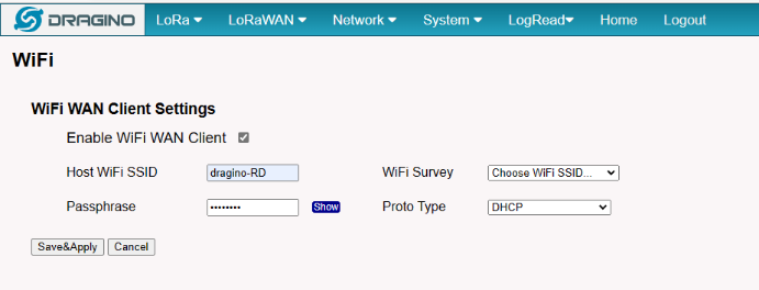
In the WiFi Survey Choose the WiFi AP, and input the Passphrase then click Save & Apply to connect.
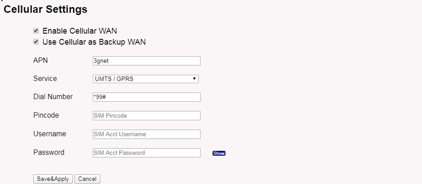
2.2.4 Use built-in 4G modem for internet access
Users can see whether MS48-LR has EC25 on the label of the gateway to determine whether there is 3G/4G Cellular modem.
If the MS48-LR has 3G/4G Cellular modem, user can use it as main internet connection or back up.
First, install the Micro SIM card as below direction
Second, Power off/ ON MS48-LR to let it detect the SIM card.


The set up page is Network --> Cellular
While use the cellular as Backup WAN, device will use Cellular for internet connection while WAN port or WiFi is not valid and switch back to WAN port or WiFi after they recover.
2.2.5 Check Internet connection
In the Home page, we can check the Internet connection.
- GREEN Tick
 : This interface has Internet connection.
 - Yellow Tick
 : This interface has IP address but don't use it for internet connection.
 - RED Cross
 : This interface doesn't connected or no internet.
2.3 Bridge LoRaWAN network to Modbus network
Step 1: Configure the LoRa Radio to your area Frequency Plan
The Frequency Plan has to be set the same as the Sensor node Frequency Plan.

Step 2: Copy the unique Gateway EUI & Configure the LoRaWAN Server address
Every MS48-LR has a unique gateway EUI. The ID can be found on the LoRaWAN Semtech page:

Step 3: Enable the Built-in LoRaWAN Network Server

Step 4: Logging to the Built-in LoRaWAN Network Server

Step 5: Register the gateway to the built-in ChirpStack
Copy Gateway EUI from the previous step to the following interface:

Step 6: Register the Sensor-node to the built-in ChirpStack
The gateway is already set up to connect to the built-in ChirpStack network, so we now need to configure the built-in ChirpStack.
Create a device in ChirpStack with the OTAA keys from LHT65N.
1). Add Device Profiles

2.) Add End Node Device
Create an Application
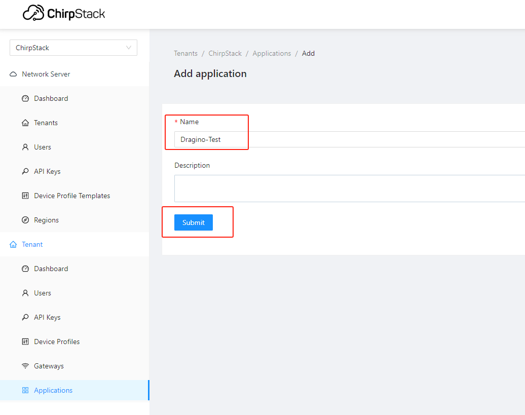
Add a device for the sensor node

Enter Device EUI, Join EUI(APP EUI)and APPKEY of the node Device, and select the Device profile added in the previous step


Step 7: Configure Modbus RTU Slave
The gateway can as a Modbus RTU slave to run, the user can set a range of the register to write a sensor node uplink data.
For example, there is a sensor node EUI is 70b3d57ed0051e22, the register start is 0xABCD and the register length is 14, which means the uplink data will be written to the register starting at 0xABCD register and the maximum write length not to exceed 14 registers.
So the sensor node 70b3d57ed0051e22 uplink data will be written to the 0xABCD - 0xABE1 register.
Note: Since the length of the payload is the same for different sensor nodes if The length of the data is greater than the configuration length, the data will be replaced with FFFF.
Enable Modbus Slave ---> Enable Slave
Show Sensor History ---> See the sensor data log
Slave Address ---> Set the slave address
Device EUI ---> Sensor node's EUI
Register Start ---> Setting the start register address to write the sensor node's data
Register Length ---> The maximum write length with register
Note: Only 1 sensor can be written in the range set by the registers

After the sensor node is active at the built-in server Chirpstack, the user can add it to this page and enable the Modbus RS485-RTU Slave.
Then MS48-LR will write the uplink data to the 03 code register and record the uplink data.
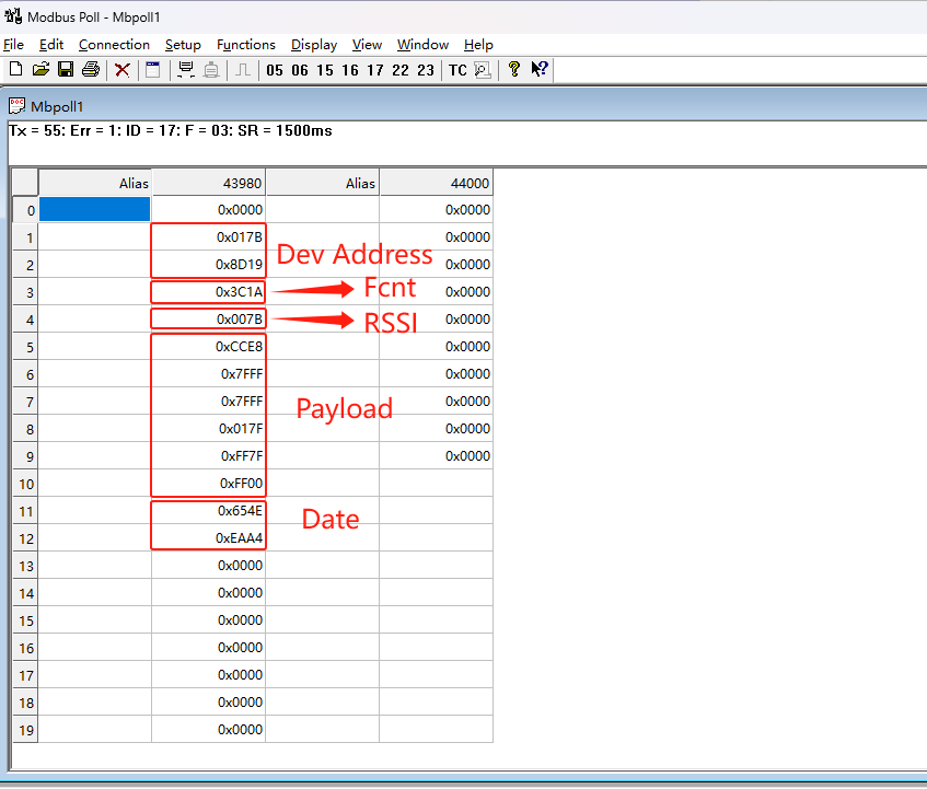
PLC read the MS48-LR register
Settings:
Function : 03 code
Bit rate : 9600
Parity bit : none
Stop bit : 1
Respone Timeout : Greater than 1500ms
History Data:
Click the Show Sensor History will launch to this page

3. Web Configure Pages
3.1 Home
Shows the system running status:
3.2 LoRa Settings
3.2.1 LoRa --> LoRa
This page shows the LoRa Radio Settings. There is a set of default frequency bands according to LoRaWAN protocol, and users can customize the band* as well.
Different MS48-LR hardware versions can support different frequency ranges:
- 868: valid frequency: 863Mhz ~ 870Mhz. for bands EU868, RU864, IN865, or KZ865.
- 915: valid frequency: 902Mhz ~ 928Mhz. for bands US915, AU915, AS923 or KR920
After the user choose the frequency plan, the user can see the actual frequency is used by checking the page LogRead --> LoRa Log

Note *: See this instruction for how to customize the frequency band: How to customized LoRaWAN frequency band - DRAGINO
3.3 LoRaWAN Settings
3.3.1 LoRaWAN --> LoRaWAN Semtech UDP
This page is for the connection set up to a general LoRaWAN Network server such as TTN, ChirpStack, etc.

3.3.2 LoRaWAN --> LoRaWAN Basic Station
This page is for the connection set up to the TTN Basic Station, AWS-IoT, etc.

Please see this instruction to know more detail and a demo for how to use of LoRaWAN Basic Station: Use of LoRaWAN Basic Station - DRAGINO
3.4 Network Settings
3.4.1 Network --> WiFi
Users can configure the wifi WAN and enable Wifi Access Point on this interface

3.4.2 Network --> System Status

3.4.3 Network --> Network
In the Network --> Network interface, Users can set the Ethernet WAN static ip address.

3.4.4 Network --> Cellular
In the Network --> Cellular interface, Users can Enable Cellular WAN and configure Celluar.
Note: APN cannot be empty.

After the configuration is complete, return to the Home interface and put the mouse on the Cell icon to check the Cellular state.
3.5 System
3.5.1 System --> System Overview
Shows the system info:
3.5.2 System --> System General
In the System-> System General interface, Users can customize the configuration System Password and set Timezone.
In addition, Users can customize the FallBack IP address.

3.5.3 System --> Backup/Restore

3.5.4 System --> Remoteit
In the System-> Remoteit interface, users can configure the gateway to be accessed remotely via Remote.it.
the users can refer to this link to configure them: Monitor & Remote Access Gateway

3.5.5 System --> Package Management
In the System --> Package Management interface, Users can check the current version of Core Packages.

4. Build-in Server
the default factory version of MS48-LR is installed with the built-in Applicant server: Node-Red, LoRaWAN Server: ChirpStack.
Note:
Path: Server --> Network Server
Server --> Application Server
Troubleshooting:
1. URL does not jump properly
For the ChirpStack, you can use the local IP address and the port is 8080 to access it.
For the Node-Red, you can use the local IP address and the port is 1880 to access it.
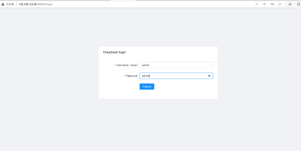
4.1 LoRaWAN Network Server -- ChirpStack
You can access the gateway's built-in LNS server of ChirpStack via the URL( http://<hostname>:8080 or http://<local-IPV4-address> ) in your browser.
Such as http://dragino-54ff12:8080 or http://<Local-IPV4-Address>
Login account:
Username : admin
Password: admin
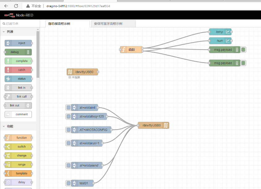
4.2 Application Server -- Node-Red
You can access the gateway's built-in AS server of Node-Red via the URL(http://<hostname>:1880 or http://<local-IPV4-address>) in your browser.
Such as http://dragino-54ff12:1880 or http://<Local-IPV4-Address>
Using Node-Red, InfluxDB and Grafana
The MS48-LR supports this combination, the default, Node-red is pre-installed but the InfluxDB and Grafana is not pre-installed.
the users can refer to this link to install them.
Upgrade the node.js
By default, the MS48-LR node.js uses the pre-install version v12 which is due to Debian the ultra-stable via ultra-old.
the users can refer to this link to upgrade them.