WQS-LB -- LoRaWAN Water Quality Sensor Transmitter User Manual

Table of Contents:
- 1. Introduction
- 2. Registering WQS-LB with a LoRaWAN Network Server
- 3. Configure the WQS-LB using AT commands or LoRaWAN downlinks
- 4. Water Quality Sensors
- 5. OTA Firmware update
- 6. FAQ
- 7. Order Info
- 8. Support
1. Introduction
1.1 Overview
The Dragino WQS-LB is an advanced LoRaWAN end device designed for comprehensive water quality monitoring across various applications. It is ideal for ensuring water quality in tap water, industrial water, environmental water, and wastewater, offering precise and reliable measurements to meet water quality standards.
Communication between all water quality sensors and nodes is implemented through the RS485 bus and the Modbus protocol is used as the communication standard. This design has high reliability and strong anti-interference ability, and is especially suitable for data acquisition and transmission in industrial environments or complex scenarios. The RS485 bus supports multi-point communication and can connect multiple sensors and node devices to form a stable data communication network.
The system's modular design allows each water quality sensor to be disassembled and installed independently. When a sensor needs to be replaced or maintained, simply remove the target sensor from the current RS485 bus network. These sensors also allow easy access to other reading devices that support the RS485 interface. For example, you can install sensors into different data acquisition terminals, controllers, or monitoring systems without additional hardware modifications or complex configuration tweaks.
Note: The method of use is that the probe is in direct contact with the water quality. Before using the sensor probe, its protective cover and blue foam cushioning pad must be completely removed. These protective components are designed for transportation and storage, and can effectively resist factors such as physical collision that damage the probe.
Key Features:
- Supports 1 to 3 Probes:
Compatible with a range of water quality probes, including EC (Electrical Conductivity), pH, DO (Dissolved Oxygen), ORP (Oxidation-Reduction Potential), and TS (Total Solids) probes. - Wireless Data Transmission:
Measures water quality parameters and uploads the data wirelessly to a LoRaWAN server. - Easy Configuration and Updates:
Supports BLE (Bluetooth Low Energy) configuration and wireless OTA (Over-the-Air) updates for convenient setup and maintenance. - Long Battery Life:
Powered by an 8500mAh Li-SOCI₂ battery, designed for long-term use, with a lifespan of up to several years.
1.2 Specifications
Common DC Characteristics:
- Supply Voltage: Built-in Battery, 2.5v ~ 3.6v
- Operating Temperature: -40 ~ 85°C
I/O Interface:
- Battery controllable output (2.6v ~ 3.6v depends on battery)
- +12v controllable output
- 1 x RS485 Interface
- 1 x UART Interface , 3.3v or 5v or 12v
- 1 x Interrupt or Digital IN pins
- 1 x I2C Interface
- 1 x one wire interface
LoRa Spec:
- Frequency Range, Band 1 (HF): 862 ~ 1020 Mhz
- Max +22 dBm constant RF output vs.
- RX sensitivity: down to -139 dBm.
- Excellent blocking immunity
Battery:
- Li/SOCI2 un-chargeable battery
- Capacity: 8500mAh
- Self-Discharge: <1% / Year @ 25°C
- Max continuous current: 130mA
- Max boost current: 2A, 1 second
Power Consumption
- Sleep Mode: 5uA @ 3.3v
- LoRa Transmit Mode: 125mA @ 20dBm, 82mA @ 14dBm
1.3 Features
- LoRaWAN 1.0.3 Class A
- Frequency Bands: CN470/EU433/KR920/US915/EU868/AS923/AU915/IN865/RU864/MA869
- Ultra-low power consumption
- Measure water quality and provide information for water quality conditions
- Support EC / PH / DO / ORP/ TS Type Water Quality Probe
- Support 1 ~ 3 probes
- Support Bluetooth v5.1 and LoRaWAN remote configure
- Support wireless OTA update firmware
- AT Commands to change parameters
- Uplink on periodically
- Downlink to change configure
- 8500mAh Li/SOCl2 Battery
1.4 Applications
- Smart Buildings & Home Automation
- Logistics and Supply Chain Management
- Smart Metering
- Smart Agriculture
- Smart Cities
- Smart Factory
1.5 Deep sleep mode and working mode
The WQS-LB has two modes:
Deep Sleep Mode: In this mode, the sensor's LoRaWAN functionality is disabled. It is intended for storage and shipping to conserve battery life.
Working Mode: In this mode, the sensor operates as a LoRaWAN device, connecting to a LoRaWAN network and transmitting sensor data to a server. The sensor enters IDLE mode between each sampling, transmission (TX), and reception (RX) cycle. In IDLE mode, the sensor consumes the same amount of power as it does in Deep Sleep mode.
1.6 Button and LEDs

| Behavior on ACT | Function | Action |
|---|---|---|
Pressing ACT between 1s < time < 3s Press and hold the ACT button for a duration between 1 and 3 seconds. | Send an uplink |
If the sensor is already joined to a LoRaWAN network, it will send an uplink packet, and the blue LED will blink once. At the same time, the BLE module will activate, allowing the user to connect via BLE to configure the device. |
Pressing ACT for more than 3s Press and hold the ACT button for more than 3 seconds. | Active Device |
The GREEN LED will blink rapidly 5 times, indicating that the device has entered OTA mode for 3 seconds. It will then begin the process of joining the LoRaWAN network. Once the device successfully joins the network, the green LED will remain solid for 5 seconds. After the sensor is activated, the BLE module will be enabled, allowing the user to connect via BLE to configure the device, regardless of whether the device has joined the LoRaWAN network or not. |
| Fast press the ACT button 5 times. | Deactivate Device | The RED LED will remain solid for 5 seconds, indicating that the device is in Deep Sleep Mode. |
1.7 BLE connection
The RS485-LB/LS supports remote configuration via Bluetooth Low Energy (BLE). BLE can be used to configure sensor parameters and view console output from the sensor.
The BLE module activates in the following cases:
- When the button is pressed to send an uplink.
- When the button is pressed to activate the device.
- When the device powers on or resets.
If no BLE connection is established within 60 seconds, the sensor automatically disables the BLE module to enter low-power mode.
1.8 Pin definitions

1.8.1 SW2 Jumper (Define UART level to external Sensor)
SW2 defines the voltage level of the BOARD_RX and BOARD_TX pins. It should match the voltage level of the external sensor.
1.9 Mechanical drawings

2. Registering WQS-LB with a LoRaWAN Network Server
The WQS-LB can be registered with any LoRaWAN network server. In this documentation, we use The Things Stack as an example, but similar settings may apply to other LoRaWAN network servers.
2.1 Registration information
The WQS-LB is configured in LoRaWAN Class A mode by default. Each WQS-LB is shipped with a unique global registration key that supports OTAA (Over-The-Air-Activation). To use the WQS-LB with a LoRaWAN network, you first need to register the device with the network using the provided registration keys for OTAA support.
The WQS-LB's registration information can be found inside the device package.

The registration information includes the following:
- DevEUI
- AppEUI
- AppKey
Once registered, if the WQS-LB is within the coverage area of the LoRaWAN network, it can automatically join the network. After successfully joining, the WQS-LB will begin measuring environmental temperature and humidity and will start transmitting sensor data to the LoRaWAN network server. The default uplink transmission interval is 20 minutes.
2.1.1 Registering with The Things Stack
In this section, we will guide you through on how to register the WQS-LB with The Things Stack. If your area has The Things Stack community network coverage, you can use it without setting up your own network. If not, you can set up your own LoRaWAN network coverage by using our LPS8N LoRaWAN gateway.
The typical end-to-end network setup with WQS-LB and LPS8N is shown below:

2.1.2 Add WQS-LB to The Things Stack
Currently, WQS-LB only supports manual registration with The Things Stack.
2.1.2.1 Creating an application
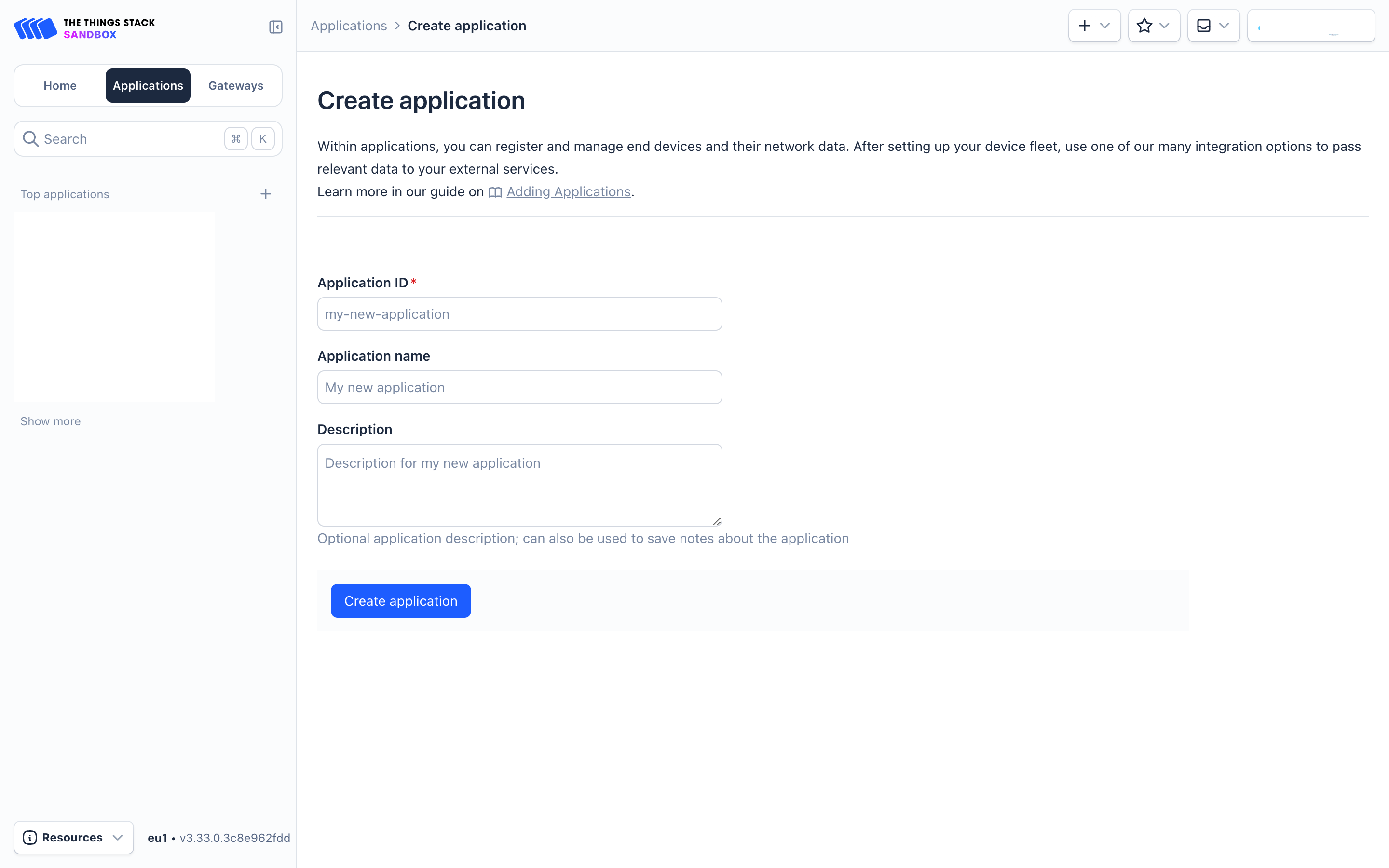
Sign up for a free account with The Things Stack Sandbox if you do not have one yet. Then, create an application as shown in the screenshots below.
Application ID: Provide a unique name to identify your application within The Things Stack, e.g., dragino-docs.
2.1.2.2 Adding manually
You can refer to the screenshots below to register your WQS-LB using The Things Stack's manual option.
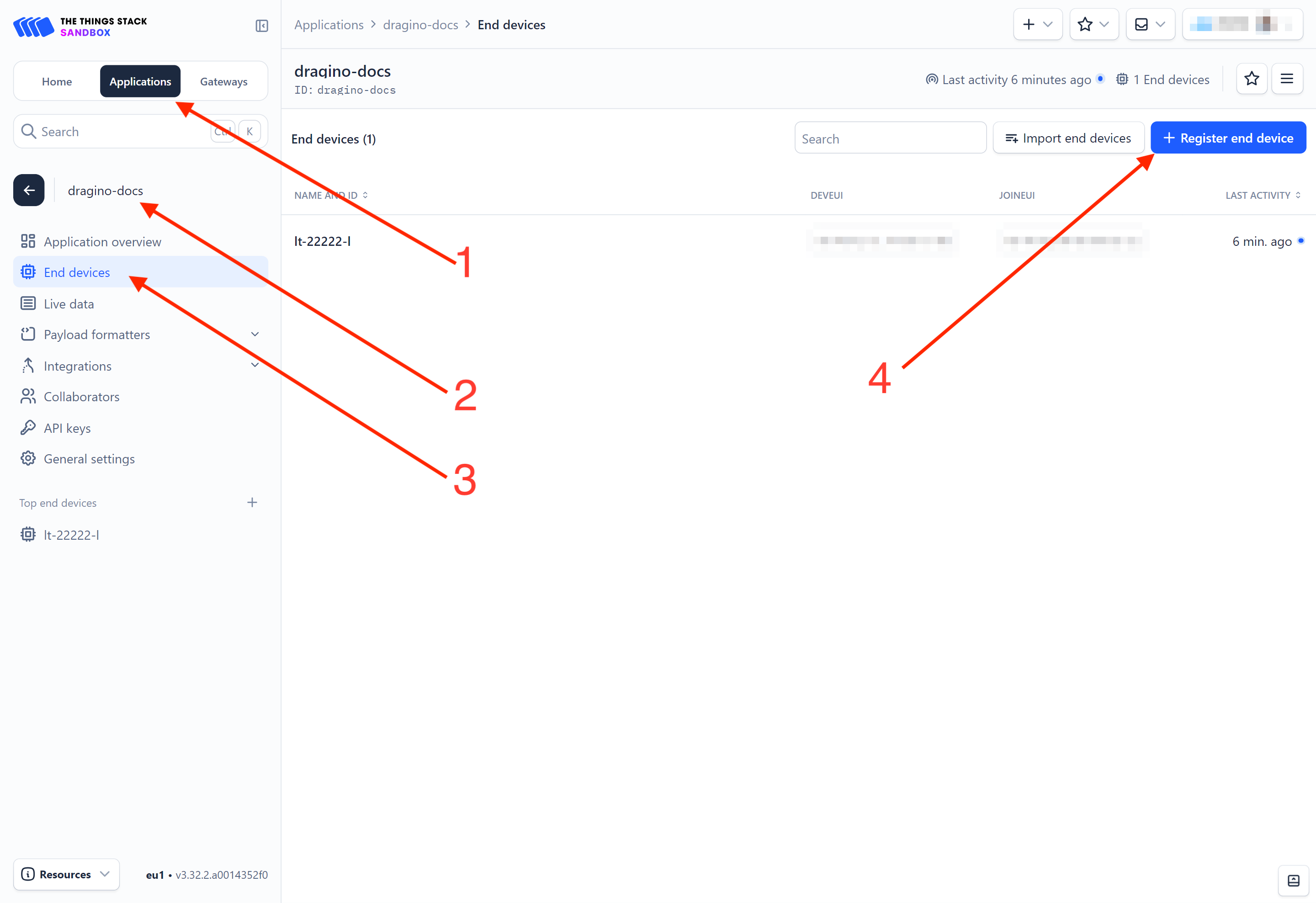
On The Things Stack console:
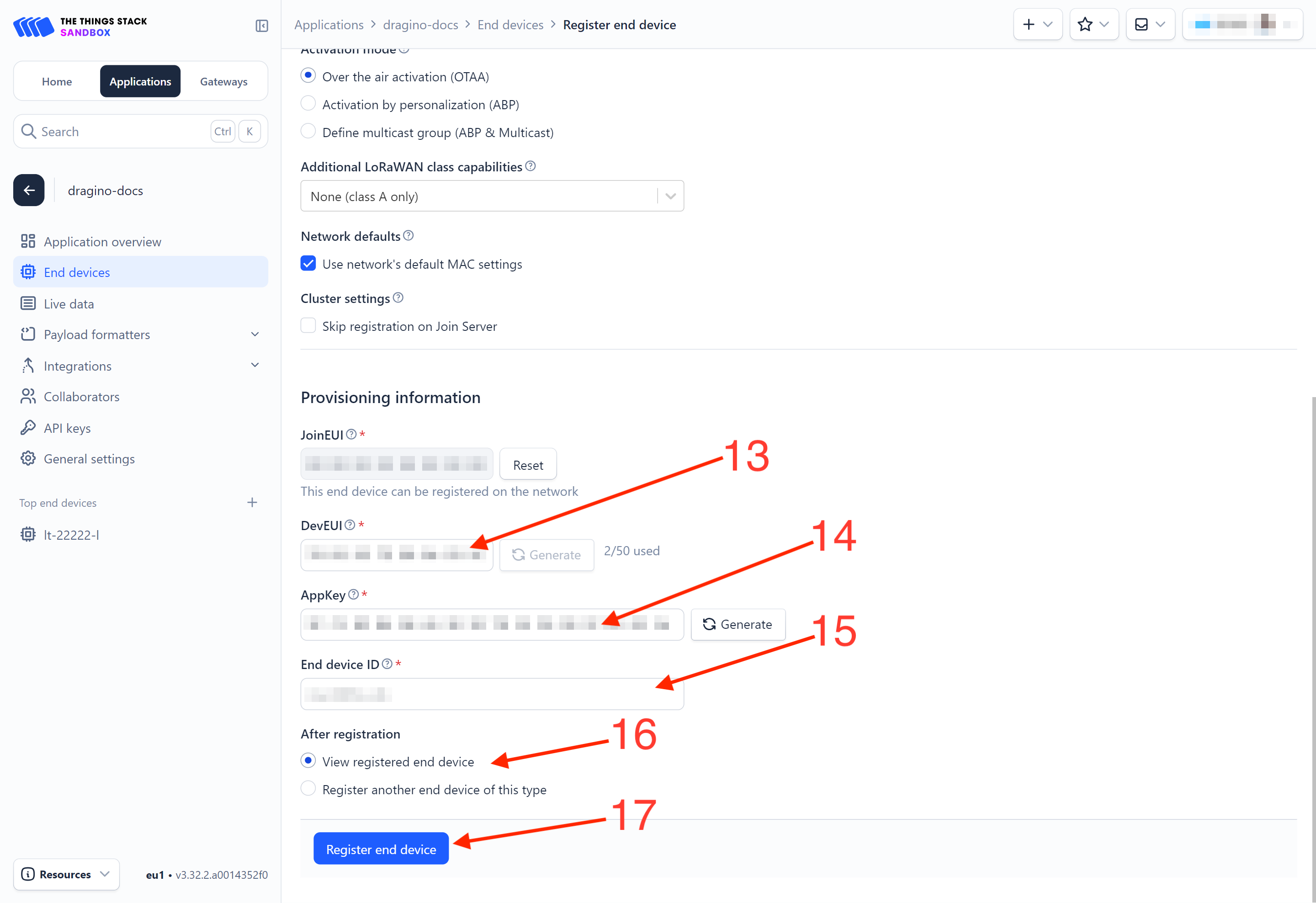
1. Click Applications.
2. Click <your application>. E.g. dragino-docs
3 Click End devices.
4. Click + Register end device button.
5. Select Enter end device specifies manually option.
6. Frequency plan: Select the frequency plan that matches your device. E.g.: Europe 863-870 MHz (SF9 for RX2 - recommended).
7. LoRaWAN version: LoRaWAN Specification 1.0.3
8. Regional Parameters version: You can't change it and it will select automatically.
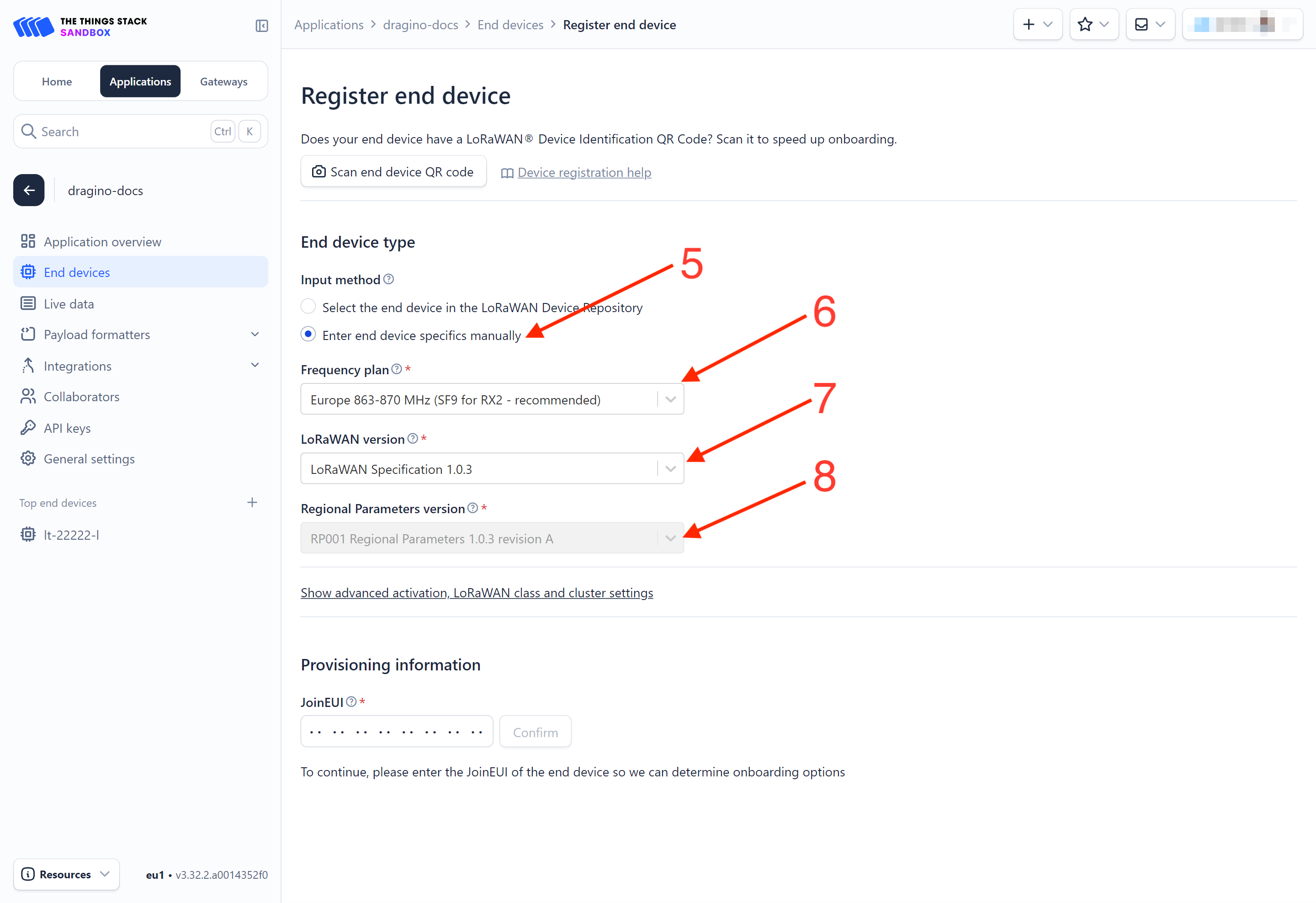
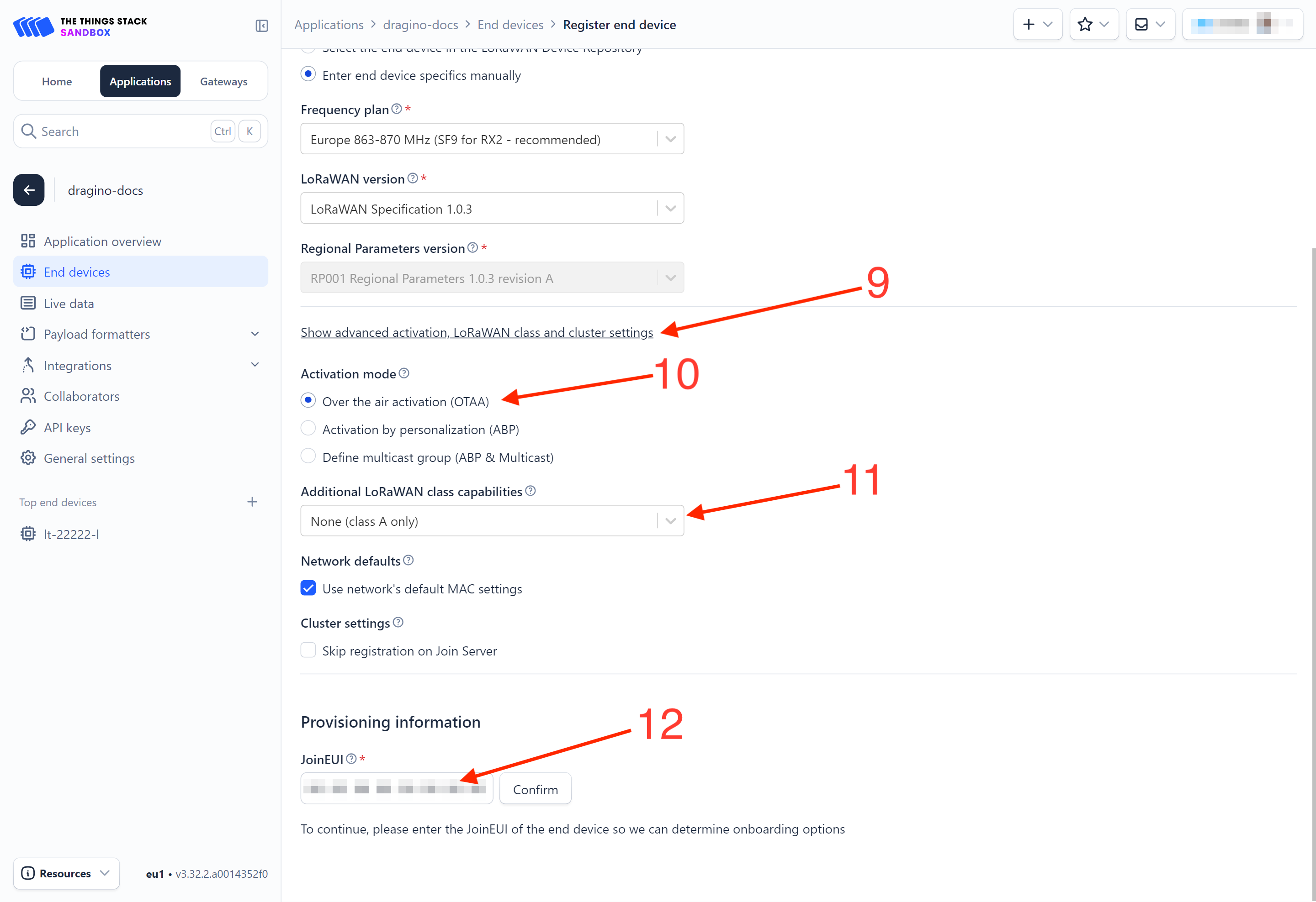
9. Click on the Show advanced activation, LoRaWAN class and cluster settings to expand the section.
10. Select Over the air activation (OTAA) option.
11. Select None (class A only).
12. JoinEUI: Enter the AppEUI of the device (see the registration information sticker) and Click the Confirm button.
13. DevEUI: Enter the DevEUI of the device (see the registration information sticker).
14. AppKey: Enter the AppKey of the device (see the registration information sticker).
15. End device ID: Enter a name for your end device to uniquely identify it within this application.
16. Click View registered end device option.
17. Click Register end device button.
You will be navigated to the Device overview page.
2.1.2.3 Power on the WQS-LB
Power on the WQS-LB. It will then join The Things Stack. Once successfully connected, the device will begin uplinking sensor data to The Things Stack, which can be viewed on the Live data panel.

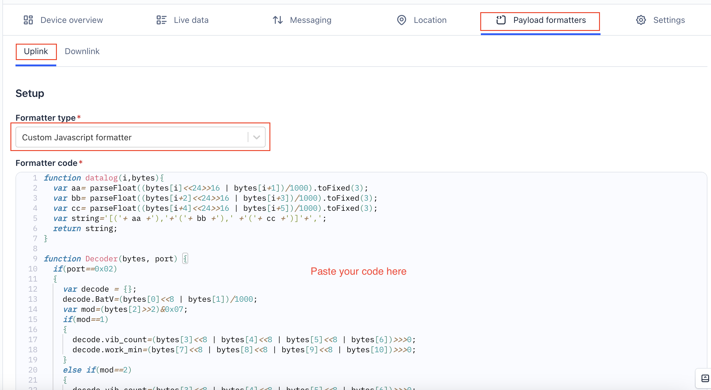
2.1.3 Uplink Decoder in The Things Stack
When the uplink payload arrives in The Things Stack, it is displayed in HEX format, which is not easy to read. You can add the WQS-LB decoder in The Things Stack for easier readability of each sensor reading.
The uplink decoder can be added to the Payload Formatters of your device in The Things Stack. Refer to the screenshot below.
1. Click Uplink tab.
2. Formatter type: Select Custom Javascript formatter.
3. Formatter code: Copy the uplink payload formatter code from our dragino-end-node-decoder GitHub repository and paste it here.
4. Finally, click on the Save changes button.
2.2 Uplink payload
Uplink payloads include two types: Valid Sensor Values and other status/control commands.
- Valid Sensor Values: Use FPort=2.
- Other status/control commands: Use FPort other than 2.
2.2.1 Uplink FPort=5, Device status
Uplink the device configuration with FPort=5. Once the WQS-LB joins the network, it will send this message to the server. After the first uplink, the WQS-LB will transmit the device status every 12 hours.
Users can also use the downlink command (0x2301) to request the WQS-LB to resend this uplink.
| Size(bytes) | 1 | 2 | 1 | 1 | 2 |
|---|---|---|---|---|---|
| Value | Sensor Model | Firmware Version | Frequency Band | Sub-band | BAT |

Example payload (FPort=5): 3C 01 00 01 00 0D C8
Sensor Model: 1 byte
For WQS-LB, this value is 0x3C.
Firmware Version: 2 bytes
0x0100, Means: v1.0.0 version.
Frequency Band: 1 byte
0x01: EU868
0x02: US915
0x03: IN865
0x04: AU915
0x05: KZ865
0x06: RU864
0x07: AS923
0x08: AS923-1
0x09: AS923-2
0x0a: AS923-3
0x0b: CN470
0x0c: EU433
0x0d: KR920
0x0e: MA869
Sub-Band: 1 byte
value 0x00 ~ 0x08 (only for CN470, AU915,US915. Others are 0x00)
BAT: 2 bytes
shows the battery voltage for WQS-LB MCU.
Ex1: 0x0DC8/1000 = 3.528 V
2.2.2 Uplink FPort=3, Datalog
Note:WQS-LB can be equipped with 3 optional sensors. The datalog is sorted in the following order.
| Size(bytes) | 2 | 2 | 2 | 2 | 2 | 2 | 4 |
|---|---|---|---|---|---|---|---|
| Value | turbidity(Options) | dissolved oxygen(Options) | ORP(Options) | ECK10(Options) | ECK1(Options) | PH(Options) | Unix TimeStamp |
Example:
The WQS-LB will uplink this payload:

048B013E03889367D39699
Where the first 10 bytes is for the first entry:
048B013E03889367D39699
dissolved oxygen=0x048B/100=11.63
ECK1=0x013E=318
PH=0x0388/100=9.04
Unix time is 0x67D39699=1741919897s=25/3/14 02:38:17
2.2.3 Uplink FPort=2, Real time sensor value
The WQS-LB will send this uplink after the Device Config uplink once it successfully joins the LoRaWAN network. It will then periodically send this uplink. The default interval is 20 minutes, but this can be changed.
The uplink uses FPort=2 and, by default, sends one uplink every 20 minutes.
The uplink length is dynamic and depends on the types of weather sensors connected. The uplink payload is composed of sensor segments, as shown below:
| Size(bytes) | 2 | 2 | 1 | 2 | 2 | 2 | 2 | 2 | 2 |
|---|---|---|---|---|---|---|---|---|---|
| Value | BAT | temperature DS18B20 | flag and Sensor Identifier | turbidity | dissolved oxygen | ORP | ECK10 | ECK1 | PH |
![]()
Payload Example (FPort=2): 0CDE 0CCC 29 01E7 00A8 03AA
The WQS-LB is connected to three sensors, PH, ORP, and turbidity.
BAT: 2 bytes
Shows the battery voltage for WQS-LB MCU.
Ex1: 0x0CDE/1000 = 3.294 V
Temperature: 2 bytes
This is the data of the external DS18B20 temperature sensor.
If the DS18B12 sensor is not connected, it will display:0CCC/10 =327.60°C
Flag and Sensor Identifier: 1 byte
The Flag and Sensor Identifier uses a hexadecimal byte, which becomes 8 digits when converted to binary.
Example:
![]()
00 indicates the interrupt identifier.
The remaining six digits represent the identifiers of the turbidity, dissolved oxygen, ORP, ECK10, ECK1, and pH sensors, in that order.
For example, 101001 means that the WQS-LB has three sensors connected: turbidity, ORP, and pH.
Sensor data: each 2 bytes, total 6 bytes
turbidity: 0x01E7/10=48.7
ORP: 0x00A8=168
pH: 0x03AA/100=9.38
2.3 Integrating data with IoT platforms
The WQS-LB sensor data can be integrated with other IoT platforms for better visualizing and analyzing the data. In this section, we will show you how to integrate sensor data from The Things Stack with some popular IoT platforms.
2.3.1 Integrate and show data on ThingsEye
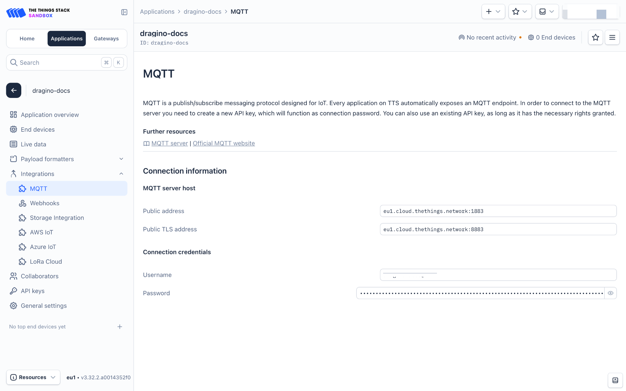
The Things Stack application supports integration with ThingsEye.io. Once integrated, ThingsEye.io acts as an MQTT client for The Things Stack MQTT broker, allowing it to subscribe to upstream traffic and publish downlink traffic.
2.3.1.1 Configuring The Things Stack
We use The Things Stack Sandbox in this example:
- In The Things Stack Sandbox, go to the Application for the WQS-LB you added.
- Select MQTT under Integrations in the left menu.
- In the Connection information section, under Connection credentials, The Things Stack displays an auto-generated username. You can use it or provide a new one.
- Click the Generate new API key button to generate a password. You can view it by clicking on the visibility toggle/eye icon. The API key works as the password.
2.3.1.2 Configuring ThingsEye.io
The ThingsEye.io IoT platform is not open for self-registration at the moment. If you are interested in testing the platform, please send your project information to admin@thingseye.io, and we will create an account for you.
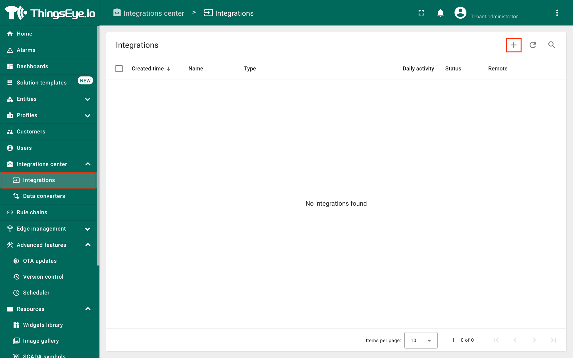
- Login to your ThingsEye.io account.
- Under the Integrations center, click Integrations.
- Click the Add integration button (the button with the + symbol).
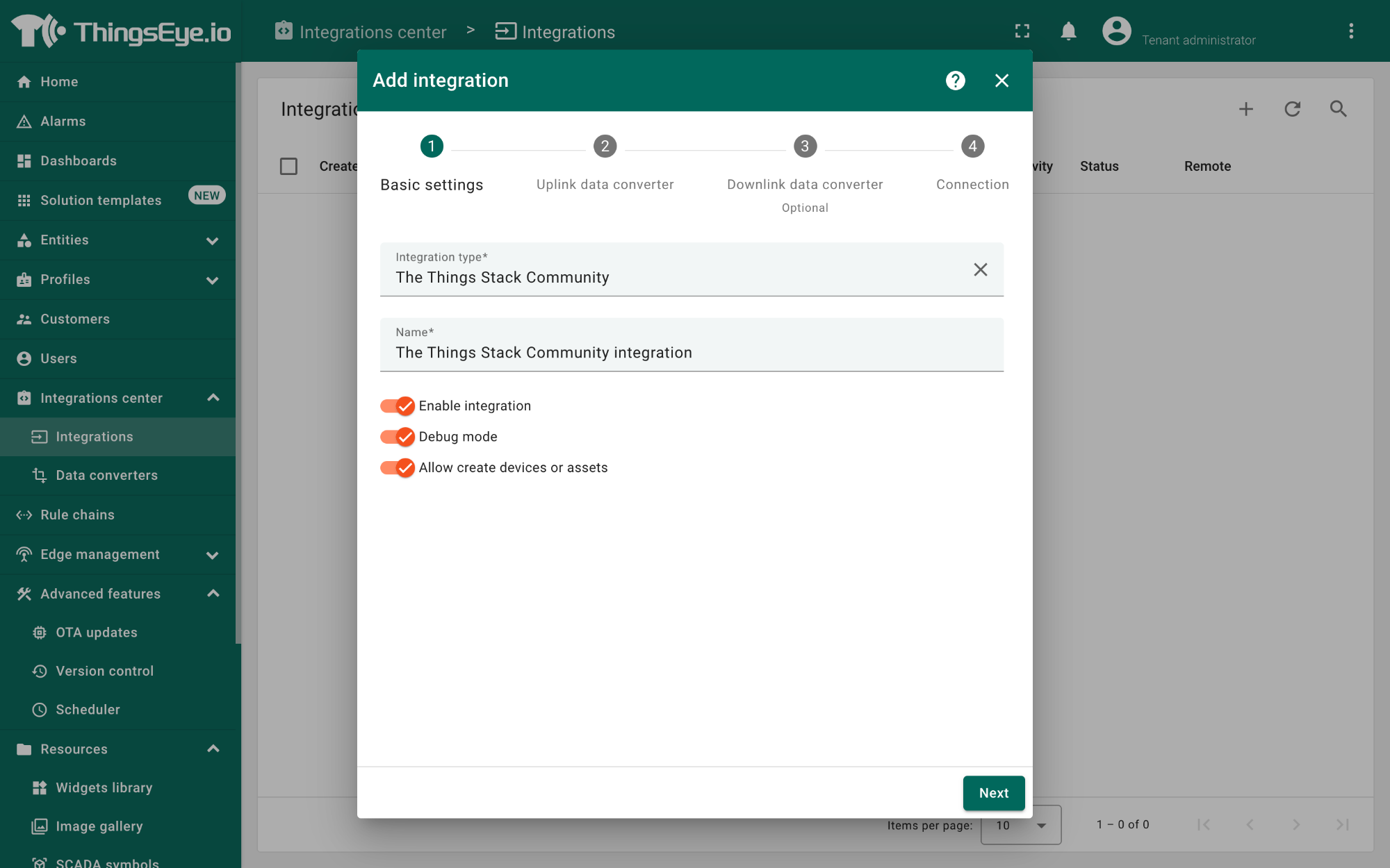
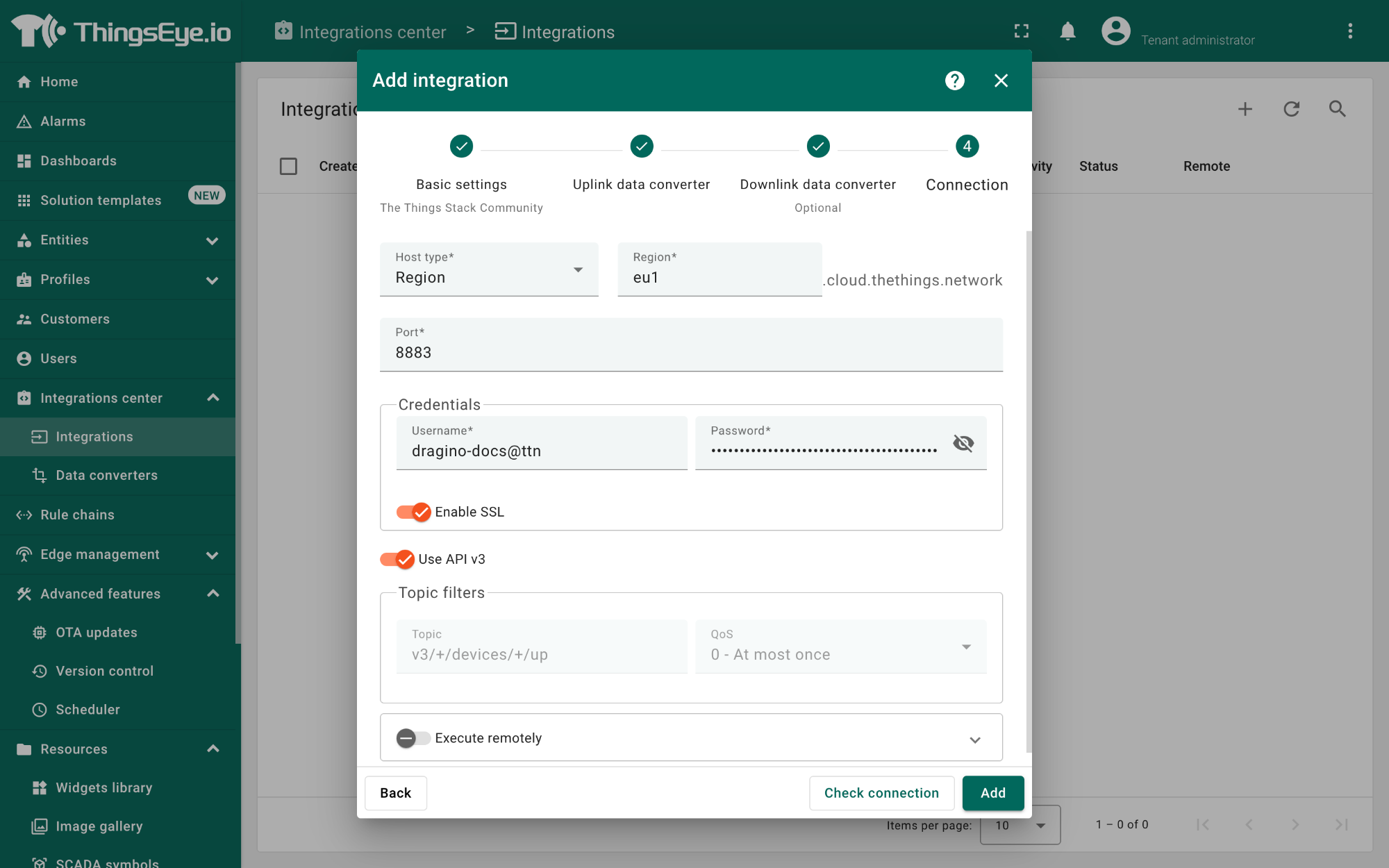
On the Add integration window, configure the following:
Basic settings:
- Select The Things Stack Community from the Integration type list.
- Enter a suitable name for your integration in the Name text box or keep the default name.
- Ensure the following options are turned on.
- Enable integration
- Debug mode
- Allow create devices or assets
- Click the Next button. you will be navigated to the Uplink data converter tab.
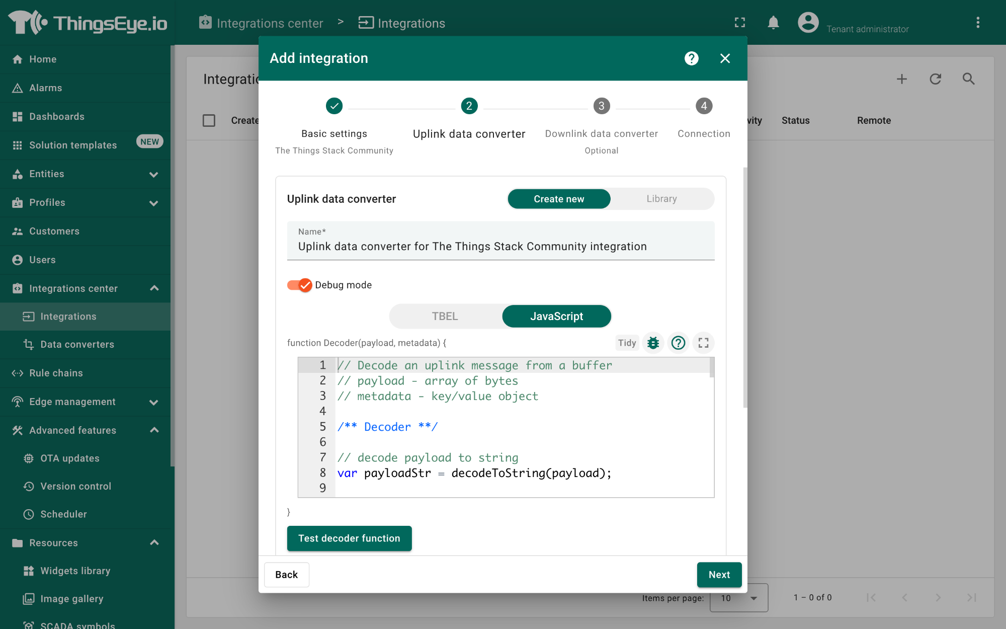
Uplink data converter:
- Click the Create new button if it is not selected by default.
- Enter a suitable name for the uplink data converter in the Name text box or keep the default name.
- Click the JavaScript button.
- Paste the uplink decoder function into the text area (first, delete the default code). The demo uplink decoder function can be found here.
- Click the Next button. You will be navigated to the Downlink data converter tab.
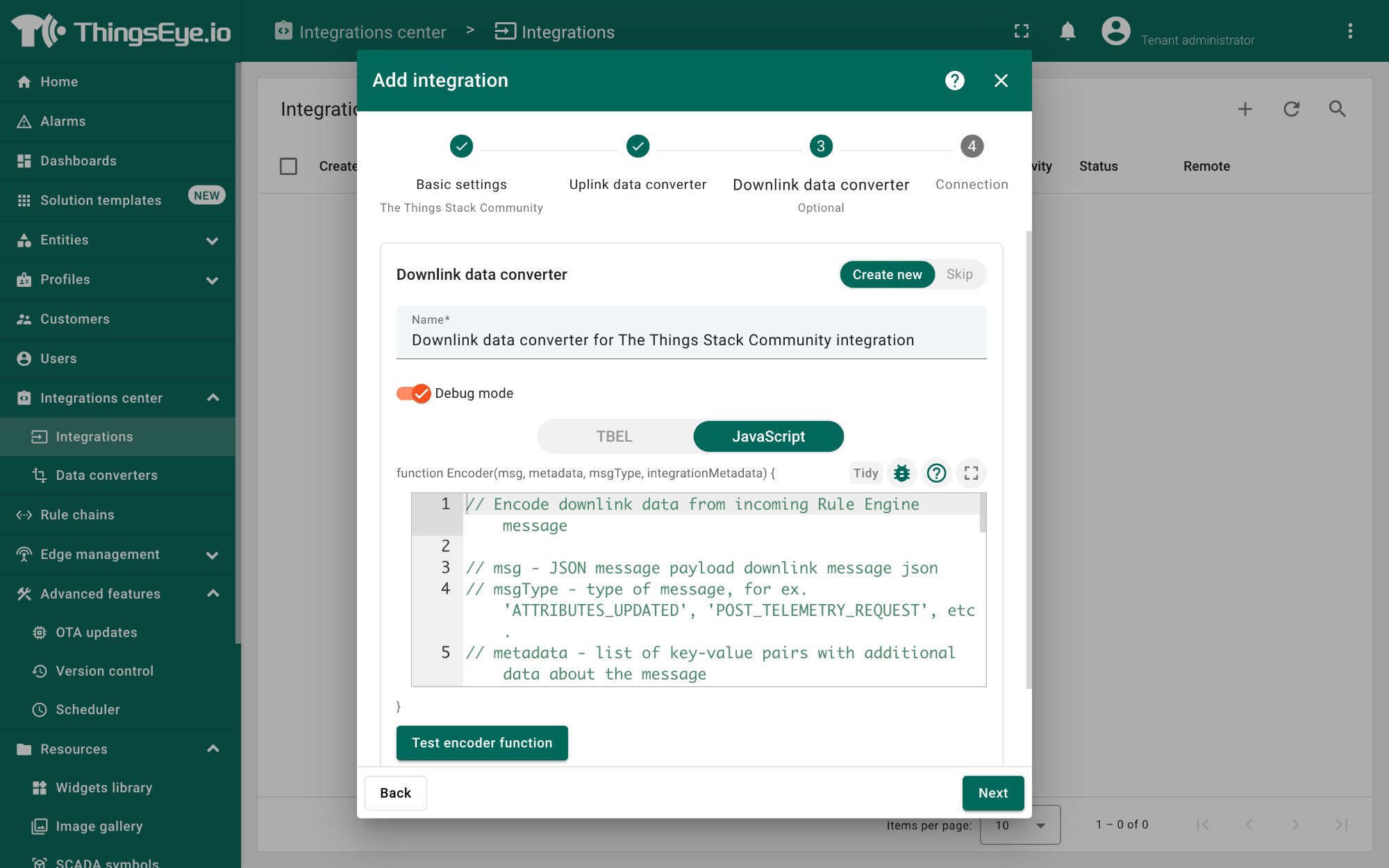
Downlink data converter (this is an optional step):
- Click the Create new button if it is not selected by default.
- Enter a suitable name for the downlink data converter in the Name text box or keep the default name.
- Click the JavaScript button.
- Paste the downlink decoder function into the text area (first, delete the default code). The demo downlink decoder function can be found here.
- Click the Next button. You will be navigated to the Connection tab.
Connection:
- Choose Region from the Host type.
- Enter the cluster of your The Things Stack in the Region textbox. You can find the cluster in the url (e.g., https://eu1.cloud.thethings.network/...).
- Enter the Username and Password of the MQTT integration in the Credentials section. The username and password can be found on the MQTT integration page of your The Things Stack account (see 3.5.1 Configuring The Things Stack).
- Click the Check connection button to test the connection. If the connection is successful, you will see the message saying Connected.
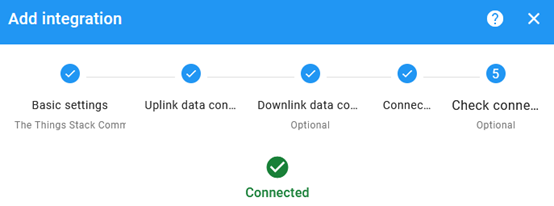
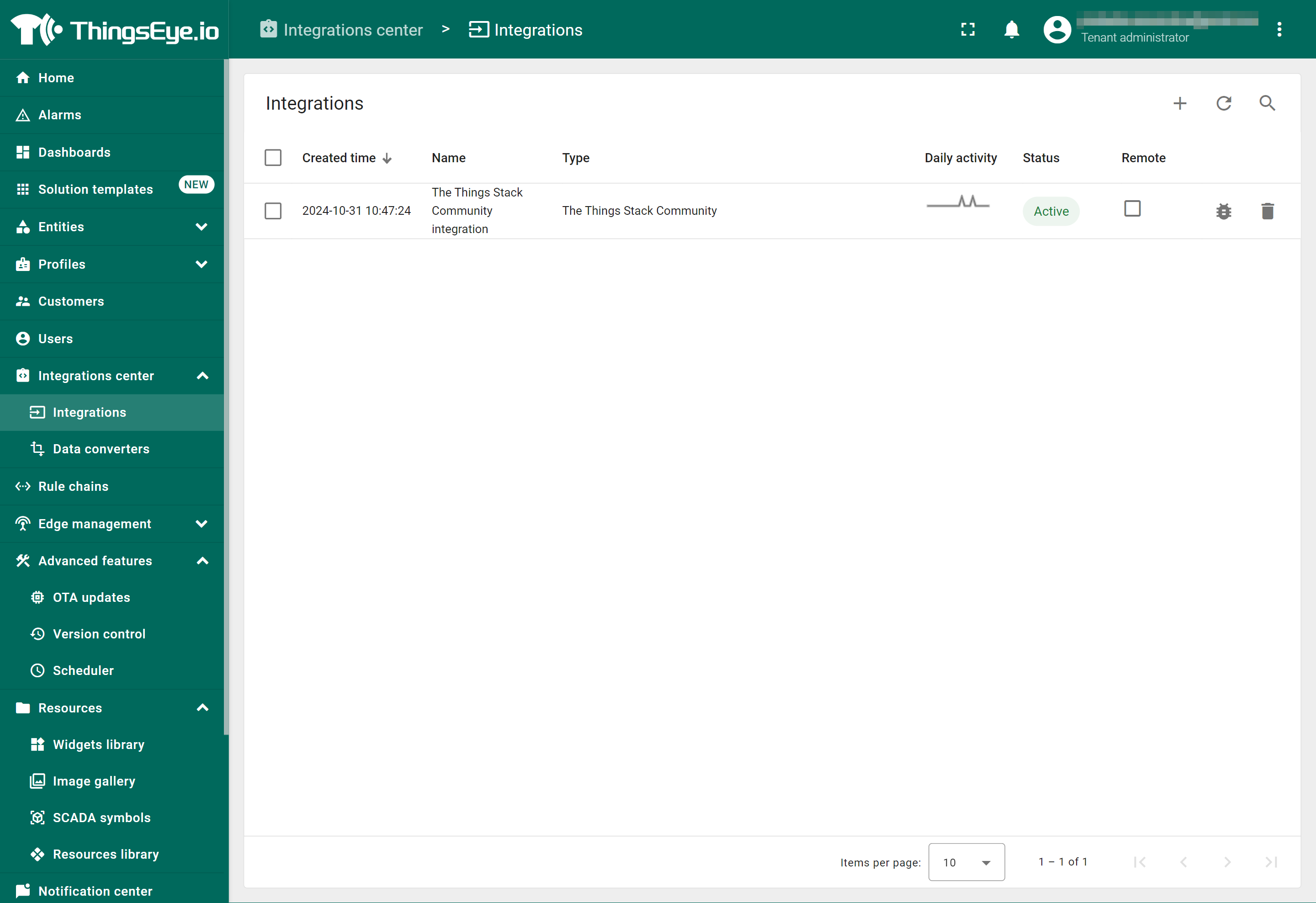
- Click the Add button.
Your integration has been added to the Integrations list and will be displayed on the Integrations page. Check whether the status is shown as Active. If not, review your configuration settings and correct any errors.
2.3.1.3 Viewing integration details
Click on your integration from the list. The Integration details window will appear with the Details tab selected. The Details tab shows all the settings you have provided for this integration.
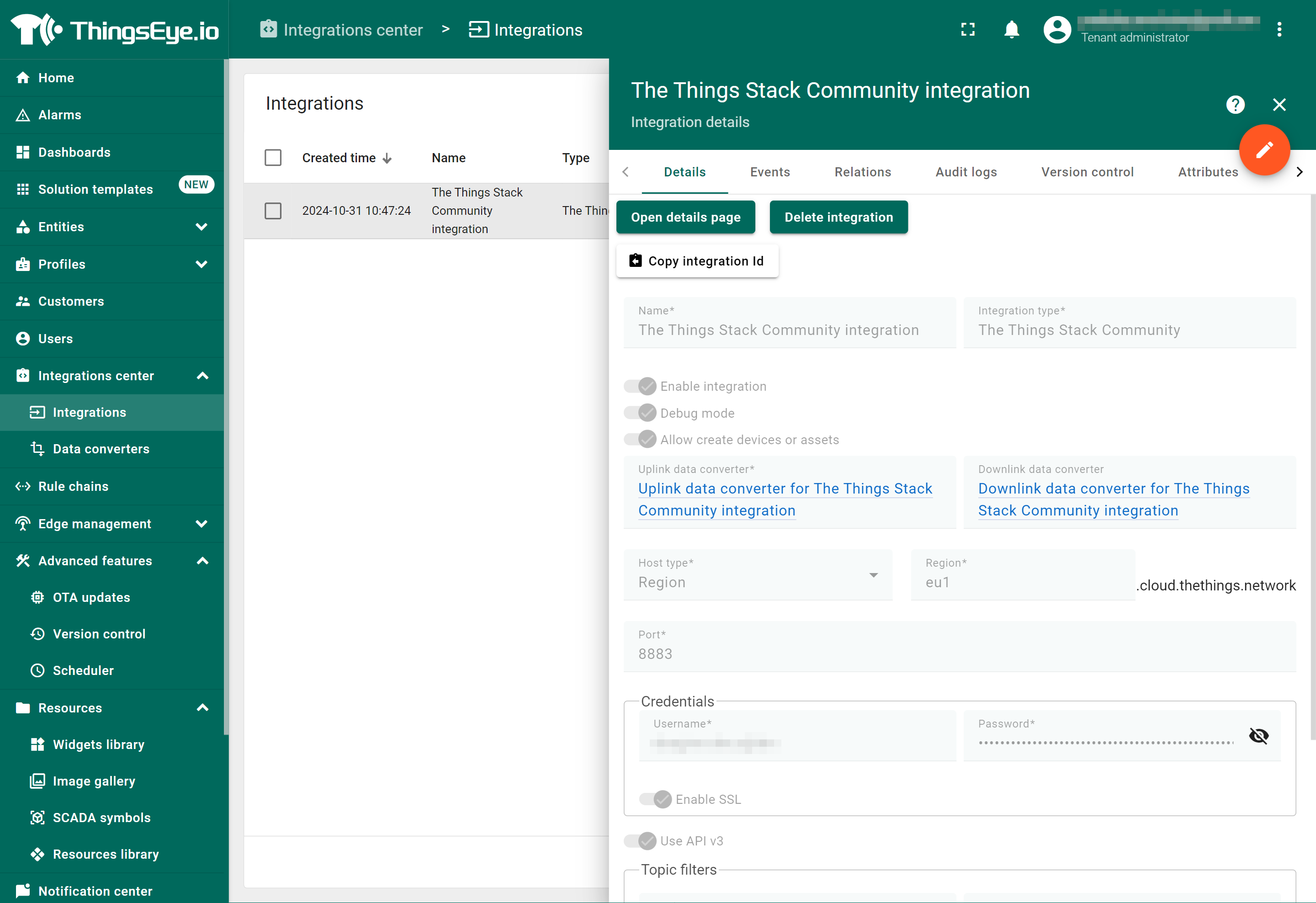
If you want to edit the settings you have provided, click on the Toggle edit mode button. Once you have done click on the Apply changes button.
2.3.1.4 Viewing events
The Events tab displays all the uplink messages from the WQS-LB.
- Select Debug from the Event type dropdown.
- Select the time frame from the time window.
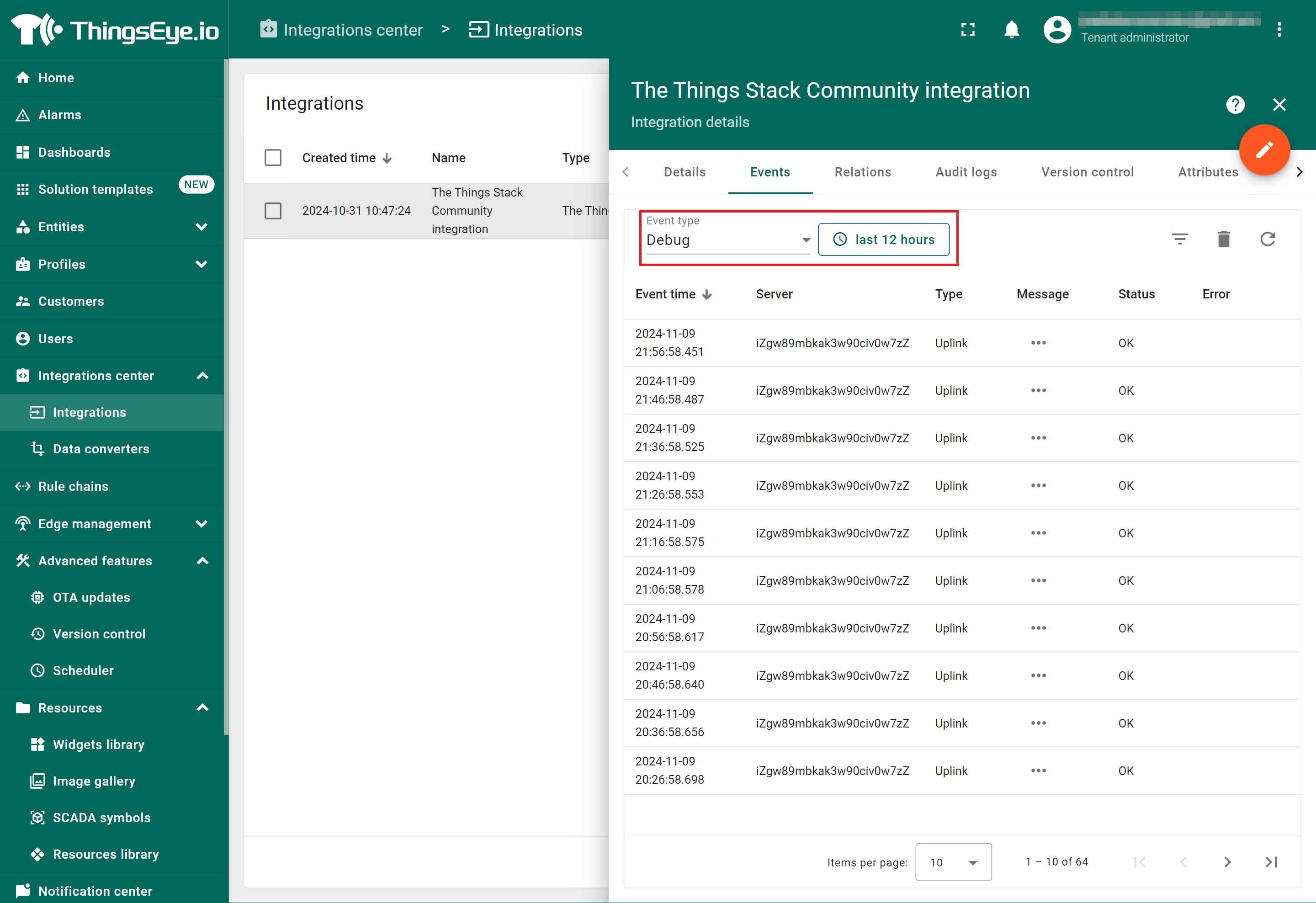
- To view the JSON payload of a message, click on the three dots (...) in the Message column of the desired message.

2.3.1.5 Deleting an integration
If you want to delete an integration, click the Delete integration button on the Integrations page.
2.3.1.6 Creating a dashboard
The following image shows a dashboard created using ThingsEye to display sensor data on widgets, allowing users to analyze and visualize the data.

2.3.2 Integrate and show data on TagoIO
TagoIO is a scalable IoT platform that allows easily build scalable IoT solutions. The Things Stack application supports integration with TagoIO using webhooks.
- Ensure that WQS-LB is properly connected to The Things Stack.
- Then configure your The Things Stack application to forward data to TagoIO by adding an integration with webhooks.
- In The Things Stack console, navigate to Applications → <your application> → Integrations → Webhooks → + Add webhook.
Step 1: Be sure that your device is programmed and properly connected to the LoRaWAN network.
Step 2: Configure your Application to forward data to Datacake you will need to add integration. Go to TTN V3 Console --> Applications --> Integrations --> Add Integrations.

In the Setup webhook for TagoIO page:
- Webhook ID - enter a name to identify your webhook.
- Authorization: Paste the authorization code copied from the TagoIO.
- Click Create TagoIO webhook button.

Authorization:

In TagoIO console (https://admin.tago.io//) , add WQS-LB:

3. Configure the WQS-LB using AT commands or LoRaWAN downlinks
You can configure the WQS-LB using AT Commands or LoRaWAN Downlinks.
- AT Commands: See FAQ.
- LoRaWAN Downlink instruction for different platforms: Use Note for Server (IoT LoRaWAN Server)
There are two types of commands to configure the WQS-LB:
1. General Commands - They are the same for all Dragino devices that support the DLWS-005 LoRaWAN Stack (Note**). These commands can be found on the wiki: End Device Downlink Command.
These commands are used to configure:
- General system settings, such as the uplink interval.
- LoRaWAN protocol and radio-related settings.
Note: Please refer to the earlier user manual if you don’t have firmware version 1.8.0.
2. Commands Specifically Designed for the WQS-LB
These commands are valid only for the WQS-LB, as shown below:
3.1 Set transmit interval time
Feature: Set the uplink interval.
AT command:
| Command | AT+TDC |
| Parameters | time : uplink interval in milliseconds |
| Get | AT+TDC=? |
| Response | time in milliseconds OK |
| Set | AT+TDC=<time> |
| Response | OK |
| Example | AT+TDC=60000 Set uplink interval to 60 seconds |
Downlink command:
| Prefix | 0x01 |
| Parameters | time : uplink interval in seconds, 3 bytes in hexadecimal. |
| Payload | <prefix><time> |
| Example | 0100003C Set uplink interval to 60 seconds |
3.2 Set interrupt mode
Feature: Set the interrupt mode.
AT command:
| Command | AT+INTMOD |
| Parameters | interrupt_mode : 0 : Disable interrupt |
| Get | AT+INTMOD=? |
| Response | interrupt mode OK |
| Set | AT+INTMOD=<interrupt_mode> |
| Response | OK |
| Example | AT+INTMOD=2 Set the interrupt mode to 'trigger by falling edge' |
3.3 Set power output duration
Feature: Set power output duration
AT Command:
| Command | AT+5VT |
| Parameters | time : power output duration in milliseconds |
| Get | AT+5VT=? |
| Response | time OK |
| Set | AT+5VT=<time> |
| Response | OK |
| Example | AT+5VT=1000 Close after a delay of 1000 milliseconds |
Downlink Command:
| Prefix | 0x07 |
| Parameters | time : power output duration in seconds, 2 bytes in hexadecimal |
| Payload | <prefix><time> |
| Example | 070000 Set to 0 0701F4 Set to 500 seconds |
3.4 Sensor Calibration Commands
Specific operation steps
1. Put the sensor into the corresponding calibration liquid.
2. Restart the device.
3. Send calibration instructions.
4. Receive the byte corresponding to return.
5. Received OK is a successful calibration.
| Command Example | Function | Response |
|---|---|---|
| AT+CALPH=xx | Parameter 4 6 9 downlink: 0xFB XX | 4:10 06 00 22 ff ff 2b 31 6:10 06 00 21 ff ff db 31 9:10 06 00 20 ff ff 8a f1 |
| AT+CALORP=xx | Parameter 86 256 downlink:0xFC XX XX | 86:13 06 00 24 07 dc c9 1a 256:13 06 00 25 07 37 d8 95 |
| AT+CALEC=xx | Parameter 1 10 downlink:0xFD XX | 1:12 01 00 26 00 02 A2 A0 10:11 10 00 26 00 02 A2 93 |
| AT+CALNTU=xx | Parameters 0 2 4 6 8 10 downlink: 0xFE XX | 0:15 06 00 5E 00 01 2A CC 2:15 06 00 5E 00 02 6A CD 4:15 06 00 5E 00 03 AB 0D 6:15 06 00 5E 00 04 EA CF 8:15 06 00 5E 00 05 2B 0F 10:15 06 00 5E 00 06 6B 0E |
4. Water Quality Sensors
4.1 pH Sensor
The PH01 is a device used to measure the pH value (hydrogen ion concentration index), indicating the acidity or alkalinity of a solution. It features an integrated design, making it lighter, simpler in structure, and more convenient to use. The device has an IP68 waterproof rating. The reference electrode uses a double salt bridge design, providing enhanced resistance to pollution. This product is ideal for applications in industrial sewage, domestic sewage, agriculture, aquaculture, and other settings involving non-corrosive weak acid and weak alkali environments.
4.1.1 Features
- pH measurement range: 0–14 pH, with a resolution of 0.01 pH.
- One-piece design with a light, simple structure, making it easy to use.
- The reference electrode features a double salt bridge design, offering stronger anti-pollution resistance and an IP68 waterproof rating.
- The device uses a wide voltage power supply, ranging from DC 7V to 30V.
4.1.2 Specifications
- Power supply: DC 7–30V
- Power consumption: ≤ 0.5W
- Communication interface: RS485, standard MODBUS-RTU protocol; communication baud rate: default 9600
- pH measurement range: 0–14.00 pH; resolution: 0.01 pH
- pH measurement error: ± 0.15 pH
- Repeatability error: ± 0.02 pH
- Working environment:
- Ambient Temperature: 0–60°C
- Relative Humidity: <85% RH(Specifically refers to the cable male and female)
- Waterproof rating: IP68
- Pressure resistance: 0.6 MPa
4.1.3 Dimensions

4.1.4 Installation
Do not power on while connecting the cables. Double-check the wiring before powering it on.
Installation diagrams are shown below for your reference (see submerged installation and pipeline installation):
Submerged installation:
The lead wire of the equipment passes through the waterproof pipe, and the 3/4-inch thread on the top of the device is connected to the 3/4-inch thread of the waterproof pipe using thread seal tape. Ensure that the top of the equipment and the device wire are not exposed to water.

Pipeline installation:
Connect the device to the pipeline using the 3/4-inch thread.

Sampling:
Take representative water samples according to the sampling requirements. If it is inconvenient to take samples, you can also place the electrode into the solution to be tested and read the output data. After some time, remove the electrode and clean it.
Measure the pH of the water sample:
First, rinse the electrode with distilled water, then with the water sample. Immerse the electrode in the sample, gently shake the test cup or stir to accelerate the electrode’s stabilization. Allow it to stand and record the pH value once the reading stabilizes.
4.1.5 Maintenance
- General Maintenance:
The equipment generally does not require daily maintenance. However, if an obvious fault occurs, please do not attempt to open or repair it yourself. Contact us as soon as possible! - Soaking Solution:
There is an appropriate amount of soaking solution in the protective bottle at the front end of the electrode. The electrode head is soaked in it to keep the glass bulb and liquid junction active.
When measuring, loosen the bottle cap, pull out the electrode, and rinse it with pure water before use. Preparation of Electrode Soaking Solution:
- Take a packet of pH 4.00 buffer, dissolve it in 250 ml of pure water, and soak it in 3M potassium chloride solution.
- To prepare the solution: dissolve 25 grams of analytical-grade potassium chloride in 100 ml of pure water.
- Handling of the Electrode:
The glass bulb at the front end of the electrode should not come into contact with hard objects. Any damage or scratches will make the electrode ineffective. - Before Measurement:
Shake off any bubbles in the electrode's glass bulb, as they will affect the measurement.
While measuring, the electrode should be stirred in the sample solution, then allowed to rest to accelerate the response. - Cleaning:
The electrode should be cleaned with deionized water before and after each measurement to ensure accuracy. Passivation of the pH Electrode:
After long-term use, the pH electrode may become passivated, which is characterized by a decrease in sensitivity, slow response, and inaccurate readings.- In this case, soak the bulb at the bottom of the electrode in 0.1M dilute hydrochloric acid for 24 hours (0.1M dilute hydrochloric acid preparation: dilute 9 ml of hydrochloric acid to 1000 ml with distilled water), and then soak it in 3.3M potassium chloride solution for 24 hours.
- If the electrode is seriously passivated and soaking in 0.1M hydrochloric acid has no effect, the pH electrode bulb can be soaked in 4% HF (hydrofluoric acid) for 3-5 seconds, washed with pure water, and then soaked in 3.3M potassium chloride solution for 24 hours to restore its performance.
- Contamination and Blockage:
Contamination of the glass bulb or blockage of the liquid junction can also cause electrode passivation. In this case, clean the electrode with an appropriate solution based on the nature of the contaminant. - Calibration:
The equipment should be calibrated before each use.
For long-term use, it is recommended to calibrate every 3 months. The calibration frequency should be adjusted based on different application conditions (e.g., degree of dirt, deposition of chemical substances). - Electrode Replacement:
After prolonged use, replace the electrodes in a timely manner.
4.1.6 Calibration
This device uses a three-point calibration, requiring the preparation of three known pH standard solutions.
The steps are as follows:
- Wash the electrode with distilled water and place it in the 9.18 standard buffer solution. Once the data stabilizes, enter the following calibration command to complete the 9.18 calibration:
AT+CALPH=9
Downlink: 0xFB 09 - Wash the electrode with distilled water and place it in the 6.86 standard buffer solution. Once the data stabilizes, enter the following calibration command to complete the 6.86 calibration:
AT+CALPH=6
Downlink: 0xFB 06 - Wash the electrode with distilled water and place it in the 4.01 standard buffer solution. Once the data stabilizes, enter the following calibration command to complete the 4.00 calibration:
AT+CALPH=4
Downlink: 0xFB 04
4.2 EC Sensor
EC K1/K10 is a device used for measuring the conductivity of solutions. It adopts an integrated design, making it lighter, simpler in structure, and more convenient to use.
The waterproof rating is IP68, and it can be widely used for continuous monitoring of the conductivity of aqueous solutions, such as those in cross-section water quality, aquaculture, sewage treatment, environmental protection, pharmaceuticals, food, and tap water.
4.2.1 Features
- Conductivity measurement range: 0-2000 µS/cm; 10-20000 µS/cm.
- Integrated design with a light and simple structure, easy to use.
- Waterproof grade: IP68.
- Salinity and TDS conversion function.
- RS485 communication interface: Modbus RTU protocol, easily connected to a computer for monitoring and communication.
- Modbus communication address can be set, and baud rate can be modified.
- Wide voltage power supply: DC 7-30V is supported.
4.2.2 Specifications
- Power supply: DC 7-30V
- Power consumption: ≤ 0.5W
- Communication interface: RS485; standard MODBUS-RTU protocol; communication baud rate: default 9600
- Conductivity measurement range:
- K=1: 0-2000 μS/cm; resolution: 1 μS/cm
- K=10: 10-20000 μS/cm; resolution: 10 μS/cm
- Conductivity measurement error: ±1% FS
- Working environment:
- Ambient Temperature: 0–60°C
- Relative Humidity: <85% RH(Specifically refers to the cable male and female)
- Waterproof grade: IP68
- Pressure resistance: 0.6 MPa
4.2.3 Dimensions
4.2.4 Installation
Selection of matching electrode constant:

Electrode Installation Types
- A: Side wall installation
- B: Top flange installation
- C: Pipeline bend installation
- D: Another pipeline bend installation
- E: Flow-through installation
- F: Submerged installation

Several Common Installation Methods for Electrodes
When installing the sensor on-site, you should strictly follow the correct installation method shown in the following picture. Incorrect installation methods can cause data deviation.
A. Several common incorrect installation methods:

Error cause: The electrode joint is too long, and the extension part is too short. This causes the sensor to form a dead cavity, resulting in measurement errors.

Error cause: Measurement errors or instability may occur if the water flow cannot fill the pipe or if air accumulates at high altitudes.
B. Correct installation method

4.2.5 Maintenance
- The equipment itself generally does not require daily maintenance. When an obvious fault occurs, please do not attempt to open or repair it yourself; instead, contact us as soon as possible.
- If the electrode is not used for an extended period, it can generally be stored in a dry place. However, it must be placed (or stored) in distilled water for several hours before use to activate the electrode. Electrodes that are frequently used can be stored in distilled water.
- Cleaning of conductivity electrodes: Organic stains on the electrode can be cleaned with warm water containing detergent or alcohol. Calcium and magnesium precipitates are best cleaned with 10% citric acid. The electrode plate or pole should only be cleaned using chemical methods or by shaking in water. Wiping the electrode plate will damage the coating (platinum black) on the electrode surface.
- The equipment should be calibrated before each use. For long-term use, it is recommended to calibrate it every 3 months. The calibration frequency should be adjusted appropriately based on different application conditions (e.g., degree of dirt in the application, deposition of chemical substances, etc.).
4.2.6 Calibration
This device uses one-point calibration, and you need to prepare a known E standard solution. When the range is K=1 (1–2000), use a 1413 µS/cm standard solution. When the range is K=10 (10–20000), use a 12.88 mS/cm standard solution.
The steps are as follows:
- Put the electrode in distilled water to clean it. When the range is 1–2000, use the 1413 µS/cm standard solution. After the data is stable, enter the following calibration command:
AT+CALEC=1
Downlink: 0xFD 01 - Put the electrode in distilled water to clean it. When the range is 10–20000, use the 12.88 mS/cm standard solution. After the data is stable, enter the following calibration command:
AT+CALEC=10
Downlink: 0xFD 10
4.3 ORP Sensor
The ORP01 is a device for measuring the redox potential of a solution. It features a high-purity platinum ORP composite electrode with strong resistance to acids and alkalis, excellent antioxidant capacity, high measurement accuracy, fast response, and good stability.
The electrode automatically compensates for temperature, making it suitable for online monitoring of the redox potential in cyanide-containing and chromium-containing wastewater.
4.3.1 Features
- ORP Measurement Range: -1999~1999 mV, resolution: 1 mV.
- Applicable Electrode Temperature: 0~80°C.
- Electrode Material: Made of high-purity platinum, offering strong resistance to acids and alkalis, excellent antioxidant capacity, high measurement accuracy, fast response, and good stability.
- RS485 Communication Interface: The ModBus-RTU communication protocol enables easy connection to a computer for monitoring and communication.
- ModBus Features: The communication address is configurable, and the baud rate can be modified.
- Power Supply: Operates with a wide voltage range, DC 7~30 V.
4.3.2 Specifications
- Measuring Range: -1999~1999 mV
- Resolution: 1 mV
- Output Signal: RS485
- Measurement Error: ±3 mV
- Stability: ≤2 mV/24 hours
- Working environment:
- Ambient Temperature: 0–60°C
- Relative Humidity: <85% RH(Specifically refers to the cable male and female)
- Waterproof Grade: IP68
- Pressure Resistance: 0.6 MPa
4.3.3 Dimensions
4.3.4 Installation Note
Do not power on while connecting the cables. Double-check the wiring before powering it on.
Installation diagrams are shown below for your reference (see submerged installation and pipeline installation):
Submerged installation:
The equipment's lead wire passes through a waterproof pipe, and the 3/4-inch thread on the top of the equipment is connected to the 3/4-inch thread of the waterproof pipe using raw tape. Ensure that both the top of the equipment and the equipment wire remain dry and are not submerged.
Pipeline installation:
Connect the equipment to the pipeline using the 3/4-inch thread.
4.3.5 Maintenance
- The equipment itself generally does not require daily maintenance. If a significant fault occurs, do not attempt to open or repair it yourself. Please contact us as soon as possible.
- ORP electrodes typically do not require calibration and can be used directly. However, if there are concerns about the electrode's quality or test results, the electrode potential can be checked using an ORP standard solution. This will help determine whether the electrode meets measurement requirements. If necessary, recalibrate or replace the electrode. The frequency of electrode calibration or inspection depends on the application conditions, such as the level of dirt or the deposition of chemical substances.
- The protective bottle at the front end of the electrode contains an appropriate soaking solution to ensure the activation of the platinum sheet and the liquid junction. Before measuring, loosen the bottle cap, remove the electrode, and rinse it with pure water.
- Preparation of Electrode Soaking Solution: Dissolve 25 grams of analytical-grade potassium chloride in 100 ml of pure water to prepare a 3.3M potassium chloride solution.
- Before measuring, ensure there are no air bubbles in the electrode's glass bulb, as they can affect measurements. Shake off any bubbles, stir the electrode in the solution being measured, and then let it sit to accelerate the response.
- Clean the electrode with deionized water before and after each measurement to maintain accuracy.
- After long-term use, the ORP electrode may become passivated, resulting in reduced sensitivity, slower response, or inaccurate readings. To restore performance, soak the platinum sheet at the bottom of the electrode in 0.1M dilute hydrochloric acid for 24 hours (prepare by diluting 9 ml of hydrochloric acid with distilled water to 1000 ml). Then, soak the electrode in 3.3M potassium chloride solution for another 24 hours.
- Contamination or blockage of the liquid junction can also cause passivation. Clean the electrode using an appropriate solution based on the type of contaminant. If the platinum surface is severely contaminated with an oxide film, apply toothpaste to the surface and gently scrub to restore its luster.
- Calibrate the equipment before each use. For long-term use, calibration is recommended every three months, with the frequency adjusted based on application conditions (e.g., dirt levels or chemical deposition). Replace aging electrodes promptly.
4.3.6 Calibration
The OPR01 uses two-point calibration. To perform the calibration, you need two known ORP standard solutions.
Clean the electrode with distilled water. Place it in an 86 mV standard buffer, wait for the data to stabilize, and then enter the following calibration command to complete the 86 mV point calibration:
AT+CALORP=86
downlink: 0xFC 00 56
Clean the electrode with distilled water again. Place it in a 256 mV standard buffer, wait for the data to stabilize, and then enter the following calibration command to complete the 256 mV point calibration:
AT+CALORP=256
downlink: 0xFC 01 00
4.4 Dissolved Oxygen Sensor
The fluorescence dissolved oxygen sensor is a newly developed online digital sensor, utilizing imported components, advanced production technology, and surface-mounting technology.
It features an IP68 waterproof rating, and its cable is seawater-proof. The sensor can be directly submerged in water without a protective tube, ensuring long-term stability, reliability, and accuracy.
The fluorescence dissolved oxygen sensor operates based on the principle of quenching active fluorescence by specific substances in physics.
A blue light emitted by a light-emitting diode (LED) shines on the fluorescent material located on the inner surface of the fluorescent cap.
This fluorescent material is excited and emits red light.
By detecting the phase difference between the red light and the blue light and comparing it with the internal calibration value, the concentration of oxygen molecules is calculated. The final value is automatically compensated for temperature and air pressure.
4.4.1 Features
- Compact size, low power consumption, and easy portability.
- Achieves low cost, low price, and high performance.
- High integration, long lifespan, and high reliability.
- Supports up to four isolations, resistant to complex interference conditions on-site, with a waterproof rating of IP68.
- The electrode uses a high-quality, low-noise cable, enabling the signal output length to exceed 20 meters.
4.4.2 Specifications
- Measuring range: 0–20 mg/L, 0–50℃
- Accuracy: ±3%, ±0.5℃
- Resolution: 0.01 mg/L, 0.01℃
- Maximum operating pressure: 6 bar
- Output signal:
- A: 4–20 mA (current loop)
- B: RS485 (standard Modbus-RTU protocol, default device address: 01)
- Power supply voltage: 5–24 V DC
- Working environment:
- Ambient Temperature: 0–60°C
- Relative Humidity: <85% RH(Specifically refers to the cable male and female)
- Power consumption: ≤0.5 W
4.4.3 Dimensions

4.4.4 Instructions for use and maintenance
- Sampling: Take representative water samples following the sampling requirements.
Determine dissolved oxygen in water samples:
- Rinse the electrode three times with distilled water, then rinse it three times with the water sample.
- Immerse the electrode in the sample, carefully shake the test cup or stir the solution to accelerate electrode stabilization.
- Let the sample stand and record the dissolved oxygen when the reading becomes stable.
Alternative measurement method:
- If taking samples is inconvenient, place the electrode directly in the measured solution.
- Wait for the reading to stabilize, record the output data, and remove the electrode after a period of time.
- Clean the electrode afterward.
Post-measurement care:
- After measuring the sample, rinse the electrode three times with distilled water.
- Store the electrode upright in the protective solution.
Note: When measuring multiple samples, clean the electrode before proceeding to the next sample to avoid contamination and ensure accurate results.
Additional Tip: If the water conditions are complex and precise data is required, clean the sensor probe frequently.
4.4.5 Precautions
- To ensure accurate measurements on the pipeline, avoid bubbles in the measuring cells, as they can cause data inaccuracies.
- Verify that the packaging is intact and that the product model matches the selected model.
- Do not connect the wires while the power is on. Turn on the power only after completing and verifying the wiring.
- Avoid altering components or wires that were soldered at the factory when using the product.
- The sensor is a precision device. Do not disassemble it, or allow the sensor surface to come into contact with sharp objects or corrosive liquids, to prevent damage.
4.5 Turbidity Sensor
The turbidity sensor is a newly developed online digital sensor, designed with imported components, advanced production technology, and surface-mounting technology.
It features an IP68 waterproof rating, and its cable is seawater-proof. The sensor can be directly submerged in water without a protective tube, ensuring long-term stability, reliability, and accuracy. The sensor probe employs a scattered light turbidity measurement method.
Turbidity in the water sample causes light to scatter. The sensor measures the intensity of scattered light in a direction perpendicular to the incident light and compares it with the internal calibration value to calculate the turbidity of the water sample.
Ambient light interference is eliminated using infrared light and filters. After linearization processing, the output signal remains stable and accurate.
4.5.1 Features
- RS485 Temperature, Humidity, Illuminance, and Pressure Sensor
- Utilizes internal axial capacitor filtering, and a 100 MΩ resistor increases impedance, enhancing stability.
- Compact size, low power consumption, and easy portability.
- Achieves low cost, low price, and high performance.
- Features high integration, long lifespan, and high reliability.
- Supports up to four isolations to resist complex interference conditions on-site, with a waterproof rating of IP68.
- Equipped with a high-quality, low-noise cable, allowing the signal output length to exceed 20 meters.
4.5.2 Specifications
- Measuring range: 0.1–1000.0 NTU
- Accuracy: ±5%
- Resolution: 0.1 NTU
- Stability: ≤3 mV/24 hours
- Output signal:
- A: 4–20 mA (current loop)
- B: RS485 (standard Modbus-RTU protocol, default device address: 15)
- Power supply voltage:
- 5–24 V DC (for RS485 output signal)
- 12–24 V DC (for 4–20 mA output signal)
- Working environment:
- Ambient Temperature: 0–60°C
- Relative Humidity: <85% RH(Specifically refers to the cable male and female)
- Power consumption: ≤0.5 W
4.5.3 Dimensions

4.5.4 Instructions for use and maintenance
- The sensor can be directly submerged in water without requiring a protective tube, ensuring long-term stability, reliability, and accuracy.
- If water conditions are complex and accurate data is needed, the sensor probe should be wiped frequently.
4.5.5 Calibration
For turbidity calibration, you only need to prepare a solution. You can choose from 0 NTU, 200 NTU, 400 NTU, 600 NTU, 800 NTU, or 1000 NTU, and then enter the corresponding calibration command.
"AT+CALNTU=0" downlink:0xFE 00 0NTU turbidity solution
"AT+CALNTU=2" downlink:0xFE 02 200NTU turbidity solution
"AT+CALNTU=4" downlink:0xFE 04 400NTU turbidity solution
"AT+CALNTU=6" downlink:0xFE 06 600NTU turbidity solution
"AT+CALNTU=8" downlink:0xFE 08 800NTU turbidity solution
"AT+CALNTU=10" downlink:0xFE 0A 1000NTU turbidity solution
4.5.6 Precautions
- To ensure the electrode measures correctly on the pipeline, avoid bubbles between the measuring cells, as they may cause data inaccuracies.
- Check whether the packaging is intact and whether the product model matches the selected model.
- Do not connect the wires while the power is on. Turn on the power only after the wiring has been completed and verified.
- Do not alter the components or wires that have been factory-welded when using the product.
- The sensor is a precision device. Do not disassemble it or allow the sensor surface to come into contact with sharp objects or corrosive liquids, as this may damage the product.
- Do not power on while connecting the cables. Double-check the wiring before turning on the power.
5. OTA Firmware update
User can change firmware WQS-LB to:
- Change Frequency band/ region.
- Update with new features.
- Fix bugs.
Firmware and changelog can be downloaded from : Firmware download link
Methods to Update Firmware:
- (Recommanded way) OTA firmware update via wireless: http://wiki.dragino.com/xwiki/bin/view/Main/Firmware%20OTA%20Update%20for%20Sensors/
- Update through UART TTL interface: Instruction.
6. FAQ
To be added.
7. Order Info
7.1 Main Unit
Part Number: WQS-LB-XX
XX: The default frequency band
- AS923: LoRaWAN AS923 band
- AU915: LoRaWAN AU915 band
- EU433: LoRaWAN EU433 band
- EU868: LoRaWAN EU868 band
- KR920: LoRaWAN KR920 band
- US915: LoRaWAN US915 band
- IN865: LoRaWAN IN865 band
- CN470: LoRaWAN CN470 band
7.2 Sensors
| Sensor Model | Part Number |
|---|---|
| PH Sensor | DR-PH01 |
| EC K1 Sensor | DR-ECK1.0 |
| EC K10 Sensor | DR-ECK10.0 |
| ORP Sensor | DR-ORP1 |
| Dissolved Oxygen Sensor | DR-DO1 |
| Turbidity Sensor | DR-TS1 |
8. Support
Support is available Monday to Friday, from 09:00 to 18:00 GMT+8. Due to different time zones, we are unable to offer live support. However, your questions will be answered as soon as possible during the aforementioned hours.
Please provide as much information as possible regarding your inquiry (e.g., product models, a detailed description of the issue, and steps to replicate it), and send an email to support@dragino.com.