Table of Contents:
- 1. Introduction
- 2.1 Use TrackerD
- 2.1 How it works?
- 2.2 Quick guide to connect to LoRaWAN server
- 2.3 Positioning Mode(SMOD)
- 2.4 Uplink Payload
- 2.4.1 Uplink FPORT=5, Device Status
- 2.4.2 Uplink FPORT=2, Realtime GNSS Positioning + Temperature & Humidity
- 2.4.3 Uplink FPORT=3, Realtime GNSS Positioning (Default Mode)
- 2.4.4 Uplink FPORT=4, History GNSS Positioning
- 2.4.5 Uplink FPORT=6, BLE Positioning with Strongest iBeacon
- 2.4.6 Add Payload format in TTN V3
- 2.5 Integrate with Datacake
- 2.6 Integrate with Tago
- 2.7 Datalog Feature
- 2.8 Alarm Mode
- 2.9 Transport Mode
- 2.10 LED Status
- 2.11 Button Function
- 2.12 USB Port Function
- 3. Configure TrackerD via AT command or LoRaWAN downlink
- 3.1 Access AT Command
- 3.2 Command Set
- 3.2.1 Set Transmit Interval
- 3.2.2 Set Alarm Packet transmission interval
- 3.2.3 Set Transport Mode Packet transmission interval
- 3.2.4 Exit Alarm
- 3.2.5 Disable/Enable LED flash
- 3.2.6 Disable/Enable Transport Mode
- 3.2.7 Set Positioning Mode
- 3.2.8 Set MAX GPS position time
- 3.2.9 Set PDOP value for GPS fix accuracy
- 3.2.10 Auto Send None-ACK messages
- 3.2.11 Set BLEMASK to filter BLE iBeacon
- 4. Setting for Different Scenarios
- 5. Upload Firmware
- 6. Developer Guide
- 7. FAQ
- 8. Order Info
- 9. Packing Info
- 10. Support
- 11. Reference
1. Introduction
1.1 What is TrackerD
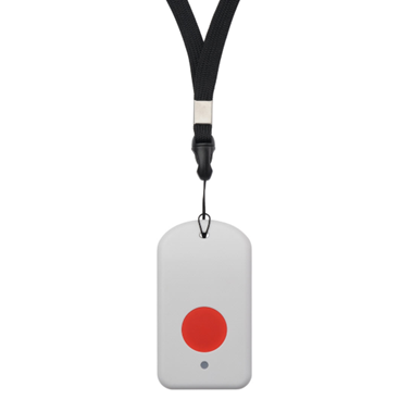
TrackerD is an Open Source LoRaWAN Tracker based on ESP32 MCU and Semtech LoRa Wireless Chip.
In TrackerD, there are various sensors such as GPS, WiFi, BLE, Temperature, Humidity, Motion Detection, and Buzzer. User can use TrackerD for different tracking scenario.
TrackerD is program friendly. Developers can use Arduino IDE to customize the software of TrackerD to fit their IoT solution.
The LoRa wireless technology used in TrackerD allows the user to send data and reach extremely long ranges at low data-rates. It provides ultra-long range spread spectrum communication and high interference immunity whilst minimizing current consumption. It targets professional tracking services.
TrackerD is equipped with a 1000mAh Li-on rechargeable battery. Each TrackerD has a worldwide unique OTAA keys to join the LoRaWAN network.

Note: LoRaWAN server can be a general LoRaWAN server other than TTN.
1.2 Specifications
Micro Controller:
- Espressif ESP32 PICO D4
- MCU: ESP32 PICO D4
- Bluetooth: Bluetooth V4.2 BR/EDR and Bluetooth LE
- WiFi : 802.11 b/g/n (802.11n up to 150 Mbps)
- Integrated SPI flash : 4 MB
- RAM: 448 KB
- EEPROM: 520 KB
- Clock Speed: 32Mhz
Common DC Characteristics:
- Supply Voltage: 5V via USB port or Internal li-on battery
- Operating Temperature: -40 ~ 60°C
LoRa Spec:
- Frequency Range,
- Band 1 (HF): 862 ~ 1020 Mhz
- 168 dB maximum link budget.
- +20 dBm - 100 mW constant RF output vs.
- +14 dBm high efficiency PA.
- Programmable bit rate up to 300 kbps.
- High sensitivity: down to -148 dBm.
- Bullet-proof front end: IIP3 = -12.5 dBm.
- Excellent blocking immunity.
- Low RX current of 10.3 mA, 200 nA register retention.
- Fully integrated synthesizer with a resolution of 61 Hz.
- FSK, GFSK, MSK, GMSK, LoRaTM and OOK modulation.
- Built-in bit synchronizer for clock recovery.
- Preamble detection.
- 127 dB Dynamic Range RSSI.
- Automatic RF Sense and CAD with ultra-fast AFC.
- Packet engine up to 256 bytes with CRC.
- LoRaWAN 1.0.3 Specification
Battery:
- 1000mA Li-on Battery power (for model TrackerD)
Power Consumption
- Sleeping Mode: 200uA
- LoRa Transmit Mode: 125mA @ 20dBm 44mA @ 14dBm
- Tracking: max: 38mA
1.3 Features
- LoRaWAN 1.0.3 Class A
- ESP32 PICO D4
- SX1276/78 Wireless Chip
- Arduino IDE Compatible
- Open source hardware / software
- Regular/ Real-time GPS,BLE,WIFI tracking
- Built-in3 axis accelerometer (LIS3DH)
- Humidity / temperature sensor : GXCAS Technology GXHT3X
- Motion sensing capability
- Power Monitoring
- Charging circuit via USB port
- 1000mA Li-on Battery power
- Tri-color LED, Alarm button
- Datalog
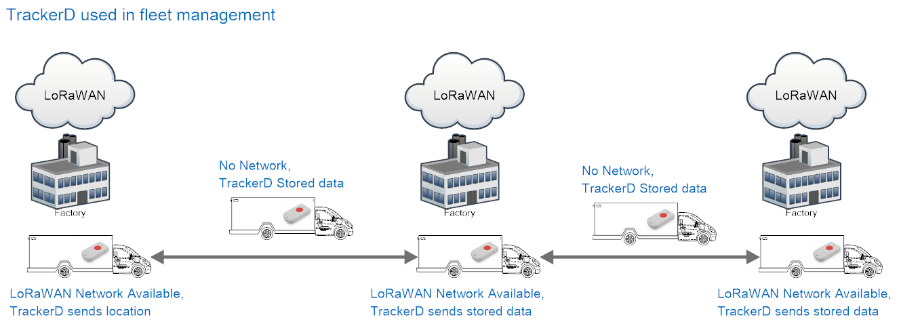
1.4 Applications
- Logistics and Supply Chain Management
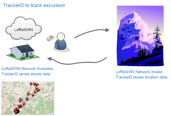
- Human tracking
2.1 Use TrackerD
2.1 How it works?
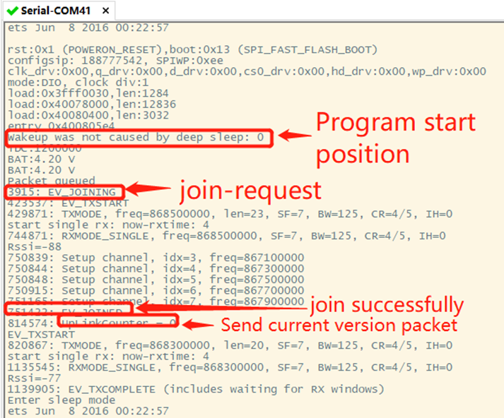
TrackerD is configured as LoRaWAN OTAA Class A GPS tracker by default. It has OTAA keys to join LoRaWAN network. To connect a LoRaWAN network, user need to input the OTAA keys in the LoRaWAN IoT server and push reset button of TrackerD (next to USB port). TrackerD will wake up and auto join the network via OTAA.
2.2 Quick guide to connect to LoRaWAN server
Here is an example for how to join the TTNv3 LoRaWAN Network. Below is the network structure, we use LPS8N as LoRaWAN gateway in this example.
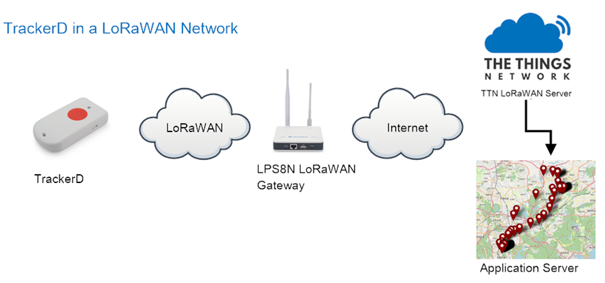
The LPS8N is already set to connect to TTN V3 network . What the rest need to is register this device in TTN V3:
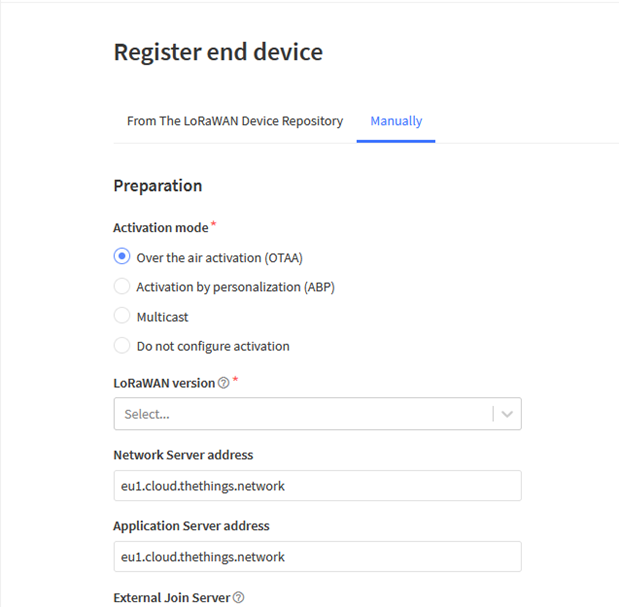
Step 1: Create a device in TTN V3 with the OTAA keys from TrackerD.
Each TrackerD is shipped with a sticker with the default device EUI as below:
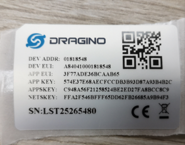
Input these keys to their LoRaWAN Server portal. Below is TTN V3 screen shot:
Add APP EUI in the application:
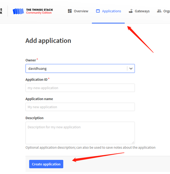
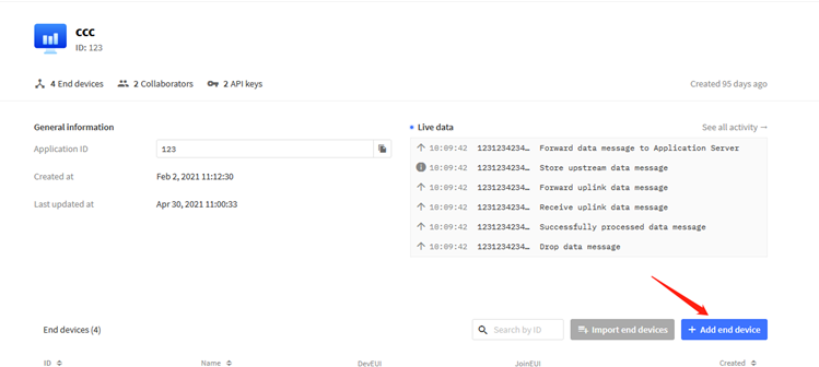
Add APP KEY and DEV EUI:

Step 2: Power on TrackerD by using the on board switch.
Step 3: TrackerD will auto join to the LoRaWAN network. After join success, TrackerD will start to upload message to IoT server.
2.3 Positioning Mode(SMOD)
Users can set TrackerD to different Positioning Mode for different applications. Below mod are supported.
- GPS ONLY(Factory Settings): only get and uplink GPS location info.
- BLE ONLY: Only obtain iBeacon info via BLE and uplink. Design for Indoor tracking.
- GPS/BLE Hybrid: Combination for Indoor and Outdoor tracking.Devices will try to search BLE iBeacon first. If device can't find the iBeacon, it will use GPS for positioning.
Users can switch modes by changing SMOD.
2.4 Uplink Payload
2.4.1 Uplink FPORT=5, Device Status
Uplink the device configures with FPORT=5. Once TrackerD Joined the network, it will uplink this message to the server. After the first uplink, TrackerD will uplink Device Status every 12 hours.
Use can also get the Device Status uplink through the downlink command: Downlink: 0x2301
| Size(bytes) | 1 | 2 | 1 | 1 | 2 | 2 | 1 |
|---|---|---|---|---|---|---|---|
| Value | Sensor Model | Firmware Version | Frequency Band | Sub-band | BAT | SMOD | Status |
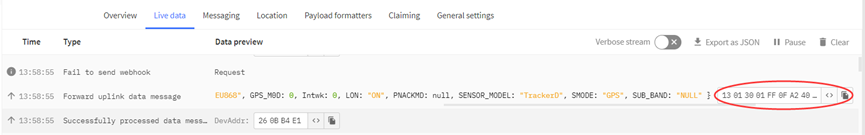
Example of Device Status: 13014001FF0FA24002
Sensor Model: For TrackerD,this value is 0x13
Firmware Version: 0x0140,Means:v1.4.0 version
Frequency Band:
*0x01: EU868
*0x02: US915
*0x03: IN865
*0x04: AU915
*0x05: KZ865
*0x06: RU864
*0x07: AS923
*0x08: AS923-1
*0x09: AS923-2
*0x0a: AS923-3
Sub- Band:value 0x00~0x08(only forAU915,US915,Others are 0xFF)
BAT: shows the battery voltage for TrackerD.
Ex1: 0x0FA2 = 4002mV
Use can also get the Device Status uplink through the downlink command:
SMOD Field (total 1 byte):0x40
| Size(bit) | 2bits | 2bit | 4bit |
| Value | SMOD | GPS_Settings | BLE_Settings |
SMOD:
1 : GPS ONLY
2 : BLE ONLY
3 : GPS/BLE Hybrid
GPS_MOD: Define how to send GPS payload
0 : Enable uploading on-board Temperature and humidity values
1 : Disable uploading on-board Temperature and humidity values
BLE_Settings:
1: BLE Positioning with Strongest iBeacon
Status Field (total 1 byte): 0x02
| Size(bit) | 5 Bits | 1 Bit | 1 Bit | 1 Bit |
| Value | Reserve | PNACKMD | LON | Transport Mode |
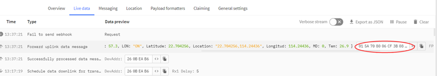
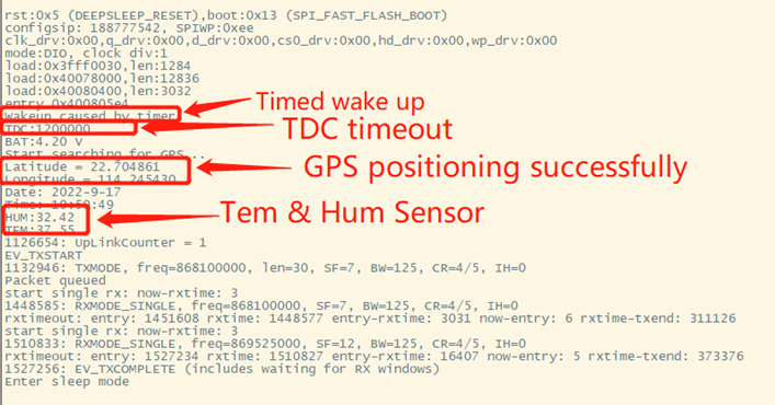
2.4.2 Uplink FPORT=2, Realtime GNSS Positioning + Temperature & Humidity
Users can use AT+SMOD=1,0,0 to enable uploading on-board Temperature and humidity values, and the total payload will be 15 bytes,
Size(bytes) | 4 | 4 | 2 | 1 | 2 | 2 |
|---|---|---|---|---|---|---|
| Value | Latitude | Longitude | FLAG | Hum | Tem |
Alarm & BAT:
| Size(bit) | 1 bit | 1bit | 14bits |
|---|---|---|---|
| Value | reserve | Alarm Indicate | BAT |
FLAG:
| Size(bit) | 2bits | 1bit |
|---|---|---|
| Value | MOD | LON |
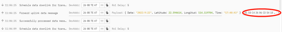
Example: Payload: 0x02863D68 FAC29BAF 4B45 60 0202 011A
Location info:
- Latitude: 02863D68 ⇒ if (0x02863D68& 0x80000000 = 0 ): value = 02863D68 /1000000 = 42.351976
- Longitude: FAC29BAF ⇒ if (0xFAC29BAF & 0x80000000 = 1 ): value = (0xFAC29BAF – 0x 100000000)/1000000 =-87.909457
Important note:
1. When power is low (<2.84v), GPS won't be able to get location info and GPS feature will be disabled and the location field will be filled with 0x0FFFFFFF, 0x0FFFFFFF.
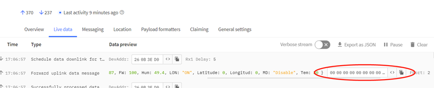
2. In this mode, the total payload will be 15 bytes, while US915/AU915 DR0 accepts only 11 bytes payload. In this case, the payload on server will be ignore and shows as below:
3. While GPS can't get location info after timeout(FTIME Parameter), the latitude and longitude will be filled with all 0x00:
Alarm:
Example: 0x4B & 0x40 >> 6 = 0x01
BAT:
Example: 0x4B45 & 0x3FFF ⇒ 2885 (mV).
The battery info shows the battery voltage, User can use the below mapping to indicate the battery in percentage: \
- > 4.0v : 80% ~ 100%
- 3.85v ~3.99v: 60% ~ 80%
- 3.70v ~ 3.84v: 40% ~ 60%
- 3.40v ~ 3.69v: 20% ~ 40%
- < 3.39v: 0~20%
MOD:
Example: (0x60>>6) & 0x3f =1
Set the format of GPS data uplink link:
0x00: Enable uploading on-board Temperature and humidity values
0x01: Disable uploading on-board Temperature and humidity values
Set the format of BLE data uplink link:
0x01: BLE Positioning with Strongest iBeacon
LON:
Example: (0x60>>5) & 0x01=1.
Enable/Disable LED activity for uplink
0x00: Disable LED indicator.
0x01: Enable LED indicator (Default Value)
Hum:
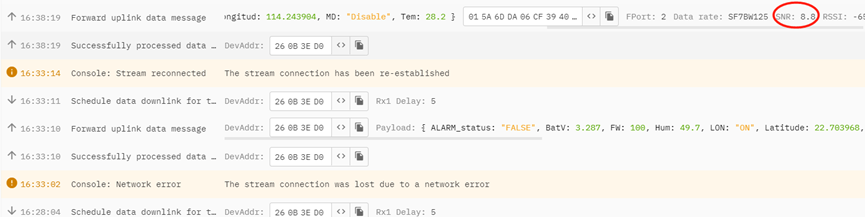
0202 = if (0x0202 & 0x8000 = 0 ): value = 0x0202 / 100 = +514 ⇒ 51.4 degree
Tem:
011A =if (0x011A & 0x8000 = 1 ): value =( 0x011A - 0x10000)/10(dec) ⇒ -28.2 degree
2.4.3 Uplink FPORT=3, Realtime GNSS Positioning (Default Mode)
The default uplink payload includes total 11 bytes (AT+SMOD=1,1,0). The payload is the first 11 bytes of Uplink FPORT=2, real-time GNSS positioning, (remove the temp and humidity)
Size(bytes) | 4 | 4 | 2 | 1 |
|---|---|---|---|---|
| Value | Latitude | Longitude | FLAG |

2.4.4 Uplink FPORT=4, History GNSS Positioning
Set PNACKMD=1, and TrackerD will wait for ACK for every uplink, when there is no LoRaWAN network, TrackerD will mark these records with non-ack messages and store the sensor data, and it will send all messages (10s interval) after the network recovery.
Note for this mode:
- a) TrackerD will do an ACK check for data records sending to make sure every data arrive server.
- b) TrackerD will send data in CONFIRMED Mode when PNACKMD=1, but TrackerD won't re-transmit the packet if it doesn't get ACK, it will just mark it as a NONE-ACK message. In a future uplink, if TrackerD gets an ACK, TrackerD will consider there is a network connection and resend all NONE-ACK Messages.
- c) the total payload will be 15 bytes, while US915/AU915 DR0 accepts only 11 bytes of payload. In this case (DR0 of US915/AU915), the payload on server will show NULL
The payload is 15 bytes, as below.
Size(bytes) | 4 | 4 | 2 | 1 | 1 | 1 | 1 | 1 |
|---|---|---|---|---|---|---|---|---|
| Value | Latitude | Longitude | Year | Month | Day | Hous | Min | Sen |
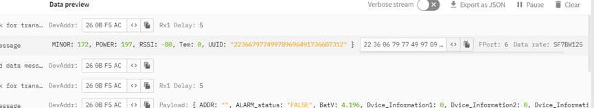
2.4.5 Uplink FPORT=6, BLE Positioning with Strongest iBeacon
TrackerD supports BLE scans for indoor positioning. User can set SMOD to BLE pure or GPS/BLE hybrid so TrackerD will scan BLE iBeacon and find the strongest iBeacon info and uplink.
User can set BLEMASK so TrackerD will only search the iBeacons which have UUID that match the BLEMASK settings.
Size(bytes) | 16 | 4 | 4 | 2 | 4 | 2 | 1 |
|---|---|---|---|---|---|---|---|
| Value | UUID | iBeacon MAJOR | iBeacon MINOR | iBeacon Measured Power | iBeacon RSSI | FLAG |
- BAT: Ex1:0x4B45 & 0x3FFF ⇒ 3901 (mV).
- MODE: Define the payload format.
- UUID: The uuid from the strongest iBeacon.
- MAJOR: The MAJOR from the strongest iBeacon.
- MINOR: The MAJOR from the strongest iBeacon.
- Measured Power: The Measured Power from the strongest iBeacon.
- RSSI: The RSSI from the strongest iBeacon.
2.4.6 Add Payload format in TTN V3
In TTN V3, use can add a custom payload so it shows friendly.
In the page Applications --> Payload Formats --> Custom --> decoder
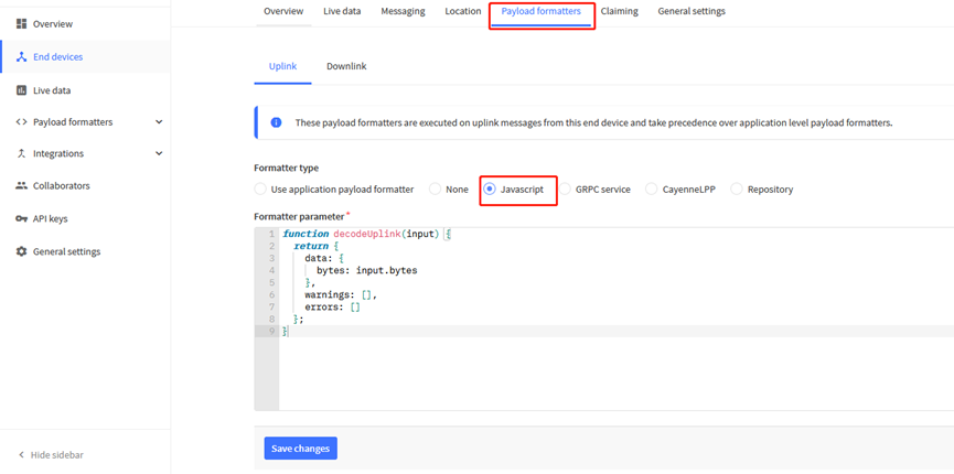
Add the decoder from this link:
https://github.com/dragino/dragino-end-node-decoder/tree/main/TrackerD
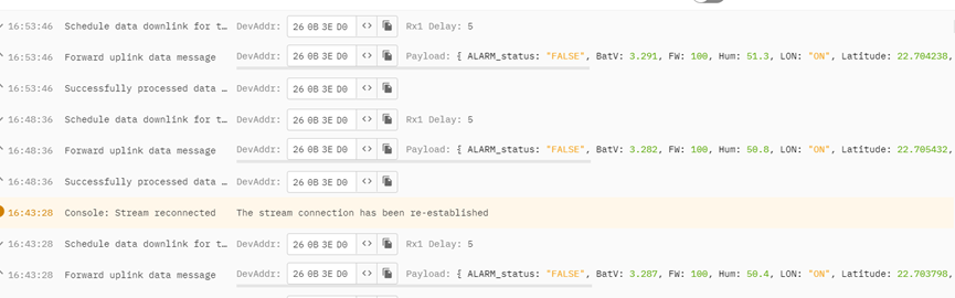
Save the change the uplink message will be parsed. As below:
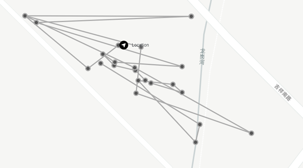
2.5 Integrate with Datacake
After TrackerD sends data to LoRaWAN server such as TTN, use can pass the data to Datacake and plot out, currently only support GPS plot.
Instruction is here: http://wiki.dragino.com/xwiki/bin/view/Main/Notes%20for%20Data%20Cake/#H7.Example--AddTrackerDGPSTrackingInDataCake
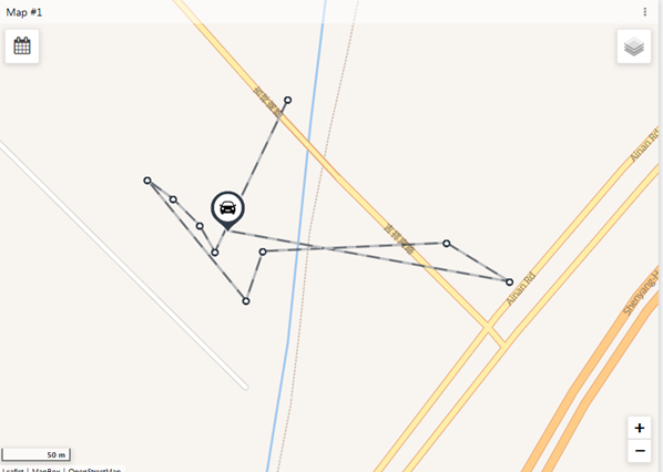
2.6 Integrate with Tago
After TrackerD sends data to LoRaWAN server such as TTN, user can pass the data to Datacake and plot out, currently only support GPS plot.
Instruction is here: http://wiki.dragino.com/xwiki/bin/view/Main/Tago.IO/#H3.A0Example-CreateTrackerD2FLGT92positioningwidget
2.7 Datalog Feature
total 273 entries,by default,
User can set PNACKMD=1, to enable Datalog feature.
Example use case.
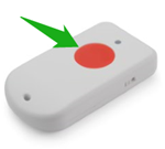
2.8 Alarm Mode
User can push the RED button by more than 5 seconds to enter Alarm Mode.
Once enter Alarm mode, the GREEN LED will flash 3 times, the buzzer will alarm for 5 seconds, then TrackerD will immediately send a packet without location info and then send a data packet with GPS positioning information. After that, the device will send 60 packets at 1-minute intervals. The Alarm flag in the payload will be set for the next 60 packets unless exits alert mode.
Two ways to exit alarm mode:
- Server sends a downlink command to exit.
- User fast press the RED button 10 times.
When exit alarm mode, RED LED will light up for 5 seconds, indicating that the alarm mode is exited. And the alert flag will be set to false.
2.9 Transport Mode
In Transport Mode, TrackerD will check if there is motion. If there is no motion, device will send uplinks every 20 minutes. If there is motion, device will send uplink every 5 minutes.
2.10 LED Status
| Event | Action | AT+LON to control on/off |
|---|---|---|
| Power On | BLUE, RED , Green flash once | N/A |
| Join request | Green led fast blink once (200ms) | Yes |
| Join Success | Green led on 5 second | N/A |
| Fixing Location | BLUE blinks 200ms per second | Yes |
| Fixed and uplink | GREEN **blinks twice (200ms per blink) | Yes |
| Fail Fix and uplink | RED blinks twice (200ms per blink) | Yes |
| Enter Alarm mode | RED on for 3 seconds | Yes |
| Uplink under Alarm | RED on for 1 second | Yes |
| Exit Alarm | BLUE led on 5 second | Yes |
| Get Downlink | GREEN led on 1 second | Yes |
| Movement Detect | RED led on 500ms | N/A |
2.11 Button Function
RESET button:
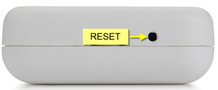
Push this button will reboot the device. Device will exit alarm mode and re-join to LoRaWAN server.
RED button:
| Function | Action | Description |
|---|---|---|
| Send Alarm | Keep Pressing RED button for more than 5 seconds | Enter Alarm Mode. See Alarm Mode |
| Exit Alarm Mode | Fast press the RED button 10 times | Exit Alarm Mode |
| Enter Deep Sleep Mode | Press and hold the button for 10 seconds, then quickly press the device 3 times to enter deep sleep | This is the mode ship out from factory. CPU will be complete in sleep mode and no LoRa activity, only use before deploy. |
2.12 USB Port Function
The USB interface of TrackerD has below functions:
- Power on the device
- Recharge the battery
- Configure Device
- Upgrade Firmware
3. Configure TrackerD via AT command or LoRaWAN downlink
User can configure TrackerD via AT Command or LoRaWAN Downlink.
LoRaWAN Downlink instruction for different platforms: IoT LoRaWAN Server
3.1 Access AT Command
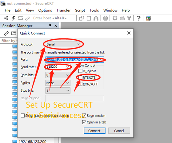
TrackerD supports the AT command set in stock firmware. User can connect to TrackerD with TYPE-C cable to use AT commands as shown below.
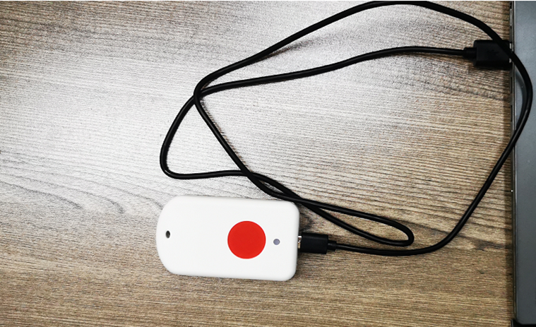
In PC, User needs to set serial tool baud rate to 115200 to access serial console for TrackerD. TrackerD will output system info once power on and user will be able to send AT commands:
3.2 Command Set
3.2.1 Set Transmit Interval
Set device uplink interval.
- AT Command:
AT+TDC=xxx
Example: AT+TDC=300000. Means set interval to 5 minutes(300 seconds)
- Downlink Payload (prefix 0x01):
0x01 00 01 2C // Same as AT+TDC=300000
3.2.2 Set Alarm Packet transmission interval
Set alarm packet transmit interval
- AT Command:
AT+ATDC=xx.
Example: AT+ATDC=60000 --> Set Alarm Packet Interval to 60 seconds. TrackerD will send every 60 seconds in Alarm mode, Default Value: 60000
- Downlink Payload (prefix 0xB1):
0xB1 00 00 3C // Same as AT+ATDC=60000
3.2.3 Set Transport Mode Packet transmission interval
Set Transport Mode packet transmit interval
- AT Command:
AT+MTDC=xx.
Example: AT+MTDC=300000 --> Set Transport Mode Packet Interval to 300 seconds. TrackerD will send every 300 seconds in Transport mode, Default Value: 300000
- Downlink Payload (prefix 0x03):
0x03 00 01 2C // Same as AT+ MTDC=3000000
3.2.4 Exit Alarm
Server send downlink command to exit Alarm mode
- AT Command: No AT Command
- Downlink Payload (prefix 0x02):
0x02 01 // Exit Alarm Mode
3.2.5 Disable/Enable LED flash
Disable/Enable LED for position, downlink and uplink
- AT Command:
AT+LON=xx. (Disable (0), Enable (1), default:1)
Example: AT+LON=0 --> Disable LED for position, downlink and uplink.
- Downlink Payload (prefix 0xAE):
0xAE 00 // Same as AT+LON=0
3.2.6 Disable/Enable Transport Mode
Users can use this feature to enable/disable Transport Mode.
- AT Command:
AT+INTWK=xx. (Disable (0), Enable (1), default:0)
Example: AT+ INTWK =1 --> Enable Transport Mode.
- Downlink Payload (prefix 0xAF):
0xAF 01 // Same as AT+ INTWK =1
3.2.7 Set Positioning Mode
SMOD define how TrackerD scan and uplink data:
- AT Command:
AT+SMOD=aa,bb,cc
aa:
- 1: GPS ONLY(Factory Settings): only get and uplink GPS location info.
- 2: BLE ONLY: Only obtain iBeacon info via BLE and uplink. Design for Indoor tracking.
- 3: GPS/BLE Hybrid: Combination for Indoor and Outdoor tracking.Devices will try to search BLE iBeacon first. If device can't find the iBeacon, it will use GPS for positioning.
bb:
- 0 : GPS+ BAT+ State+Tem&Hum
- 1 : GPS +BAT State
cc:
- 1 : (iBeacon)UUID+ Major + Minor+Power+Rssi+BAT+State
Example:
AT+ SMOD =1,0,0 --> GPS+ BAT+ State+Tem&Hum
AT+ SMOD =1,1,0 --> GPS +BAT State
AT+ SMOD =2,0,1 --> (iBeacon)UUID+ Major + Minor+Power+Rssi+BAT+State
- Downlink Payload (prefix 0xA5):
0xA5 01 00 00 // Same as AT+ SMOD =1,0,0
3.2.8 Set MAX GPS position time
Set max positioning time, default is 150 seconds. TrackerD will try to get location info within this period. If fail to get position data within this time, TrackerD will use 000000 for latitude and longitude.
If AT+FTIME=0. The GPS module will be always powered and positioning. This will highly increase the power consumption (up to 50mA). When AT+FTIME=0, it will improve fix accuracy and shorten the acquire time for next uplink.
- AT Command:
AT+FTIME=xx --> Set to use xx as max fix time.
Example: AT+FTIME=150
- Downlink Payload (prefix 0xAA):
0xAA 00 96 // Set AT+FTIME=150
3.2.9 Set PDOP value for GPS fix accuracy
PDOP(Position Dilution of Precision) filter, TrackerD will only accept GPS data with a lower PDOP value than pre-configure PDOP value. If device can't get a valid GPS packet within FTIME timeout, it will use the GPS data with lowest PDOP value to server.
A GPS packet with lower PDOP has higher accuracy. PDOP default value is 2.0
- AT Command:
AT+PDOP=2.5 --> Set PDOP to 2.5
- Downlink Payload (prefix 0xAD):
0xAD 00 0A // Set AT+PDOP=1 (0x0A / 10 =1)
0xAD 00 19 // Set AT+PDOP=2.5 (0x19 / 10 =2.5)
0xAD 00 46 // Set AT+PDOP=7 (0x46 / 10 =7)
Disable/Enable the confirmation mode
- AT Command:
AT+CFM=xx
Example:
AT+ CFM=0 --> Disable confirmation
AT+ CFM=1 --> Enable confirmation
- Downlink Payload (prefix 0x05):
0x05 01 // Same as AT+ SMOD =1
3.2.10 Auto Send None-ACK messages
TrackerD will wait for ACK for each uplink, If TrackerD doesn't get ACK from the IoT server, it will consider the message doesn't arrive server and store it. TrackerD keeps sending messages in normal periodically. Once TrackerD gets ACK from a server, it will consider the network is ok and start to send the not-arrive message.
- AT Command: AT+PNACKMD
The default factory setting is 0.
Command Example Function Response:
AT+PNACKMD=1 // Poll None-ACK message OK
- Downlink Command: 0x34
Example: 0x3401 // Same as AT+PNACKMD=1
3.2.11 Set BLEMASK to filter BLE iBeacon
BLEMASK is to filter the unwanted BLE iBeacons during scan. For example, if BLEMASK is 123456. LBT1 will only uplink UUID info which includes 123456. It will ignore all other iBeacons which doesn’t contact 123456 in the UUID.
Note: BLEMASK range is 6 ~ 10 bytes. If AT+BLEMASK < 6 bytes, BLEMASK will be disabled.
AT Command:
AT+BLEMASK=123456 // Set BLEMASK = 123456
AT+BLEMASK=0 // disable BLEMASK
Downlink Payload: (Prefix : 0xA5)
Example:
0xA5010203040506 // Set BLEMASK to 123456
4. Setting for Different Scenarios
5. Upload Firmware
5.1 Firmware Change Log
5.2 How to upgrade firmware
User can use the TrackerD's USB port to upgrade firmware into it. The hardware connection for upgrade firmware is as below:
Step1: Connect TrackerD and PC via USB cable shipped with TrackerD.
Step2: Install CH9102 driver in the PC.
After installation of the driver and plug in TrackerD, user should be able to see com port in PC's device manager.
Step3: Download and Install Flash Tool: https://www.espressif.com.cn/en/support/download/other-tools?keys=Flash%2BDownload%2BTools
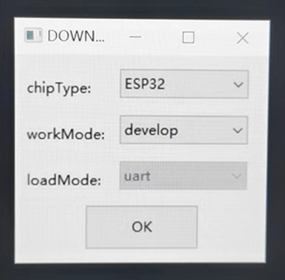
Step4: Run Flash Download Tool and configure chip type to ESP32
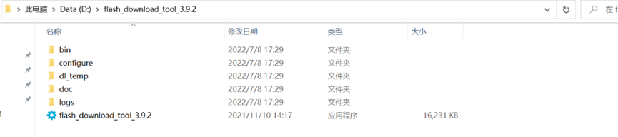
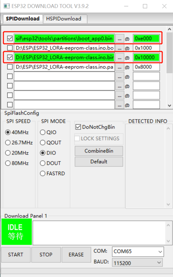
Step5: Select the firmware file (.bin format), com port and proper SPI configure. Clink Start. Bin file location:
https://github.com/dragino/TrackerD/releases
Users need to use below files:
boot_app0.bin @0e000
ESP_LORA-eeprom-class.bin @ 0x10000
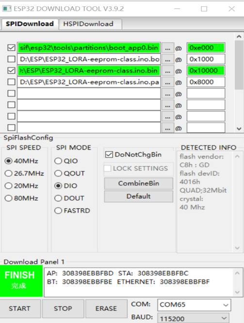
After upgrade finish, it will show finish as below:
6. Developer Guide
6.1 Compile Source Code
6.1.1 Set up ARDUINO compile environment
- Download the latest Arduino software (IDE) from the Arduino official website: https://www.arduino.cc/en/Main/Software
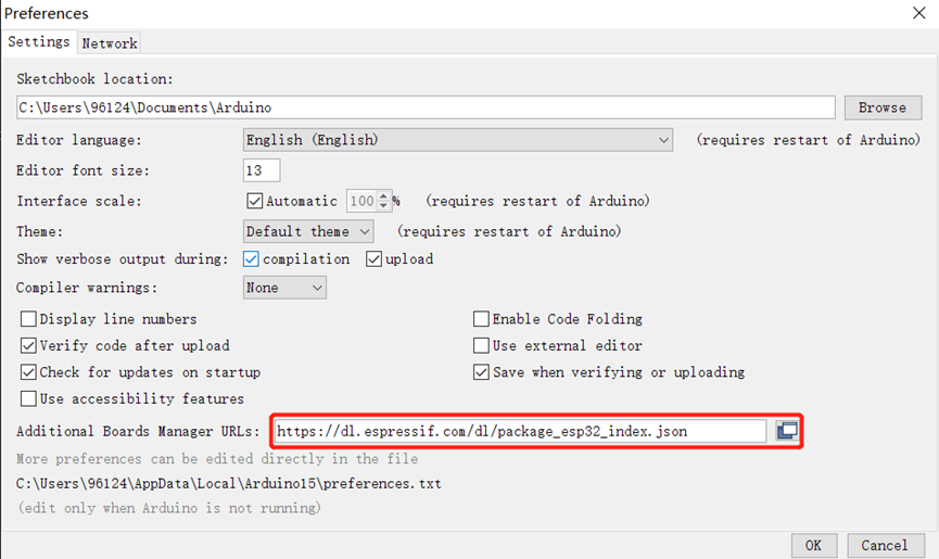
Install IDE on PC, open and click File --> Preference, add the following URL: https://dl.espressif.com/dl/package_esp32_index.json
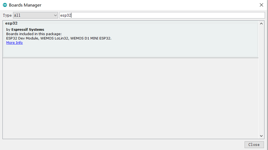
- Go to tools --> Boards --> Boards Manager, find the esp32 information and install it.
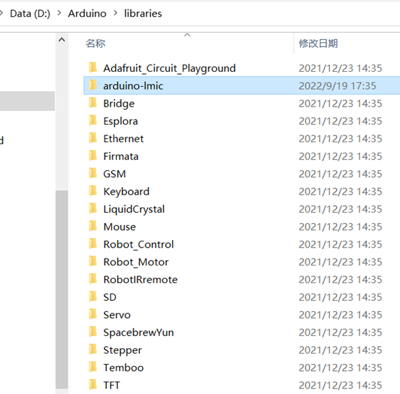
- Download the latest TrackerD from the dragino github: https://github.com/dragino/TrackerD
Put the Library in the TrackerD directory into the libraries file in the Arduino directory:
6.2 Source Code
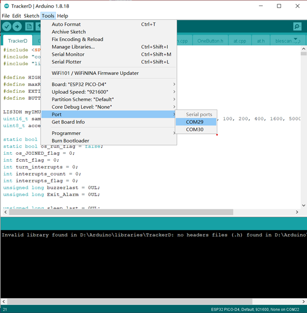
- Open the example in the TrackerD file, please select the correct port in the IDE, as shown below:
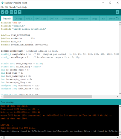
- Click to upload
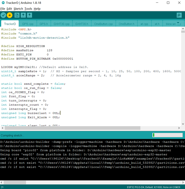
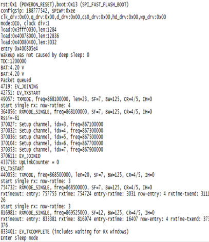
- Check the result, if the upload is successful, as shown below, open the serial port to view the data
7. FAQ
7.1 How to change the LoRa Frequency Bands/Region?
User can follow the introduction for how to upgrade image. When download the images, choose the required image file for download.
7.2 What is the pin mapping for the USB program cable?
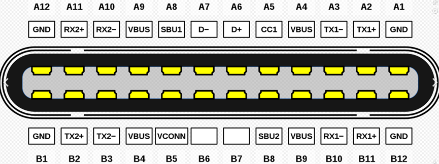
| Pin | Color | USB Pin |
|---|---|---|
| A4,B4,A9,B9 | Red | VCC |
| A7,B7 | White | D- (N/A) |
| A6,B6 | Green | D+(N/A) |
| A1,B1,A12,B12 | Black | GND |
| A5 | Purple | MTDC/GOIO13 |
| B5 | Blue | MTDC/GPIO12 |
| A8 | Yellow | MTMS/GPIO14 |
| B8 | Grey | MTDO/GPIO15 |
8. Order Info
Part Number: TrackerD-XXX
XXX: The default frequency band
- EU433: Default frequency band EU433
- EU868: Default frequency band EU868
- IN865: Default frequency band IN865
- KR920: Default frequency band KR920
- AS923: Default frequency band AS923
- AU915: Default frequency band AU915
- US915: Default frequency band US915
9. Packing Info
Package Includes:
- TrackerD LoRaWAN GPS/BLE Tracker x 1
- USB recharge & program cable x 1
Dimensions and Weight:
- Device Size: 85 x 48 x 15 cm
- Weight: 50g
10. Support
- Support is provided Monday to Friday, from 09:00 to 18:00 GMT+8. Due to different timezones we cannot offer live support. However, your questions will be answered as soon as possible in the before-mentioned schedule.
- Provide as much information as possible regarding your enquiry (product models, accurately describe your problem and steps to replicate it etc) and send a mail to support@dragino.com.
11. Reference