TrackerD -- LoRaWAN Tracker User Manual
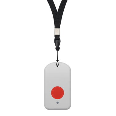
Table of Contents:
- 1. Introduction
- 2. Use TrackerD
- 2.1 How it works?
- 2.2 Quick guide to connect to LoRaWAN server
- 2.3 Positioning Mode(SMOD)
- 2.4 Uplink Payload
- 2.4.1 Uplink FPORT=5, Device Status
- 2.4.2 Uplink FPORT=2, Realtime GNSS Positioning + Temperature & Humidity
- 2.4.3 Uplink FPORT=3, Realti me GNSS Positioning (Default Mode)
- 2.4.4 Uplink FPORT=4, History GNSS Positioning
- 2.4.5 Uplink FPORT=6, BLE Positioning with Strongest iBeacon
- 2.4.6 Uplink FPORT=7, Alarm information status (Since firmware 1.4.4)
- 2.4.7 Uplink FPORT=8, WiFi Positioning with Strongest WiFi SSID (Since firmware 1.4.1)
- 2.4.8 Uplink FPORT=9, BLE Positioning with Multiple iBeacon(Since firmware 1.4.7)
- 2.4.9 Add Payload format in TTN V3
- 2.5 Integrate with Datacake
- 2.6 Integrate with Tago
- 2.7 Integrate with Node-red
- 2.8 Datalog Feature
- 2.9 Alarm Mode
- 2.10 Transport Mode
- 2.11 LED Status
- 2.12 Button Function
- 2.13 USB Port Function
- 2.14 Sleep Mode
- 3. Configure TrackerD via AT command or LoRaWAN downlink
- 3.1 Access AT Command
- 3.2 Command Set
- 3.2.1 Set Transmit Interval
- 3.2.2 Set Alarm Packet transmission interval
- 3.2.3 Set Transport Mode Packet transmission interval
- 3.2.4 Exit Alarm
- 3.2.5 Disable/Enable LED flash and buzzer
- 3.2.6 Disable/Enable Transport Mode
- 3.2.7 Set Positioning Mode
- 3.2.8 Set MAX GPS position time
- 3.2.9 Set PDOP value for GPS fix accuracy
- 3.2.10 Disable/Enable the confirmation mode
- 3.2.11 Auto Send None-ACK messages
- 3.2.12 Set BLEMASK to filter BLE iBeacon
- 3.2.13 Set WiFIMASK to filter WiFi SSID(Since firmware 1.4.1)
- 3.2.14 Disable/Enable Information printing(Since firmware 1.4.1)
- 3.2.15 Get or Set Eight Channels Mode, only for us915, AU915(Since firmware 1.4.1)
- 3.2.16 Get or Set Threshold for motion detect(Since firmware 1.4.3)
- 3.2.17 Set AT command window time(Since firmware 1.4.5)
- 3.2.18 Set the stepmeter mode(Since firmware 1.4.5)
- 3.2.19 Set down the decline detection mode(Since firmware 1.4.5)
- 3.2.20 Disable/Enable buzzer(Since firmware 1.4.6)
- 3.2.21 Set long press time(Since firmware 1.4.6)
- 3.2.22 Set the Bluetooth scan time(Since firmware 1.5.1)
- 3.2.23 Conversion of TrackerD and TrackerD-LS(Since firmware 1.4.9)
- 4. Setting for Different Scenarios
- 5. Upload Firmware
- 6. Developer Guide
- 7. FAQ
- 7.1 How to change the LoRa Frequency Bands/Region?
- 7.2 What is the pin mapping for the USB program cable?
- 7.3 Notes on using different serial port tools for TrackerD
- 7.4 How to modify source code to compile different frequency band bin file?
- 7.5 Are there example python example for BLE Indoor Positioning?
- 7.6 Can alert mode and transport mode be used together?
- 7.7 Can i get the datalog record from console?
- 7.8 FAQs for upgrading to version 1.4.9 or later
- 8 Trouble Shooting
- 8.1 TDC is changed to 4294947296 and cause no uplink.
- 8.2 Device not able get AT Command or show output after wake up from deep sleep mode
- 8.3 Problem after Upgrading Firmware
- 8.4 When positioning, it will restart or the PDOP setting is unsuccessful
- 8.5 How to deal with unsuccessful GPS positioning?
- 8.6 When upgrading the firmware, the data is not completely erased, and the information does not return to normal after multiple resets
- 8.7 If you encounter the following problems, please upgrade to the latest version
- 8.8 Why when using some serial consoles, only inputting the first string port console will return "error"?
- 8.9 When the device is connected to the serial port, it cannot send Uplink, the light color is abnormal, and it does not respond to commands.
- 9. Order Info
- 10. Packing Info
- 11. Support
- 12. Reference
1. Introduction
1.1 What is TrackerD
TrackerD is an Open Source LoRaWAN Tracker based on ESP32 MCU and Semtech LoRa Wireless Chip.
In TrackerD, there are various sensors such as GPS, WiFi, BLE, Temperature, Humidity, Motion Detection, and Buzzer. User can use TrackerD for different tracking scenario.
TrackerD is program friendly. Developers can use Arduino IDE to customize the software of TrackerD to fit their IoT solution.
The LoRa wireless technology used in TrackerD allows the user to send data and reach extremely long ranges at low data-rates. It provides ultra-long range spread spectrum communication and high interference immunity whilst minimizing current consumption. It targets professional tracking services.
TrackerD is equipped with a 1000mAh Li-ion rechargeable battery. Each TrackerD has a worldwide unique OTAA keys to join the LoRaWAN network.
Note: LoRaWAN server can be a general LoRaWAN server other than TTN.
1.2 Specifications
Micro Controller:
- Espressif ESP32 PICO D4
- MCU: ESP32 PICO D4
- Bluetooth: Bluetooth V4.2 BR/EDR and Bluetooth LE
- WiFi : 802.11 b/g/n (802.11n up to 150 Mbps)
- Integrated SPI flash : 4 MB
- RAM: 448 KB
- EEPROM: 520 KB
- Clock Speed: 32Mhz
Common DC Characteristics:
- Supply Voltage: 5V via USB port or Internal li-on battery
- Operating Temperature: -15℃ ~ 60°C
LoRa Spec:
- Frequency Range,
- Band 1 (HF): 862 ~ 1020 Mhz
- 168 dB maximum link budget.
- +20 dBm - 100 mW constant RF output vs.
- +14 dBm high efficiency PA.
- Programmable bit rate up to 300 kbps.
- High sensitivity: down to -148 dBm.
- Bullet-proof front end: IIP3 = -12.5 dBm.
- Excellent blocking immunity.
- Low RX current of 10.3 mA, 200 nA register retention.
- Fully integrated synthesizer with a resolution of 61 Hz.
- FSK, GFSK, MSK, GMSK, LoRaTM and OOK modulation.
- Built-in bit synchronizer for clock recovery.
- Preamble detection.
- 127 dB Dynamic Range RSSI.
- Automatic RF Sense and CAD with ultra-fast AFC.
- Packet engine up to 256 bytes with CRC.
- LoRaWAN 1.0.3 Specification
Battery:
- 1000mA Li-ion Battery power (for model TrackerD)
Power Consumption
- Sleeping Mode: 200uA
- LoRa Transmit Mode: 125mA @ 20dBm 44mA @ 14dBm
- Tracking: max: 38mA
1.3 Features
- LoRaWAN 1.0.3 Class A
- ESP32 PICO D4
- SX1276/78 Wireless Chip
- Arduino IDE Compatible
- Open source hardware / software
- Regular/ Real-time GPS,BLE,WIFI tracking
- Built-in3 axis accelerometer (LIS3DH)
- Humidity / temperature sensor : GXCAS Technology GXHT3X
- Motion sensing capability
- Power Monitoring
- Charging circuit via USB port
- 1000mA Li-ion Battery power
- Tri-color LED, Alarm button
- Datalog
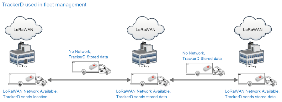
1.4 Applications
- Logistics and Supply Chain Management
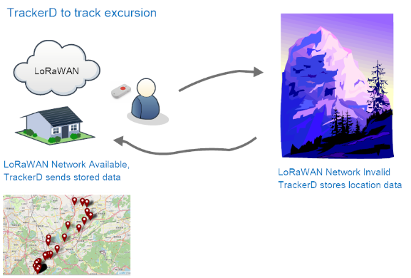
- Human tracking
2. Use TrackerD
2.1 How it works?
TrackerD is configured as LoRaWAN OTAA Class A GPS tracker by default. It has OTAA keys to join LoRaWAN network. To connect a LoRaWAN network, user need to input the OTAA keys in the LoRaWAN IoT server and push reset button of TrackerD (next to USB port). TrackerD will wake up and auto join the network via OTAA.
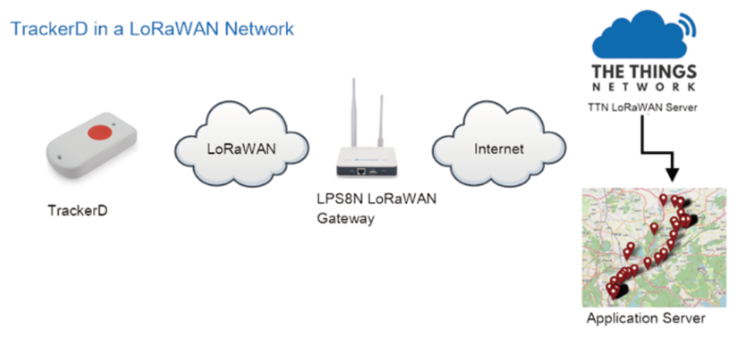
2.2 Quick guide to connect to LoRaWAN server
Here is an example for how to join the TTNv3 LoRaWAN Network. Below is the network structure, we use LPS8N as LoRaWAN gateway in this example.

The LPS8N is already set to connect to TTN V3 network . What the rest need to is register this device in TTN V3:
Step 1: Create a device in TTN V3 with the OTAA keys from TrackerD.
Each TrackerD is shipped with a sticker with the default device EUI as below:
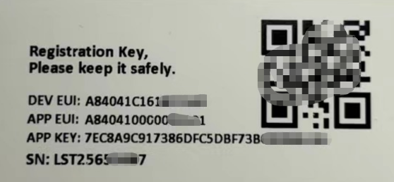
You can enter this key in the LoRaWAN Server portal. Below is TTN screen shot:
Create the application.


Add devices to the created Application.


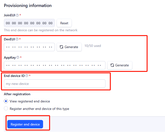
Enter end device specifics manually.

Add DevEUI and AppKey. Customize a platform ID for the device.
Step 2: Add decoder.
In TTN, user can add a custom payload so it shows friendly reading.
Click this link to get the decoder: https://github.com/dragino/dragino-end-node-decoder/tree/main/
Below is TTN screen shot:


Step 3: Push this button will activate this device.
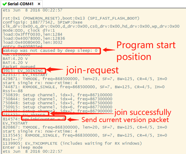
TrackerD will auto join to the LoRaWAN network. After join success, TrackerD will start to upload message to IoT server.
2.3 Positioning Mode(SMOD)
Users can set TrackerD to different Positioning Mode for different applications. Below mod are supported.
- GPS ONLY(Factory Settings): Only get and uplink GPS location info.
- BLE or WiFi ONLY: Only obtain iBeacon info via BLE and uplink or obtain wifi ssid info via WiFi and uplink. Design for Indoor tracking.
- GPS/BLE Hybrid: Combination for Indoor and Outdoor tracking. Devices will try to search BLE iBeacon first. If device can't find the iBeacon, it will use GPS for positioning.
Users can switch modes by changing SMOD.
2.4 Uplink Payload
2.4.1 Uplink FPORT=5, Device Status
Uplink the device configures with FPORT=5. Once TrackerD Joined the network, it will uplink this message to the server. After the first uplink, TrackerD will uplink Device Status every 12 hours.
Use can also get the Device Status uplink through the downlink command: Downlink: 0x2301
| Size(bytes) | 1 | 2 | 1 | 1 | 2 | 1 | 1 |
|---|---|---|---|---|---|---|---|
| Value | Sensor Model | Firmware Version | Frequency Band | Sub-band | BAT | SMOD | Status |
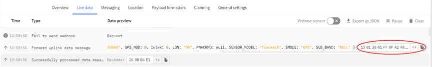
Example of Device Status: 13014001FF0FA24002
Sensor Model: For TrackerD,this value is 0x13
Firmware Version: 0x0140,Means:v1.4.0 version
Frequency Band:
0x01: EU868
0x02: US915
0x03: IN865
0x04: AU915
0x05: KZ865
0x06: RU864
0x07: AS923
0x08: AS923-1
0x09: AS923-2
0x0a: AS923-3
Sub-Band: value 0x00~0x08(only forAU915,US915,Others are 0xFF)
BAT: shows the battery voltage for TrackerD.
Ex1: 0x0FA2 = 4002mV
Use can also get the Device Status uplink through the downlink command:
SMOD Field (total 1 byte):0x40
| Size(bit) | 1 bit | 2 bits | 4 bits |
| Value | SMOD | GPS_Settings | BLE_Settings |
SMOD:
1 : GPS ONLY
2 : BLE ONLY
3 : GPS/BLE Hybrid
GPS_MOD: Define how to send GPS payload
0 : Enable uploading on-board Temperature and humidity values
1 : Disable uploading on-board Temperature and humidity values
BLE_Settings:
1: BLE Positioning with Strongest iBeacon
2: WiFi Positioning with Strongest WiFi SSID (V1.4.1 Version support this function later)
Status Field (total 1 byte): 0x02
| Size(bit) | 5 Bits | 1 Bit | 1 Bit | 1 Bit |
| Value | Reserve | PNACKMD | LON | Transport Mode |
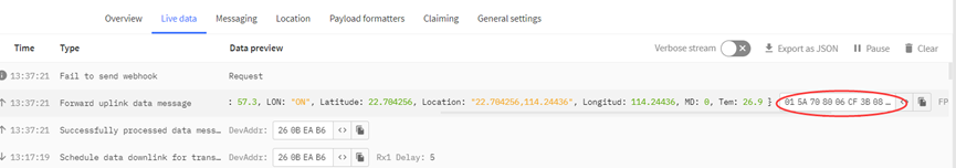
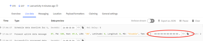
2.4.2 Uplink FPORT=2, Realtime GNSS Positioning + Temperature & Humidity
Users can use AT+SMOD=1,0,0 to enable uploading on-board Temperature and humidity values, and the total payload will be 15 bytes,
| Size(bytes) | 4 | 4 | 2 | 1 | 2 | 2 |
| Value | Latitude | Longitude | FLAG | Hum | Tem |
Alarm & BAT:
| Size(bit) | 1 bit | 1 bit | 14 bits |
| Value | reserve | Alarm Indicate | BAT |
FLAG:
| Size(bit) | 2 bits | 1 bit |
| Value | MOD | LON |
Example: Payload: 0x02863D68 FAC29BAF 4B45 60 0202 011A
Location info:
- Latitude: 02863D68 ⇒ if (0x02863D68& 0x80000000 = 0 ): value = 02863D68 /1000000 = 42.351976
- Longitude: FAC29BAF ⇒ if (0xFAC29BAF & 0x80000000 = 1 ): value = (0xFAC29BAF – 0x 100000000)/1000000 =-87.909457
Important note:
1. When power is low (<2.84v), GPS won't be able to get location info and GPS feature will be disabled and the location field will be filled with 0x0FFFFFFF, 0x0FFFFFFF.
2. In this mode, the total payload will be 15 bytes, while US915/AU915 DR0 accepts only 11 bytes payload. In this case, the payload on server will be ignore and shows as below:
3. While GPS can't get location info after timeout(FTIME Parameter), the latitude and longitude will be filled with all 0x00:
Alarm:
Example: 0x4B & 0x40 >> 6 = 0x01
BAT:
Example: 0x4B45 & 0x3FFF ⇒ 2885 (mV).
The battery info shows the battery voltage, User can use the below mapping to indicate the battery in percentage: \
- > 4.0v : 80% ~ 100%
- 3.85v ~3.99v: 60% ~ 80%
- 3.70v ~ 3.84v: 40% ~ 60%
- 3.40v ~ 3.69v: 20% ~ 40%
- < 3.39v: 0~20%
MOD:
Example: (0x60>>6) & 0x3f =1
Set the format of GPS data uplink link:
0x00: Enable uploading on-board Temperature and humidity values
0x01: Disable uploading on-board Temperature and humidity values
Set the format of BLE data uplink link:
0x01: BLE Positioning with Strongest iBeacon
LON:
Example: (0x60>>5) & 0x01=1.
Enable/Disable LED activity for uplink
0x00: Disable LED indicator.
0x01: Enable LED indicator (Default Value)
Hum:
0230 value = 0x0230 / 10 = 560 ⇒ 56%
Tem:
0202 = if (0x0202 & 0x8000 = 0 ): value = 0x0202 / 100 = +514 ⇒ 5.14 degree
011A =if (0xF11A & 0x8000 = 1 ): value =( 0xF11A - 0x10000)/100(dec) ⇒ -38.14 degree
2.4.3 Uplink FPORT=3, Realti me GNSS Positioning (Default Mode)
The default uplink payload includes total 11 bytes (AT+SMOD=1,1,0). The payload is the first 11 bytes of Uplink FPORT=2, real-time GNSS positioning, (remove the temp and humidity)
| Size(bytes) | 4 | 4 | 2 | 1 |
| Value | Latitude | Longitude | FLAG |

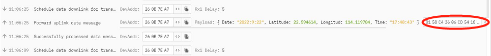
2.4.4 Uplink FPORT=4, History GNSS Positioning
Set PNACKMD=1, and TrackerD will wait for ACK for every uplink, when there is no LoRaWAN network, TrackerD will mark these records with non-ack messages and store the sensor data, and it will send all messages (10s interval) after the network recovery.
Note for this mode:
- a) TrackerD will do an ACK check for data records sending to make sure every data arrive server.
- b) TrackerD will send data in CONFIRMED Mode when PNACKMD=1 and CFM=1, but TrackerD won't re-transmit the packet if it doesn't get ACK, it will just mark it as a NONE-ACK message. In a future uplink, if TrackerD gets an ACK, TrackerD will consider there is a network connection and resend all NONE-ACK Messages.
- c) the total payload will be 15 bytes, while US915/AU915 DR0 accepts only 11 bytes of payload. In this case (DR0 of US915/AU915), the payload on server will show NULL
- d) The location time is in GMT(UTC+0).
The payload is 15 bytes, as below.
| Size(bytes) | 4 | 4 | 2 | 1 | 1 | 1 | 1 | 1 |
| Value | Latitude | Longitude | Year | Month | Day | Hous | Min | Sen |
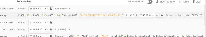
2.4.5 Uplink FPORT=6, BLE Positioning with Strongest iBeacon
TrackerD supports BLE scans for indoor positioning. User can set SMOD to BLE pure or GPS/BLE hybrid so TrackerD will scan BLE iBeacon and find the strongest iBeacon info and uplink.
User can set BLEMASK so TrackerD will only search the iBeacons which have UUID that match the BLEMASK settings.
| Size(bytes) | 16 | 2 | 2 | 1 | 1 | 2 | 1 | 1 | 1 |
| Value | UUID | iBeacon MAJOR | iBeacon MINOR | senseless | RSSI of the device within 1m | iBeacon Measured Power | iBeacon RSSI | FLAG |
- BAT: Ex1:0x4B45 & 0x3FFF ⇒ 3901 (mV).
- MODE: Define the payload format.
- UUID: The uuid from the strongest iBeacon.
- MAJOR: The MAJOR from the strongest iBeacon.
- MINOR: The MINOR from the strongest iBeacon.
- Measured Power: The Measured Power from the strongest iBeacon.
- RSSI: The RSSI from the strongest iBeacon.
- RSSI_1M: RSSI of the device within 1m.
2.4.6 Uplink FPORT=7, Alarm information status (Since firmware 1.4.4)
The upward link device is configured to FPORT = 7. Once Trackerd alarm, it will upload the news to the server.
| Size(bytes) | 2 | 1 |
| Value | Alarm & BAT | Mod+lon |

alarm=(bytes[0] & 0x40) // Alarm status
batV=(((bytes[0] & 0x3f) <<8) | bytes[1])/1000; // Battery,units:V
mod = bytes[2] & 0xC0;
Lon=(bytes[2] & 0x20)
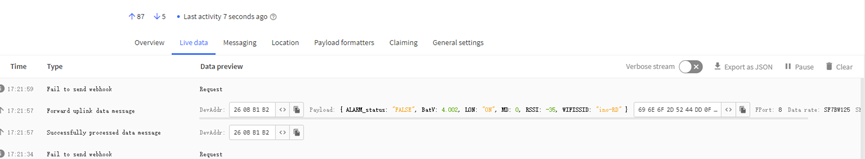
2.4.7 Uplink FPORT=8, WiFi Positioning with Strongest WiFi SSID (Since firmware 1.4.1)
TrackerD supports WiFi scans for indoor positioning. User can set SMOD to WiFi so TrackerD will scan WiFi and find the strongest WiFi info and uplink.
Size(bytes) | 6 | 4 | 2 | 1 |
| Value | SSID | RSSI | FLAG |
- BAT: Ex1:0x4B45 & 0x3FFF ⇒ 3901 (mV).
- SSID: WiFi name.
- RSSI: The RSSI from the strongest WiFi.
2.4.8 Uplink FPORT=9, BLE Positioning with Multiple iBeacon(Since firmware 1.4.7)
TrackerD supports BLE scanning for indoor positioning. Users can set SMOD to BLE pure or GPS/BLE Hybrid, so TrackerD will scan up to 40 BLE iBeacons and send uplinks.
User can set BLEMASK so TrackerD will only search the iBeacons which have UUID that match the BLEMASK settings.
| Size(bytes) | 2 | 1 | 2 | 2 | 1 | 2 | 2 | 1 | ... |
| Value | Alarm & BAT | FLAG | iBeacon MAJOR | iBeacon MINOR | iBeacon RSSI | iBeacon MAJOR | iBeacon MINOR | iBeacon RSSI | ... |

- BAT: Ex1:0x4B45 & 0x3FFF ⇒ 3901 (mV).
- MAJOR: The MAJOR from the strongest iBeacon.
- MINOR: The MINOR from the strongest iBeacon.
- RSSI: The RSSI from the strongest iBeacon.
- MOD: Bluetooth mode: 1: Search the beacon with the strongest signal. 2: Search the three beacons with the strongest signal. 3: Search all Bluetooth beacons (up to 40 Bluetooth beacons are displayed).
Note: This mode does not have a fixed decoder. Its decoder depends on the number of beacons and can be parsed according to the order of the payload.
payload format: BAT+State+(Major + Minor+Rssi)+(Major + Minor+Rssi)+...(Maximum forty group)...
2.4.9 Add Payload format in TTN V3
In TTN V3, user can add a custom payload so it shows friendly.
In the page Applications --> Payload Formats --> Custom --> decoder
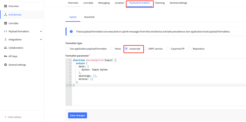
Add the decoder from this link: https://github.com/dragino/dragino-end-node-decoder/tree/main/TrackerD
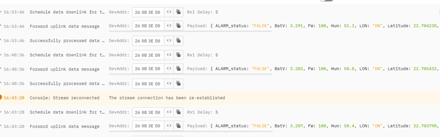
Save the change the uplink message will be parsed. As below:
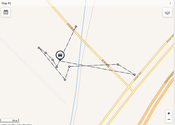
2.5 Integrate with Datacake
After TrackerD sends data to LoRaWAN server such as TTN, use can pass the data to Datacake and plot out, currently only support GPS plot.
Instruction is here: http://wiki.dragino.com/xwiki/bin/view/Main/Notes%20for%20Data%20Cake/#H7.Example--AddTrackerDGPSTrackingInDataCake
2.6 Integrate with Tago
After TrackerD sends data to LoRaWAN server such as TTN, user can pass the data to Datacake and plot out, currently only support GPS plot.
Instruction is here: http://wiki.dragino.com/xwiki/bin/view/Main/Tago.IO/#H3.A0Example-CreateTrackerD2FLGT92positioningwidget
2.7 Integrate with Node-red
1. Install node-red, please refer to the installation method in the link:
http://wiki.dragino.com/xwiki/bin/view/Main/Node-RED/#H1.A0Installation
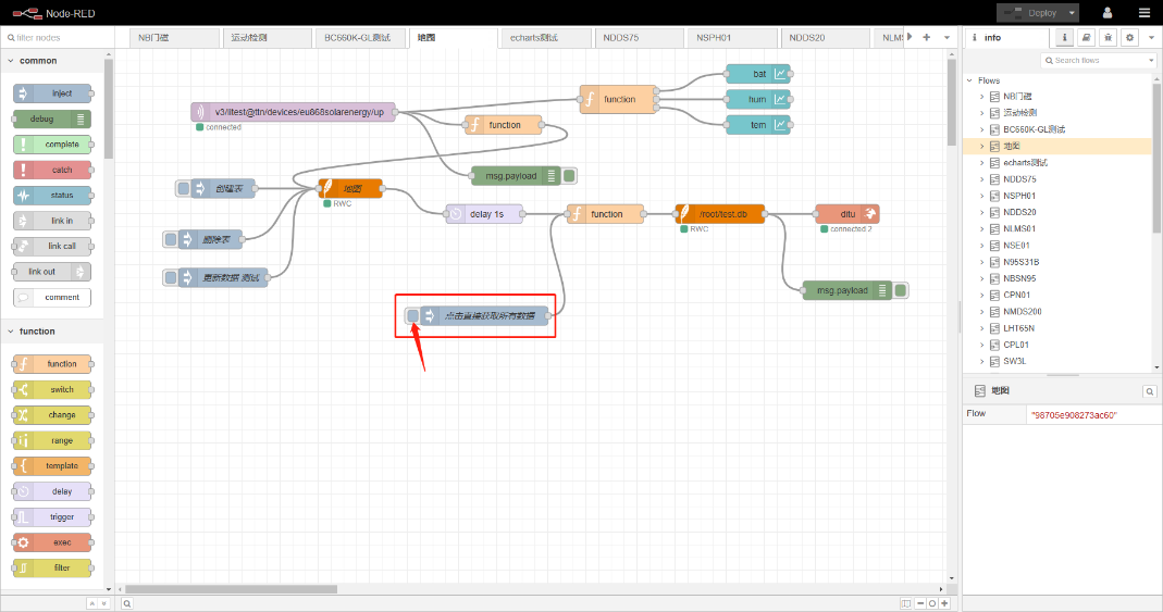
2. Import the created flow template, please refer to the import method in the link:
http://wiki.dragino.com/xwiki/bin/view/Main/Node-RED/#H3.A0Importsampleflow
The address of the flow template: dragino-end-node-decoder/TrackerD.json at main · dragino/dragino-end-node-decoder · GitHub
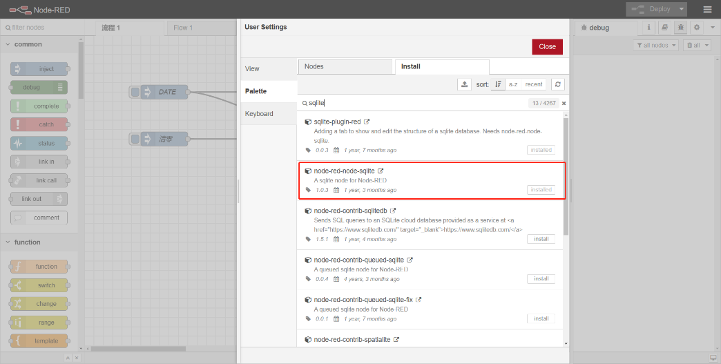
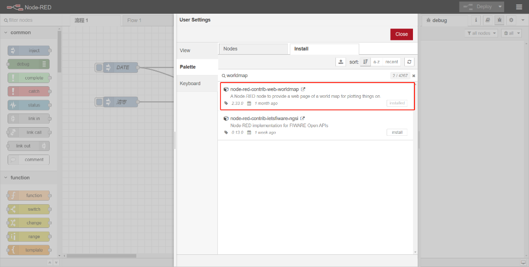
Note: If you are using NODE-RED for the first time, please search and install the two plug-ins in the figure below in node-red to fully use the flow template.
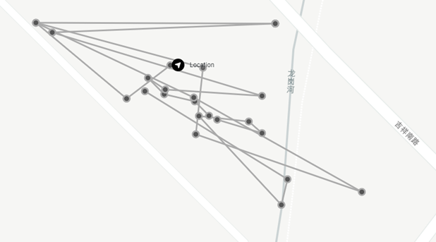
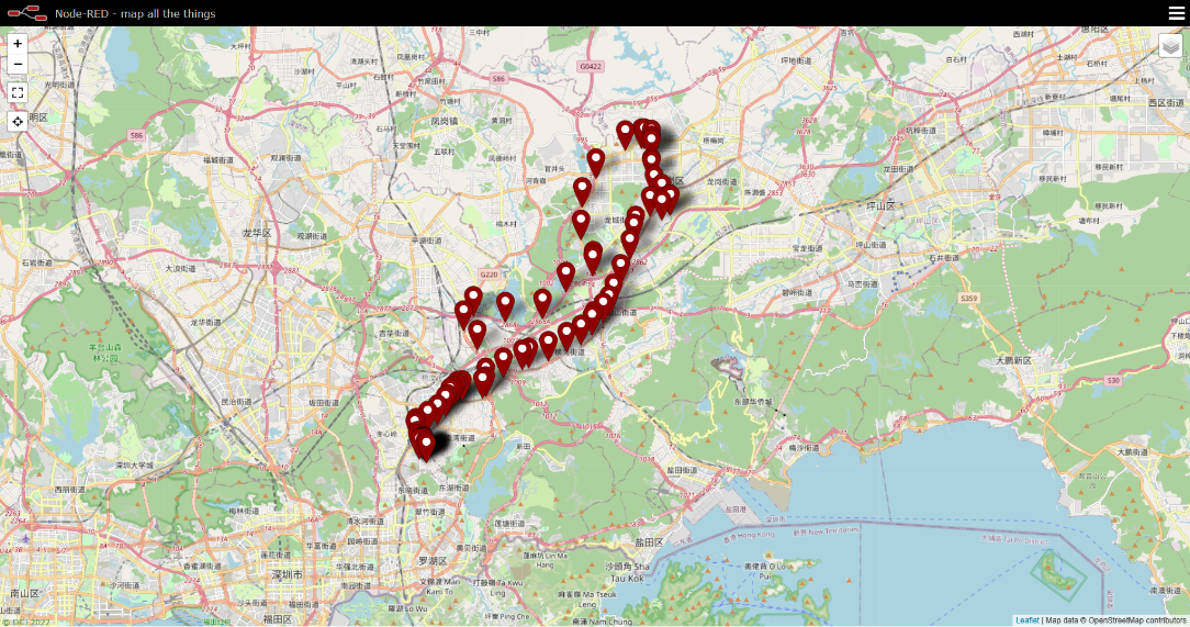
3. Display the map
Enter the link to the map:
Change its suffix to ditu:http://119.91.62.30:1880/ditu/
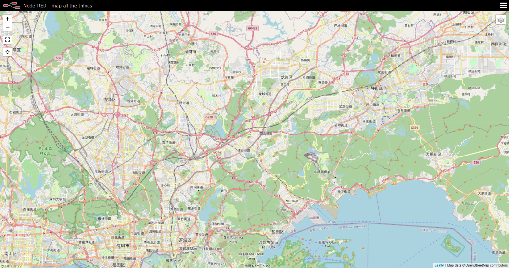
Hit all input in input stream
View map again
2.8 Datalog Feature
total 273 entries,by default,
User can set PNACKMD=1, to enable Datalog feature.
Example use case.
2.9 Alarm Mode
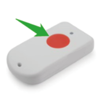
User can push the RED button by more than 5 seconds to enter Alarm Mode. Alarm Mode is used to send SOS info to IoT platform.
Once enter Alarm mode, the GREEN LED will flash 3 times, the buzzer will alarm for 5 seconds, then TrackerD will immediately send a packet without location info and then send a data packet with GPS positioning information. After that, the device will send 60 packets at 1-minute intervals. The Alarm flag in the payload will be set for the next 60 packets unless exits alert mode.
Two ways to exit alarm mode:
- Server sends a downlink command to exit.
- User fast press the RED button 10 times.
When exit alarm mode, RED LED will light up for 5 seconds, indicating that the alarm mode is exited. And the alert flag will be set to false.
2.10 Transport Mode
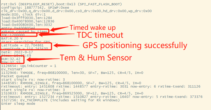
In Transport Mode, TrackerD will check if there is motion (threldhold defined by PT) . If there is no motion, device will send uplinks every 20 minutes (Defined by TDC) . If there is motion, device will send uplink every 5 minutes(defined by MTDC).
When device is set in Transport Mode, it will uplink more frequenctly during moving.
- MTDC defines the Uplink Interval during transportation.
- TDC defines the uplink interval when TrackerD is stactic.
- PT defines the threldhold to detect a motion.
2.11 LED Status
| Event | Action | AT+LON to control on/off |
|---|---|---|
| Power On | BLUE, RED , Green flash once | N/A |
| Join request | Green led fast blink once (200ms) | Yes |
| Join Success | Green led on 5 second | N/A |
| Fixing Location | BLUE blinks 200ms per second | Yes |
| Fixed and uplink | GREEN blinks twice (200ms per blink) | Yes |
| Fail Fix and uplink | RED blinks twice (200ms per blink) | Yes |
| Enter Alarm mode | RED on for 3 seconds | Yes |
| Uplink under Alarm | RED on for 1 second | Yes |
| Exit Alarm | BLUE led on 5 second | Yes |
| Get Downlink | GREEN led on 1 second | Yes |
| Movement Detect | RED led on 500ms | N/A |
2.12 Button Function
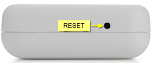
RESET button:
Push this button will reboot the device. Device will exit alarm mode and re-join to LoRaWAN server.
RED button:
| Function | Action | Description |
|---|---|---|
| Send Alarm | Keep Pressing RED button for more than 5 seconds | Enter Alarm Mode. See Alarm Mode |
| Exit Alarm Mode | Fast press the RED button 10 times | Exit Alarm Mode |
| Enter Deep Sleep Mode | Press and hold the button for 10 seconds, then quickly press the device 3 times to enter deep sleep | This is the mode ship out from factory. CPU will be complete in sleep mode and no LoRa activity, only use before deploy. |
2.13 USB Port Function
The USB interface of TrackerD has below functions:
- Power on the device
- Recharge the battery
- Configure Device
- Upgrade Firmware
2.14 Sleep Mode
Sleep Mode: To prevent accidental touch of the red button during transportation or assembly, so the peripherals of the device are turned off and enter deep sleep.
In SLEEP mode, you need to reset by reset button.
Use the AT+SLEEP command to put the device into sleep.
3. Configure TrackerD via AT command or LoRaWAN downlink
User can configure TrackerD via AT Command or LoRaWAN Downlink.
LoRaWAN Downlink instruction for different platforms: IoT LoRaWAN Server
3.1 Access AT Command
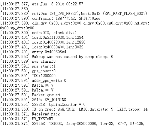
TrackerD supports the AT command set in stock firmware. User can connect to TrackerD with TYPE-C cable to use AT commands as shown below.
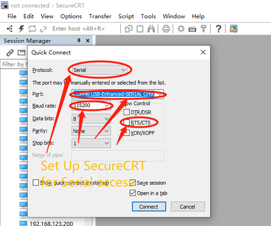
In PC, User needs to set serial tool baud rate to 115200 to access serial console for TrackerD. TrackerD will output system info once power on and user will be able to send AT commands:
3.2 Command Set
3.2.1 Set Transmit Interval
Set device uplink interval.
- AT Command:
AT+TDC=xxx
Example: AT+TDC=300000. Means set interval to 5 minutes(300 seconds)
- Downlink Payload (prefix 0x01):
0x01 00 01 2C // Same as AT+TDC=300000
3.2.2 Set Alarm Packet transmission interval
Set alarm packet transmit interval
- AT Command:
AT+ATDC=xx.
Example: AT+ATDC=60000 --> Set Alarm Packet Interval to 60 seconds. TrackerD will send every 60 seconds in Alarm mode, Default Value: 60000
- Downlink Payload (prefix 0xB1):
0xB1 00 00 3C // Same as AT+ATDC=60000
3.2.3 Set Transport Mode Packet transmission interval
Set Transport Mode packet transmit interval
- AT Command:
AT+MTDC=xx.
Example: AT+MTDC=300000 --> Set Transport Mode Packet Interval to 300 seconds. TrackerD will send every 300 seconds in Transport mode, Default Value: 300000
- Downlink Payload (prefix 0x03):
0x03 00 01 2C // Same as AT+MTDC=300000
3.2.4 Exit Alarm
Server send downlink command to exit Alarm mode
- AT Command: No AT Command
- Downlink Payload (prefix 0x02):
0x02 01 // Exit Alarm Mode
3.2.5 Disable/Enable LED flash and buzzer
Disable/Enable LED for position, downlink and uplink
- AT Command:
AT+LON=xx. (Disable (0), Enable (1), default:1)
Example: AT+LON=0 --> Disable LED for position, downlink and uplink.
- Downlink Payload (prefix 0xAE):
0xAE 00 // Same as AT+LON=0
3.2.6 Disable/Enable Transport Mode
Users can use this feature to enable/disable Transport Mode.
- AT Command:
AT+INTWK=xx. (Disable (0), Enable (1), default:0)
Example: AT+INTWK=1 --> Enable Transport Mode.
- Downlink Payload (prefix 0xAF):
0xAF 01 // Same as AT+INTWK=1
3.2.7 Set Positioning Mode
SMOD define how TrackerD scan and uplink data:
- AT Command:
AT+SMOD=aa,bb,cc
aa:
- 1: GPS ONLY(Factory Settings): Only get and uplink GPS location info.
- 2: BLE or WiFi ONLY: Only obtain iBeacon info via BLE and uplink or obtain WiFi ssid info via WiFi and uplink. Design for Indoor tracking.
- 3: GPS/BLE Hybrid: Combination for Indoor and Outdoor tracking.Devices will try to search BLE iBeacon first. If device can't find the iBeacon, it will use GPS for positioning.
bb:
- 0 : GPS+ BAT+ State+Tem&Hum
- 1 : GPS +BAT State
cc:
- 1 : (iBeacon)UUID+ Major + Minor+Power+Rssi+BAT+State
- 2 : (WiFi)SSID+Rssi+BAT+State (V1.4.1 Version support this function later)
Example:
AT+SMOD=1,0,0 --> GPS+ BAT+ State+Tem&Hum
AT+SMOD=1,1,0 --> GPS +BAT State
AT+SMOD=2,0,1 --> (iBeacon)UUID+ Major + Minor+Power+Rssi+BAT+State
AT+SMOD=2,0,2 --> (WiFi)SSID+Rssi+BAT+State
AT+SMOD=2,0,3 --> (iBeacon) (Major + Minor+Rssi)+(Major + Minor+Rssi)+...(Maximum forty group)...+BAT+State
- Downlink Payload (prefix 0xA5):
0xA5 01 00 00 // Same as AT+SMOD=1,0,0
3.2.8 Set MAX GPS position time
Set max positioning time, default is 150 seconds. TrackerD will try to get location info within this period. If fail to get position data within this time, TrackerD will use 000000 for latitude and longitude.
If AT+FTIME=0. The GPS module will be always powered and positioning. This will highly increase the power consumption (up to 50mA). When AT+FTIME=0, it will improve fix accuracy and shorten the acquire time for next uplink.
- AT Command:
AT+FTIME=xx --> Set to use xx as max fix time.
Example: AT+FTIME=150
- Downlink Payload (prefix 0xAA):
0xAA 00 96 // Set AT+FTIME=150
3.2.9 Set PDOP value for GPS fix accuracy
PDOP(Position Dilution of Precision) filter, TrackerD will only accept GPS data with a lower PDOP value than pre-configure PDOP value. If device can't get a valid GPS packet within FTIME timeout, it will use the GPS data with lowest PDOP value to server.
A GPS packet with lower PDOP has higher accuracy. PDOP default value is 2.0
- AT Command:
AT+PDOP=2.5 --> Set PDOP to 2.5
- Downlink Payload (prefix 0xAD):
0xAD 00 0A // Set AT+PDOP=1 (0x0A / 10 =1)
0xAD 00 19 // Set AT+PDOP=2.5 (0x19 / 10 =2.5)
0xAD 00 46 // Set AT+PDOP=7 (0x46 / 10 =7)
3.2.10 Disable/Enable the confirmation mode
- AT Command:
AT+CFM=xx
Example:
AT+CFM=0 --> Disable confirmation
AT+CFM=1 --> Enable confirmation
- Downlink Payload (prefix 0x05):
0x05 01 // Same as AT+CFM=1
3.2.11 Auto Send None-ACK messages
TrackerD will wait for ACK for each uplink, If TrackerD doesn't get ACK from the IoT server, it will consider the message doesn't arrive server and store it. TrackerD keeps sending messages in normal periodically. Once TrackerD gets ACK from a server, it will consider the network is ok and start to send the not-arrive message.
- AT Command: AT+PNACKMD
The default factory setting is 0.
Command Example Function Response:
AT+PNACKMD=1 // Poll None-ACK message OK
- Downlink Command: 0x34
Example: 0x34 01 // Same as AT+PNACKMD=1
3.2.12 Set BLEMASK to filter BLE iBeacon
BLEMASK is to filter the unwanted BLE iBeacons during scan. For example, if BLEMASK is 123456. TrackerD will only uplink UUID info which includes 123456. It will ignore all other iBeacons which doesn’t contact 123456 in the UUID.
Note: BLEMASK range is 6 ~ 10 bytes. If AT+BLEMASK < 6 bytes, BLEMASK will be disabled.
AT Command:
AT+BLEMASK=123456 // Set BLEMASK = 123456
AT+BLEMASK=0 // disable BLEMASK
Downlink Payload: (Prefix : 0xB2)(Since firmware 1.4.1)
Example: 0xB2 01 02 03 04 05 06 // Set BLEMASK to 123456
3.2.13 Set WiFIMASK to filter WiFi SSID(Since firmware 1.4.1)
WiFiMASK is to filter the unwanted WiFi SSID during scan. For example, if WiFiMASK is 123456. TrackerD will only uplink SSID info which includes 123456 as prefix. It will ignore all other WiFi which doesn’t contact 123456 in the SSID.
Note: WiFiMASK range is 6 ~ 10 bytes. If AT+ WiFiMASK < 6 bytes, WiFiMASK will be disabled.
AT Command:
AT+WiFiMASK=123456 // Set WiFiMASK = 123456
AT+WiFiMASK=0 // disable WiFiMASK
Downlink Payload: (Prefix : 0xB3)(Since firmware 1.4.1)
Example: 0xB3 01 02 03 04 05 06 // Set WiFiMASK to 123456
3.2.14 Disable/Enable Information printing(Since firmware 1.4.1)
Users can use this feature to enable/disable Information printing.
AT Command:
AT+SHOWID=XX // (Disable (0), Enable (1), default:0)
Example: AT+SHOWID=1 --> Enable Information printing.
3.2.15 Get or Set Eight Channels Mode, only for us915, AU915(Since firmware 1.4.1)
The Channels Mode in the LORAWAN LMIC library is from 0 ~ 7. When CHE = 8, 72 channels will be accessible to the network.
AT Command:
AT+CHE=1 // set one channels mode
Downlink Payload:0X24
Example: 0x24 01 // Same as AT+CHE=1
3.2.16 Get or Set Threshold for motion detect(Since firmware 1.4.3)
User can set the motion detect thredhold for transportation mode. The smaller the value, the more sensitivity to trigger a motion event.
AT Command:
AT+PT=xx
Example:
AT+PT=14 --> Set to detect car motion.
AT+PT=41 --> set to detect walk motion.
Downlink Payload:0xB4
0xB4 14 // Same as AT+PT=14
3.2.17 Set AT command window time(Since firmware 1.4.5)
AT command window time setting, customers can set the required time according to their own operation mode.The unit is second.
AT Command:
AT+ATST=XX
Example:
AT+ATST=15 --> Set the time to 15 seconds
Downlink Payload:0XB5
0xB5 0F // Same as AT+ATST=15
3.2.18 Set the stepmeter mode(Since firmware 1.4.5)
After setting the step counting mode, it cannot be interrupted by motion. This mode is very power consuming. Used on some special occasions.
AT Command:
AT+PM=xx
Example:
AT+PM=1 --> Turn on step counting mode
AT+PM=0 --> Turn OFF step counting mode
Downlink Payload:0XB6
0xB6 01 // Same as AT+PM=1
3.2.19 Set down the decline detection mode(Since firmware 1.4.5)
This mode is used in conjunction with AT+PT(The recommended threshold is between 50 and 70, you need to set it according to the environment yourself). This function is used in hospitals, nursing homes, nursing homes and other places to prevent the elderly and patients from falling. No one knows.
AT Command:
AT+FD=xx
Example:
AT+FD=1 --> Turn on the Fall detection
AT+FD=0 --> Turn OFF the Fall detection
Downlink Payload:0XB7
0xB7 01 // Same as AT+FD=1
3.2.20 Disable/Enable buzzer(Since firmware 1.4.6)
Disable/Enable buzzer for Alarm, downlink and uplink
AT Command:
AT+BEEP=XX
Example:
AT+BEEP=1 --> Turn on the buzzer
AT+BEEP=0 --> Turn OFF the buzzer
Downlink Payload:0XB9
0xB9 01 // Same as AT+BEEP=1
3.2.21 Set long press time(Since firmware 1.4.6)
When using the red button Changan to alarm, press and hold the time to set 0~10 seconds(The default value is 5 seconds), which is convenient for use scenarios.
AT Command:
AT+EAT=XX
Example:
AT+EAT=2 --> Set the long press time to 2s
Downlink Payload: 0XBA
0xBA 02 // Same as AT+EAT=2
3.2.22 Set the Bluetooth scan time(Since firmware 1.5.1)
Use this command to set the Bluetooth scan time. Default is 5s, value range: 1~255.
AT Command:
AT+BTDC=XX
Example:
AT+BTDC=5 --> Set the Bluetooth scan time to 5s
Downlink Payload:
No downlink
3.2.23 Conversion of TrackerD and TrackerD-LS(Since firmware 1.4.9)
They use the same source code and can be converted using the AT command below
AT Command:
AT+DEVICE=22
Example:
AT+DEVICE=22 --> Set to TrackerD-LS
AT+DEVICE=13 --> Set to TrackerD
4. Setting for Different Scenarios
5. Upload Firmware
5.1 Firmware Change Log
5.2 How to upgrade firmware
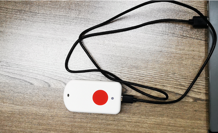
User can use the TrackerD's USB port to upgrade firmware into it. The hardware connection for upgrade firmware is as below:
Step1: Connect TrackerD and PC via USB cable shipped with TrackerD.
Step2: Install CH9102 driver in the PC.
After installation of the driver and plug in TrackerD, user should be able to see com port in PC's device manager.
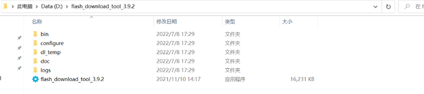
Step3: Download and Install Flash Tool: Tools | Espressif Systems
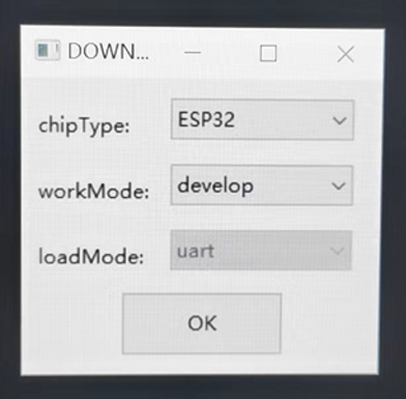
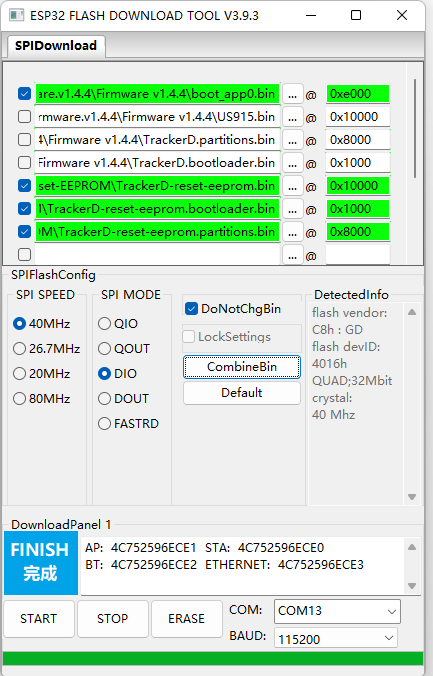
Step4: Run Flash Download Tool and configure chip type to ESP32
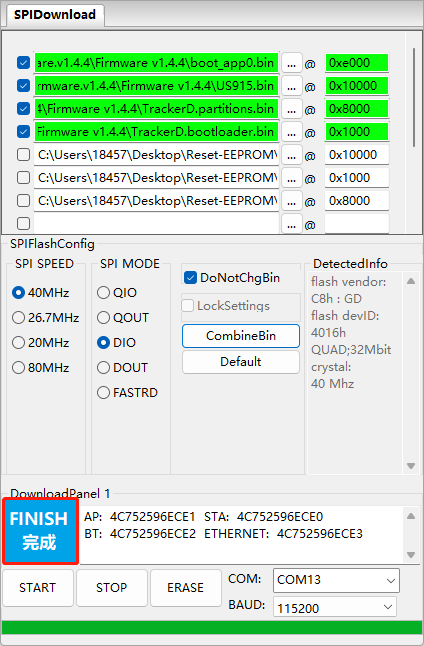
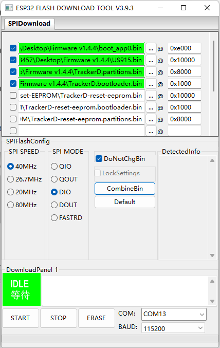
Step5: Select the firmware file (.bin format), com port and proper SPI configure. Clink Start. Bin file location:
https://github.com/dragino/TrackerD/releases
Users need to use below files:
boot_app0.bin @0e000
US915.bin @ 0x10000(Select the bin file of the frequency band you need)

After upgrade finish, it will show finish as below:
6. Developer Guide
6.1 Compile Source Code
6.1.1 Set up ARDUINO compile environment
- Download the latest Arduino software (IDE) from the Arduino official website: https://www.arduino.cc/en/Main/Software
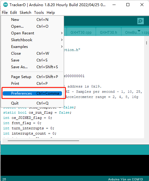
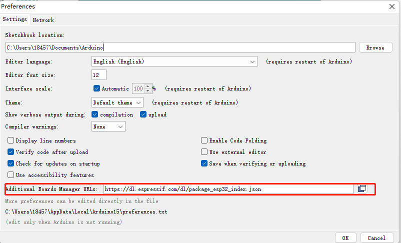
Install IDE on PC, open and click File --> Preference, add the following URL: https://dl.espressif.com/dl/package_esp32_index.json
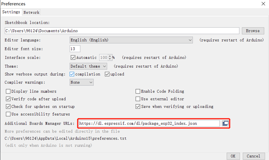
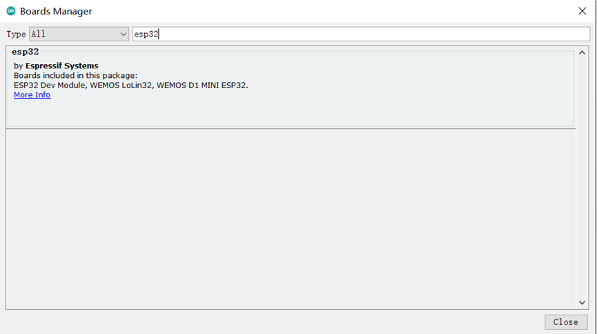
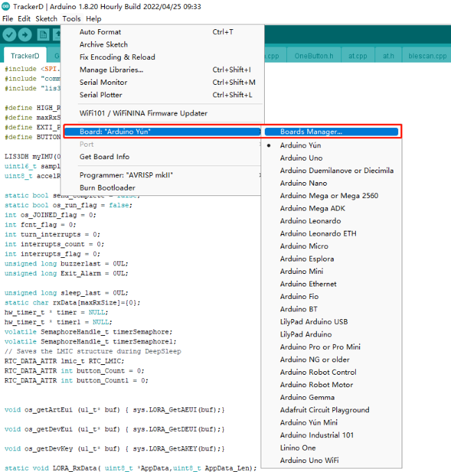
- Go to tools --> Boards --> Boards Manager, find the esp32 information and install it.
6.1.2 Build the development environment
1. Download and install arduino IDE
https://www.arduino.cn/thread-5838-1-1.html
2. Download the ESP32 development package in the arduino IDE
Input: https://dl.espressif.com/dl/package_esp32_index.json
Restart the IDE after the addition is complete, then:
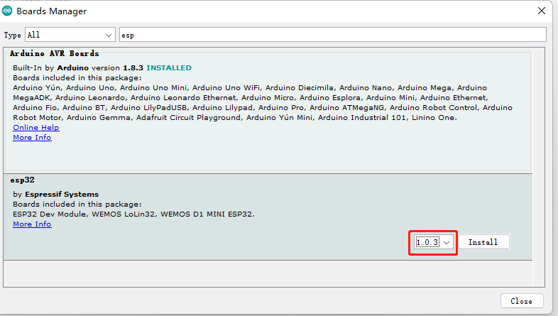
Note: Currently version 1.04 is almost impossible to download, you can choose version 1.03.
Don't quit halfway.~! If you quit halfway, there is a high probability that it will freeze, and you will need to download again next time. (If you click to continue downloading, an error will be reported after completion)
Then enter a long waiting process. If you don't want to wait, you can go to the Internet to download directly, and then import:
Methods as below:
1. Download: https://github.com/dragino/TrackerD/releases/tag/v1.4.4
2. Find the arduino installation path, hardware → create a new espressif folder → create a new esp32 folder, unzip the compressed package here.
Find the path of SP32 installation, find the file as shown in Figure 1, and change the SPI pin to the shown in Figure 2.
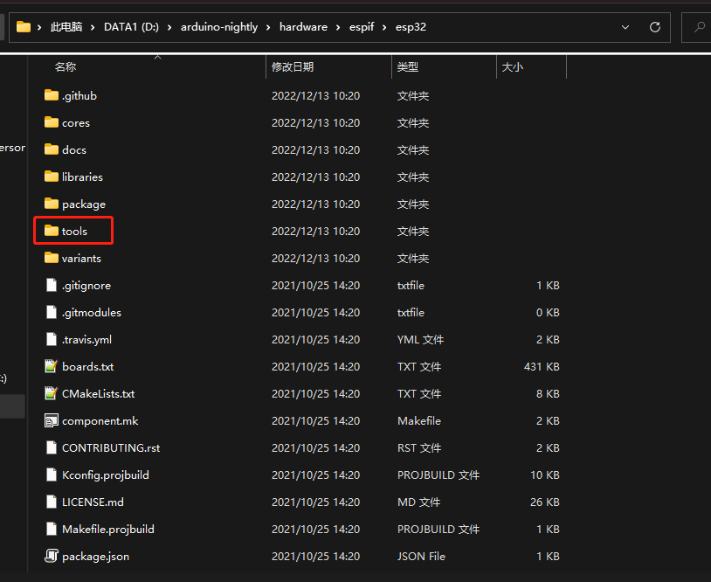
3. Find tools→get.exe in the decompressed file and run it (it will close automatically after completion)
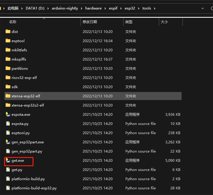
Note: This step requires a python environment
Either way, in the end:
The final effect is to open the arduino and you can see the esp32
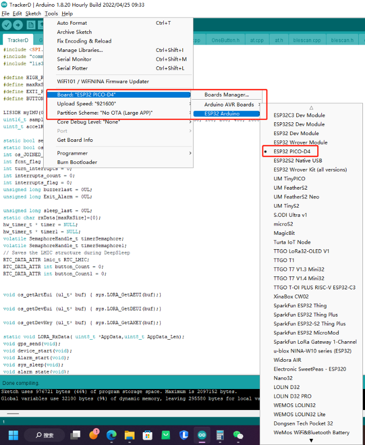
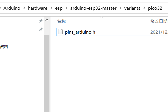
Figure1
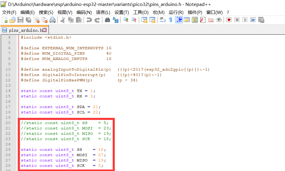
Figure2
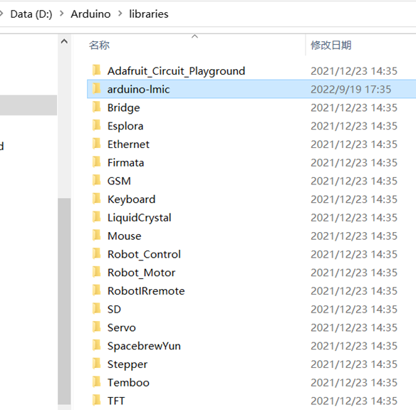
- Download the latest TrackerD from the dragino github: https://github.com/dragino/TrackerD
Put the Library in the TrackerD directory into the libraries file in the Arduino directory:
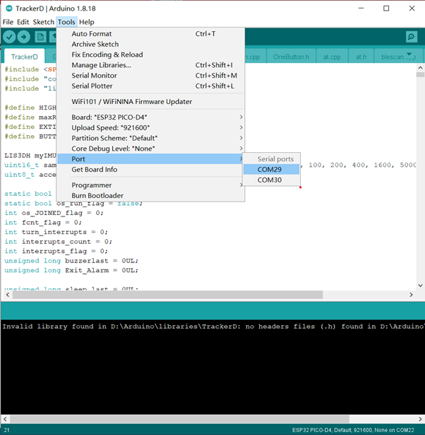
6.2 Source Code
- Open the example in the TrackerD file, please select the correct port in the IDE, as shown below:
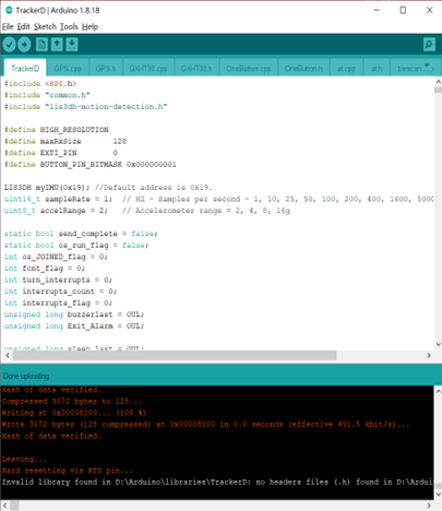
- Click to upload
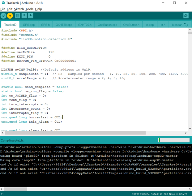
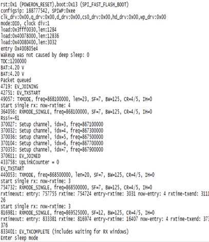
- Check the result, if the upload is successful, as shown below, open the serial port to view the data
7. FAQ
7.1 How to change the LoRa Frequency Bands/Region?
User can follow the introduction for how to upgrade image. When download the images, choose the required image file for download.
7.2 What is the pin mapping for the USB program cable?
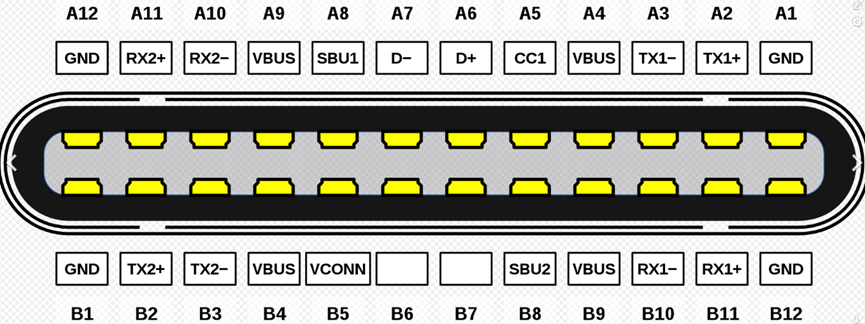
| Pin | Color | USB Pin |
|---|---|---|
| A4,B4,A9,B9 | Red | VCC |
| A7,B7 | White | D- (N/A) |
| A6,B6 | Green | D+(N/A) |
| A1,B1,A12,B12 | Black | GND |
| A5 | Purple | MTDC/GOIO13 |
| B5 | Blue | MTDC/GPIO12 |
| A8 | Yellow | MTMS/GPIO14 |
| B8 | Grey | MTDO/GPIO15 |
7.3 Notes on using different serial port tools for TrackerD
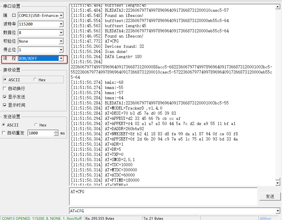
7.3.1 Serial port utility
Serial port utility requires you to automatically add data streams.
Need to adjust the data stream to RTS/CTS on physical restart.
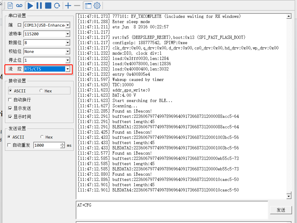
When using AT commands, the data flow needs to be adjusted to XON/XOFF
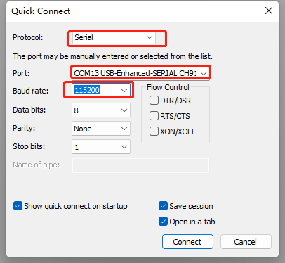
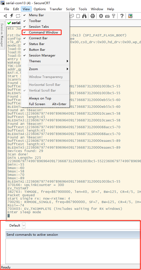
7.3.2 SecureCRT
The default command window of SecureCRT is not displayed. Entering a command requires a complete input of the entire command. You can open the command window in the view.
7.3.3 PUTTY
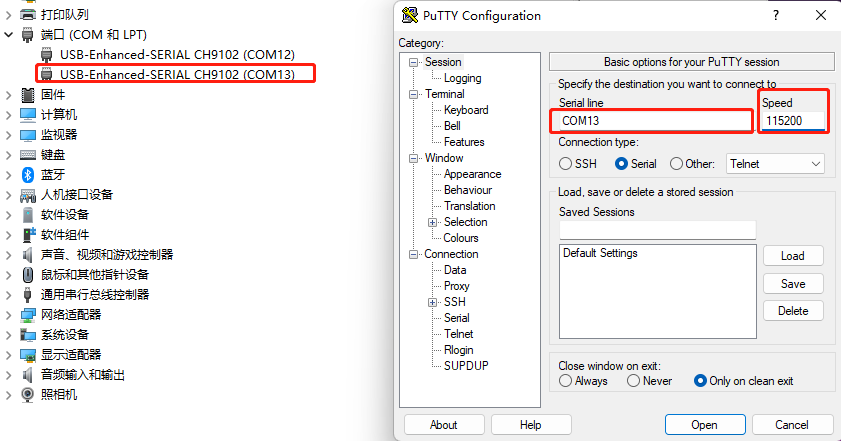
Since putty does not have a command window, you need to fill in the complete command externally, and then copy it to putty.The information copied outside can be pasted by right-clicking the mouse in putty.
7.4 How to modify source code to compile different frequency band bin file?
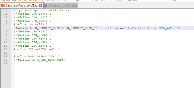
1. When compiling the frequency band, you need to find LMIC_PROJECT_CONFIG.H file.
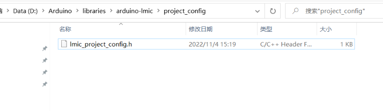
2. Open LMIC_PROJECT_CONFIG.H, find the corresponding macro definition and open it(AS923_2,AS923_3,AS923_4 except).
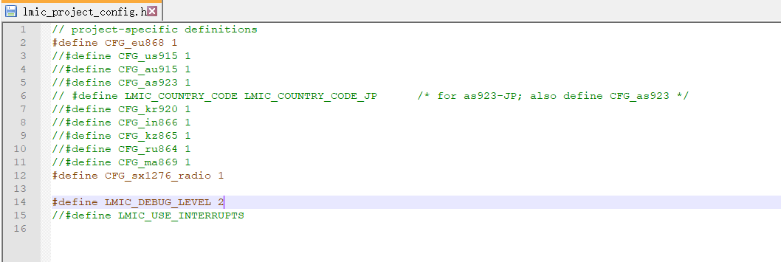
3. Compile the AS923_JP band, please refer to the intention shown
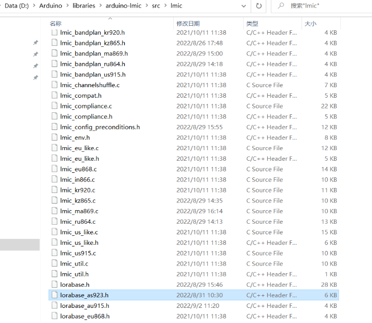
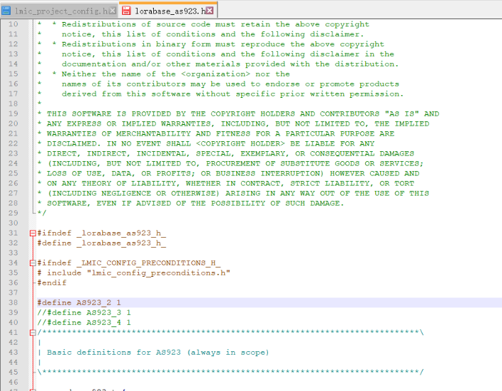
4. In other frequency bands in AS923, you need to find Lorabase_as923.H, path arduino-lmic \ src \ lmic, as shown in the figure below.
7.5 Are there example python example for BLE Indoor Positioning?
Operating instructions for BLE indoor positioning
7.6 Can alert mode and transport mode be used together?
Yes, you can also press the panic button to sound the alarm if set to transport mode
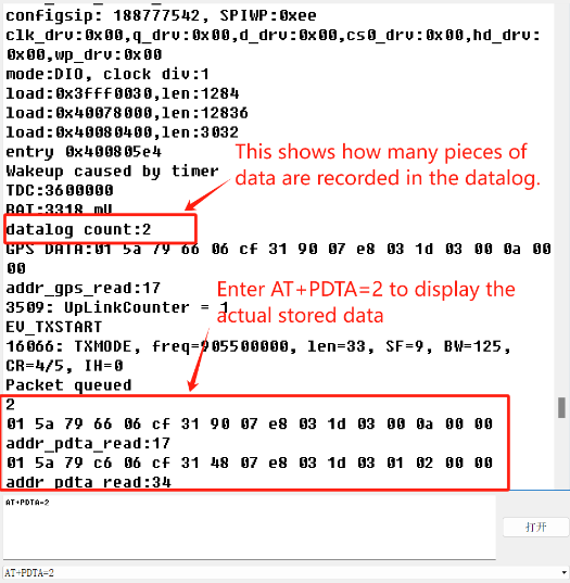
7.7 Can i get the datalog record from console?
Since firmware TrackerD-v1.4.9, User is able to get the datalog record from console as well.
7.8 FAQs for upgrading to version 1.4.9 or later
1.The device does not display version information or indicates low battery
Please set the device type
AT+DEVICE=13-->TrackerD
AT+DEVICE=22->TrackerD-LS
2.Unable to control the red button on trackerD
Due to the integration of the old and new versions of the software, we have added a judgment condition to the software. Sometimes it is necessary to judge the old and new versions and then the red button function can be used normally.
- For V1.4.9 and earlier versions, you need to set an 8-bit DADDR equal to or less than 01880788.
Example:
AT+DADDR=01880688
- For new versions after V1.4.9, the user needs to set an 8-bit DADDR greater than 01880788.
Example:
AT+DADDR=01880789
8 Trouble Shooting
8.1 TDC is changed to 4294947296 and cause no uplink.
Before firmware v1.4.0: When the Transport Mode is enabled (AT+INTWK=1), the TDC needs to be greater than MTDC, otherwise, TDC setting will because 4294947296 after wakre up from motion. This bug is fixed in firmware v1.4.1
8.2 Device not able get AT Command or show output after wake up from deep sleep mode
ESP32 is not able to accept the Interrupt from UART after wake up from deep sleep mode. User need to press the button (one click) and trackerD will be able to accept UART command, it there is no action in UART for 15 seconds. it will go to deep sleep mode.
8.3 Problem after Upgrading Firmware
8.3.1 "rst: (0x3 SW_RESET)" and Continue Restart after upgrading
Error Output
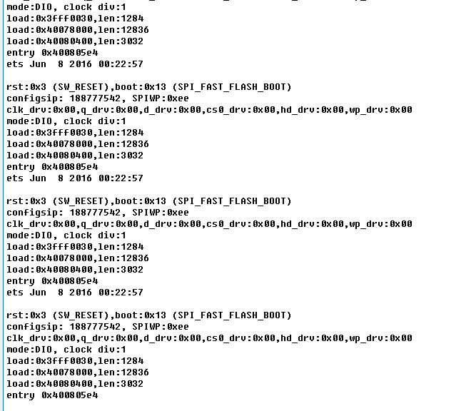
Some partition is missed during upgrade, please upgrade below four files as example:
8.3.2 TrackerD's led light is always GREEN on after upgrading
It is because the partitions are different when upgrading versions above 1.4.1, and a new partition file needs to be added. Please refer to the operation steps in chapter 8.3.1
8.3.3 "flash read err" after upgrade firmware
Error shows below, user might erase the entire flash include u-boot partition which cause this issue.
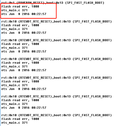
User need to upgrade again with below four files to solve this issue.

Figure 2
8.3.4 "Device Key become ff ff ff ff ff ff ff ff " after upgrade firmware
User might erase the entire flash include keys and default settings which cause this issue.
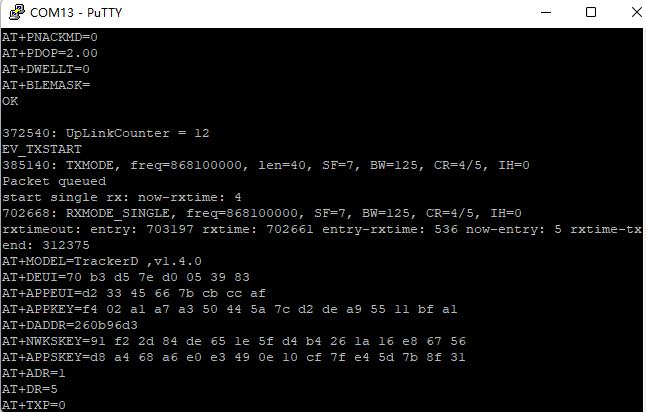
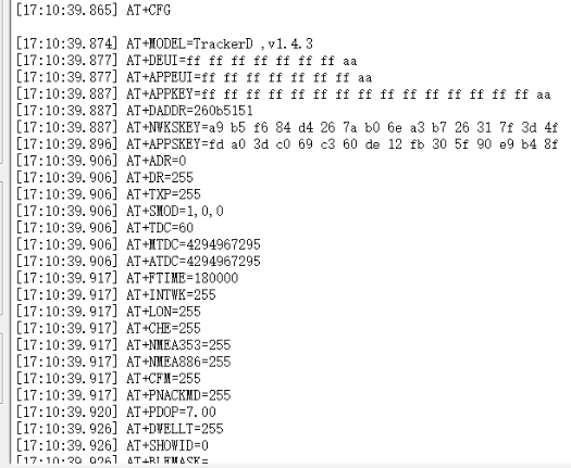
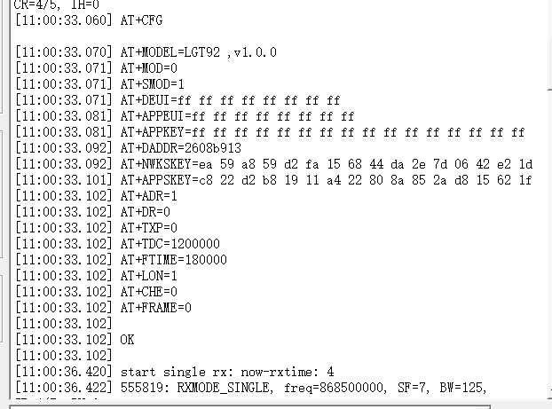
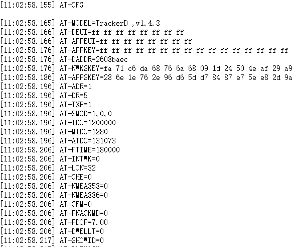
After the upgrade is completed, enter AT+CFG as shown in the figure below.
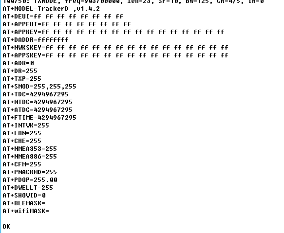
Please AT+FDR which will reset all settings to factory settings. , and then input the following keys by the information on the label.
After AT+FDR. please set
- AT+PDOP=7
- AT+FTIME=180000
Example:
AT+PDOP=7.00
AT+FTIME=180
AT+DEUI=70B3D57ED0053981
AT+APPEUI=D23345667BCBCCAF
AT+APPKEY=F402A1A7A350445A7CD2DEA95511BFA1
AT+DADDR=260b4dce ( no need for OTAA)
AT+NWKSKEY=71cb7672441f573a53d4f34d307fc61d ( no need for OTAA)
AT+APPSKEY=dacce2299ecd97a73ee3f80b5a46a559 ( no need for OTAA)
8.4 When positioning, it will restart or the PDOP setting is unsuccessful
Please download version 1.4.2 again
8.5 How to deal with unsuccessful GPS positioning?
1) Make Sure the device is in Open Area where can see the sky.
2) Set PDOP to a higher value.
- AT+PDOP=2 (can be positioned precisely.)
- AT+PDOP=7 (Quickly locate in open spaces)
- AT+PDOP=14.7 (Positioning can be acquired in complex environments)
Please refer to this link on how to set up PDOP
8.6 When upgrading the firmware, the data is not completely erased, and the information does not return to normal after multiple resets
When upgrading, use the erase button to upgrade

The parameters are displayed abnormally and cannot be fixed using AT+FDR
Please upgrade these four files,link(The boot_app0 file is in the version folder you need)
Reboot information after upgrade
Use AT+FDR command to reset and then use AT+CFG to check whether the configuration is back to normal
After the parameters return to normal, upgrade to the version you need again

At this point, the parameters return to normal after running AT+FDR again
8.7 If you encounter the following problems, please upgrade to the latest version
1. Press and hold the red button (more than 5 seconds), and the device and server do not respond.
2. Send some commands through the serial port to prompt an error (Example:AT+SMOD=1,0,1)
8.8 Why when using some serial consoles, only inputting the first string port console will return "error"?
Need to enter the entire command at once, not a single character.
User can open a command window or copy the entire command to the serial console.
8.9 When the device is connected to the serial port, it cannot send Uplink, the light color is abnormal, and it does not respond to commands.
ESP32 hardware is affected by the flow control of the serial port control program, which causes abnormal phenomena.
Please do not select flow control when using the serial port tool.
Please refer to this link to use the serial port tool
9. Order Info
Part Number: TrackerD-XXX
XXX: The default frequency band
- EU433: Default frequency band EU433
- EU868: Default frequency band EU868
- IN865: Default frequency band IN865
- KR920: Default frequency band KR920
- AS923: Default frequency band AS923
- AU915: Default frequency band AU915
- US915: Default frequency band US915
10. Packing Info
Package Includes:
- TrackerD LoRaWAN GPS/BLE Tracker x 1
- USB recharge & program cable x 1
Dimensions and Weight:
- Device Size: 85 x 48 x 15 mm
- Weight: 50g
11. Support
- Support is provided Monday to Friday, from 09:00 to 18:00 GMT+8. Due to different timezones we cannot offer live support. However, your questions will be answered as soon as possible in the before-mentioned schedule.
- Provide as much information as possible regarding your enquiry (product models, accurately describe your problem and steps to replicate it etc) and send a mail to support@dragino.com.