1. point to point
1.1 Overview
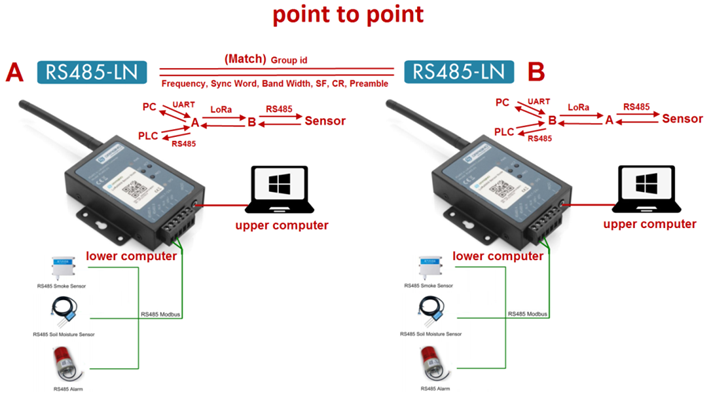
1.2 Configure
A's configuration: B's configuration:
AT+GROUPMOD=0 AT+GROUPMOD=0
AT+GROUPID=12345678 AT+GROUPID=12345678
AT+TXCHS=868700000 AT+TXCHS=869000000
AT+RXCHS=869000000 AT+RXCHS=868700000
AT+CFGDEV=01 03 00 00 00 04,1 AT+CFGDEV=01 03 00 00 00 02,1
or or
AT+COMMAND=01 03 00 00 00 04,1 AT+COMMAND=01 03 00 00 00 02,1
1.3 Serial port display
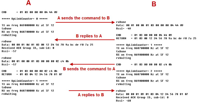
A sends a command to B to query B's RS485 sensor data and display it on A's upper computer.
Similarly, B sends a command to A to query A's RS485 sensor data and display it on B's upper computer.

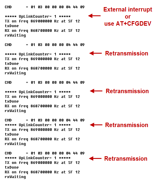
If the sender does not get the ACK reply from the receiver, it will retransmit up to 4 times, each interval is 10 seconds, and the UplinkCounter of the retransmission will not increase. (Retransmission only occurs when using the AT+CFGDEV command or triggering an external interrupt)
2.2 Point To Mult-Point
2.2.1 Overview
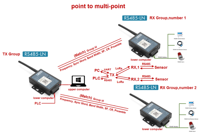
2.2.2 Configure
Configuration of the TX group:
AT+GROUPMOD=0,2
AT+GROUPID=12345678
AT+TXCHS=868700000
AT+RXCHS=869000000
AT+CFGDEV=01 03 00 00 00 02,1
or
AT+COMMAND=01 03 00 00 00 02,1
Configuration for RX group number 1:
AT+GROUPMOD=1,1
AT+GROUPID=12345678
AT+TXCHS=869000000
AT+RXCHS=868700000
Configuration for RX group number 2:
AT+GROUPMOD=1,2
AT+GROUPID=12345678
AT+TXCHS=869000000
AT+RXCHS=868700000
2.2.3 Serial port display
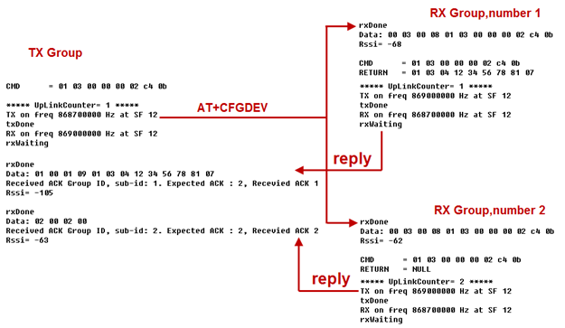
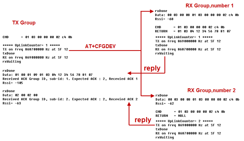
The TX group sends broadcast data to the RX group. After the RX group receives the data, it will reply to the TX group in order from small to large.
If the sender does not get the ACK reply from the receiver, it will retransmit up to 4 times, each interval is 30 seconds, and the UplinkCounter of the retransmission will not increase.(Retransmission only occurs when using the AT+CFGDEV command or triggering an external interrupt)
2.3 AT command
ATZ :Trig a reset of the MCU
AT+FDR :Reset Parameters to Factory Default, Keys Reserve
AT+FCU :Get or Set the Frame Counter Uplink
AT+FCD :Get or Set the Frame Counter Downlink
AT+TXP :Get or Set the transmit power, the maximum is 20dBm (default is 14dBm)
AT+SYNC :Get or Set the Sync word [1:0x34,0:0x12] (default is 1)
AT+PMB :Get or Set the preamble (default:8)
AT+TXCHS :Get or Set the transmit frequency of TX (default:868700000)
AT+TXSF :Get or Set the spreading factor of TX (7 to 12) (default:12)
AT+RXCHS :Get or Set the transmit frequency of RX (default:869000000)
AT+RXSF :Get or Set the spreading factor of RX (7 to 12) (default:12)
AT+BW :Get or Set the bandwidth [0:125khz,1:250khz,2:500khz] (default:0)
AT+CR :Get or Set the coding rate [1: 4/5, 2: 4/6, 3: 4/7, 4: 4/8] (default:1)
AT+TDC :Get or set the application data transmission interval in ms(default 10 minutes)
AT+VER :get firmware version number
AT+SEND :Set Custom sent hex data
AT+GROUPMOD :Set or Get the grouping mode of the device (default: 0)
AT+GROUPID : Set or Get the password for matching between TX group and RX group, which can be composed of numbers or characters (default: 12345678)
ATZ : Trig a reset of the MCU
AT+FDR : Reset Parameters to Factory Default, Keys Reserve
AT+FCU : Get or Set the Frame Counter Uplink
AT+FCD : Get or Set the Frame Counter Downlink
AT+TXP : Get or Set the transmit power, the maximum is 20dBm (default is 14dBm)
AT+SYNC : Get or Set the Sync word [1:0x34,0:0x12] (default is 1)
AT+PMB : Get or Set the preamble (default:8)
AT+TXCHS : Get or Set the transmit frequency of TX (default:868700000)
AT+TXSF : Get or Set the spreading factor of TX (7 to 12) (default:12)
AT+RXCHS : Get or Set the transmit frequency of RX (default:869000000)
AT+RXSF : Get or Set the spreading factor of RX (7 to 12) (default:12)
AT+BW : Get or Set the bandwidth [0:125khz,1:250khz,2:500khz] (default:0)
AT+CR : Get or Set the coding rate [1: 4/5, 2: 4/6, 3: 4/7, 4: 4/8] (default:1)
AT+TDC : Get or set the application data transmission interval in ms(default 10 minutes)
AT+VER : Get firmware version number
AT+SEND : Set Custom sent hex data
AT+GROUPMOD : Set or Get the grouping mode of the device (default: 0)
AT+GROUPID : Set or Get the password for matching between TX group and RX group, which can be composed of numbers or characters (default: 12345678)
AT+INTMOD : Get or Set the trigger interrupt mode
AT+BAUDR : Get or set the baud rate of rs485. (default: 9600)
AT+DATABIT : Get or Set databit(7:7 bits,8:8 bits) of rs485 (default: 8)
AT+PARITY : Get or Set parity(0:none,1:odd,2:even) of rs485(default: 0)
AT+STOPBIT : Get or Set stopbit(0:1 bit,1:1.5 bit,2:2 bit) of rs485(default: 0)
AT+CMDDL : Get or Set the delay waiting time after receiving RS485 command (default: 400)
AT+CRCCHECK : Get or set to receive and verify RS485 sensor data (0: Disable,1:CRC16_MODBUS) (default: 1)
AT+SCHEDULE : Each TDC sends command data to the receiver.
AT+CFGDEV : Instantly send RS485 commands to the receiver.
AT+RS485 : Send commands to the local RS485 device.
AT+MOD : Get or set the host send mode.(default: 0)
Example 1:
AT+SEND=01020304 will send a payload of 01020304
Example 2:
AT+TRIGx=a Trigger directly without triggering time
AT+TRIGx=a,b
a=0: falling edge;
a=1: rising edge;
a=2: falling edge or rising edge;
b: triggering time in milliseconds.
AT+TRIGx=2,50 Falling edge or rising edge trigger, and the trigger time exceeds 50ms.
Example 3:
AT+DI1TODO1= maps value
AT+DI1TORO1= maps value
AT+DI2TODO2= maps value
AT+DI2TORO2= maps value
Maps value | DIx to DOx | DIx to ROx |
|---|---|---|
0 | No Action | No Action |
1 | If DIx is high, control DOx to output low level, If DIx is low, control DOx to output high level | If DIx is high, control ROx to close, if DIx is low, control ROx to open |
2 | If DIx is high, control DOx to output high level, If DIx is low, control DOx to output low level | If DIx is high, control ROx to open, if DIx is low, control ROx to close |
3 | DOx state flip | ROx state flip |
Example 4:
AT+GROUPMOD=0 Set to point to point mode
AT+GROUPMOD=0,aa Set the TX group that controls the number of aa (The maximum value of aa is 8)
AT+GROUPMOD=1,bb Set to the RX group controlled by the TX group, numbered bb(The maximum value of aa is 8)
AT+GROUPMOD=0,2 Set to control the TX group of the two RX groups
AT+GROUPMOD=1,1 Set the RX group numbered 1
AT+GROUPMOD=1,2 Set the RX group numbered 2
2.4 Data Format
8 bytes of GROUPID + 9 bytes of payload + 4 bytes of checksum
Payload:
Size (bytes) | 1 | 1 | 1 | 1 | 1 | 1 | 1 | 1 | 1 |
|---|---|---|---|---|---|---|---|---|---|
Value | address | request | ACK | DI1& DI1 level | DI1TODO1 | DI1TORO1 | DI2& DI2 level | DI2TODO2 | DI2TORO2 |
The first byte: 00 is the broadcast address, 01-08 is the RX group number.
The second byte: send mapping request when not 0, not request when it is 0.
The third byte: ACK returned to the sender after the mapping is completed.
The fourth byte: the high four bits are 1 to represent DI1, and the low four bits are the level of DI1 when the interrupt is triggered.
The Fifth byte: DI1TODO1 when the interrupt is triggered, 0 when the interrupt is not triggered.
The Sixth byte: 0 does not trigger interrupt when DI1TORO1 interrupt is triggered.
The seventh byte: the high four bits are 2 to represent DI2, and the low four bits are the level of DI2 when the interrupt is triggered.
The 8th byte: DI2TODO2 when the interrupt is triggered, 0 when the interrupt is not triggered.
The 9th byte: DI2TORO2 when an interrupt is triggered, 0 when an interrupt is not triggered.