
Table of Contents:
1. Introduction
1.1 What is LoRaWAN Soil Moisture & EC Sensor
Dragino NSE01 is an NB-IOT soil moisture & EC sensor for agricultural IoT. Used to measure the soil moisture of saline-alkali soil and loam. The soil sensor uses the FDR method to calculate soil moisture and compensates it with soil temperature and electrical conductivity. It has also been calibrated for mineral soil types at the factory.
It can detect Soil Moisture, Soil Temperature and Soil Conductivity, and upload its value to the server wirelessly.
The wireless technology used in NSE01 allows the device to send data at a low data rate and reach ultra-long distances, providing ultra-long-distance spread spectrum Communication.
NSE01 are powered by 8500mAh Li-SOCI2 batteries, which can be used for up to 5 years.


1.2 Features
- NB-IoT Bands: B1/B3/B8/B5/B20/B28 @H-FDD
- Monitor Soil Moisture
- Monitor Soil Temperature
- Monitor Soil Conductivity
- AT Commands to change parameters
- Uplink on periodically
- Downlink to change configure
- IP66 Waterproof Enclosure
- Ultra-Low Power consumption
- AT Commands to change parameters
- Micro SIM card slot for NB-IoT SIM
- 8500mAh Battery for long term use
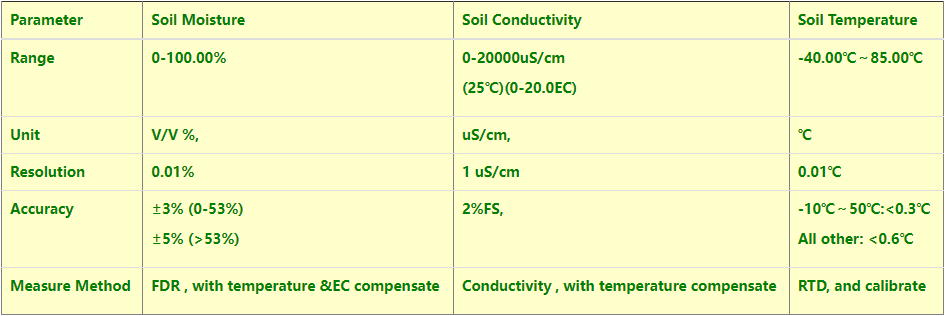
1.3 Specification
Common DC Characteristics:
- Supply Voltage: 2.1v ~ 3.6v
- Operating Temperature: -40 ~ 85°C
NB-IoT Spec:
- - B1 @H-FDD: 2100MHz
- - B3 @H-FDD: 1800MHz
- - B8 @H-FDD: 900MHz
- - B5 @H-FDD: 850MHz
- - B20 @H-FDD: 800MHz
- - B28 @H-FDD: 700MHz
Probe Specification:
Measure Volume: Base on the centra pin of the probe, a cylinder with 7cm diameter and 10cm height.
1.4 Applications
- Smart Agriculture
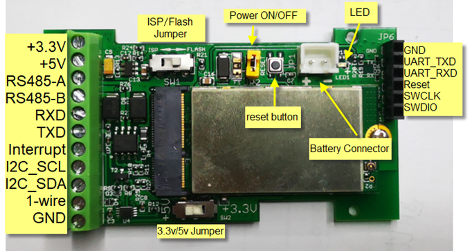
1.5 Pin Definitions
2. Use NSE01 to communicate with IoT Server
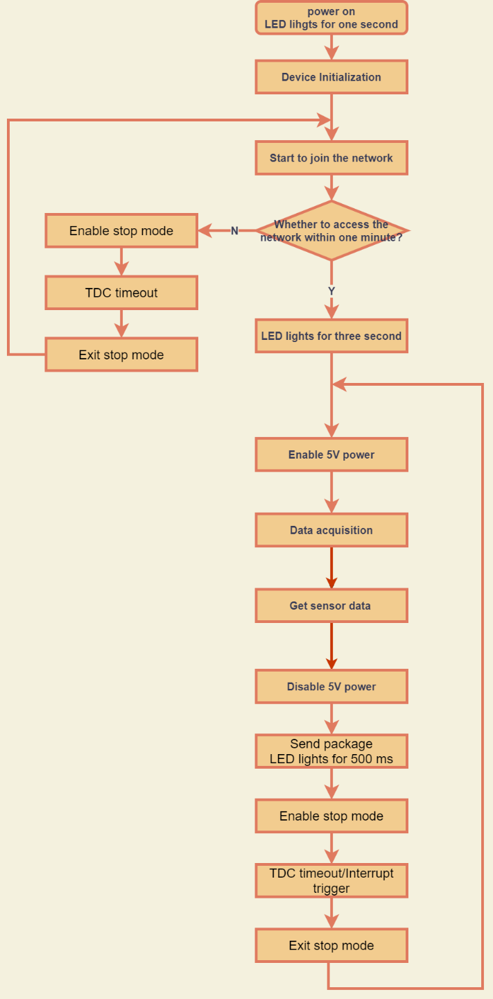
2.1 How it works
The NSE01 is equipped with a NB-IoT module, the pre-loaded firmware in NSE01 will get environment data from sensors and send the value to local NB-IoT network via the NB-IoT module. The NB-IoT network will forward this value to IoT server via the protocol defined by NSE01.
The diagram below shows the working flow in default firmware of NSE01:
2.2 Configure the NSE01
2.2.1 Test Requirement
To use NSE01 in your city, make sure meet below requirements:
- Your local operator has already distributed a NB-IoT Network there.
- The local NB-IoT network used the band that NSE01 supports.
- Your operator is able to distribute the data received in their NB-IoT network to your IoT server.
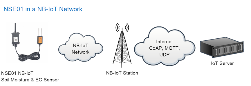
Below figure shows our testing structure. Here we have NB-IoT network coverage by China Mobile, the band they use is B8. The NSE01 will use CoAP(120.24.4.116:5683) or raw UDP(120.24.4.116:5601) or MQTT(120.24.4.116:1883)or TCP(120.24.4.116:5600)protocol to send data to the test server
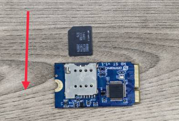
2.2.2 Insert SIM card
Insert the NB-IoT Card get from your provider.
User need to take out the NB-IoT module and insert the SIM card like below:
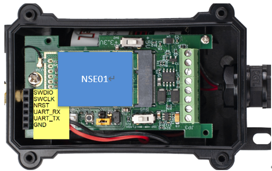
2.2.3 Connect USB – TTL to NSE01 to configure it
User need to configure NSE01 via serial port to set the Server Address / Uplink Topic to define where and how-to uplink packets. NSE01 support AT Commands, user can use a USB to TTL adapter to connect to NSE01 and use AT Commands to configure it, as below.
Connection:
USB TTL GND <----> GND
USB TTL TXD <----> UART_RXD
USB TTL RXD <----> UART_TXD
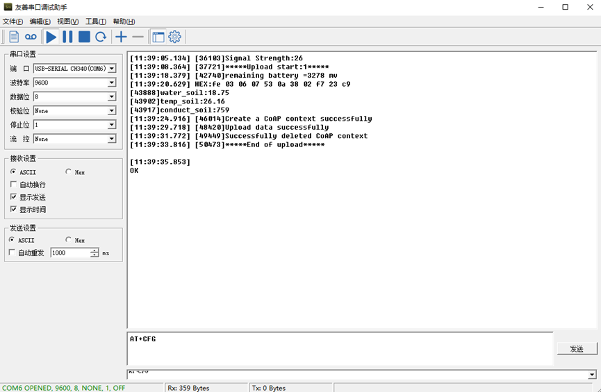
In the PC, use below serial tool settings:
- Baud: 9600
- Data bits: 8
- Stop bits: 1
- Parity: None
- Flow Control: None
Make sure the switch is in FLASH position, then power on device by connecting the jumper on NSE01. NSE01 will output system info once power on as below, we can enter the password: 12345678 to access AT Command input.
Note: the valid AT Commands can be found at: http://www.dragino.com/downloads/index.php?dir=NB-IoT/NSE01/
2.2.4 Use CoAP protocol to uplink data
Note: if you don't have CoAP server, you can refer this link to set up one: http://wiki.dragino.com/xwiki/bin/view/Main/Set%20up%20CoAP%20Server/
Use below commands:
- AT+PRO=1 // Set to use CoAP protocol to uplink
- AT+SERVADDR=120.24.4.116,5683 // to set CoAP server address and port
- AT+URI=5,11,"mqtt",11,"coap",12,"0",15,"c=text1",23,"0" //Set COAP resource path
For parameter description, please refer to AT command set
After configure the server address and reset the device (via AT+ATZ ), NSE01 will start to uplink sensor values to CoAP server.
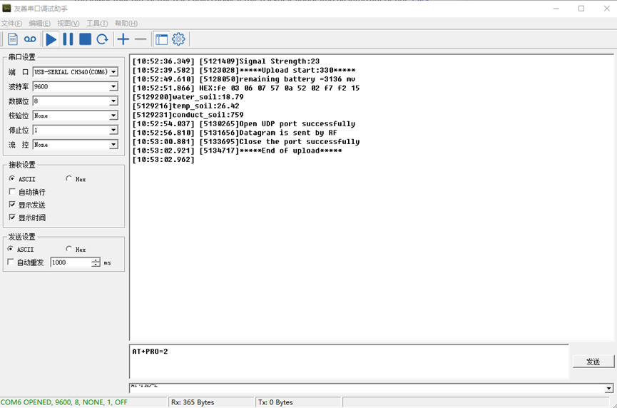
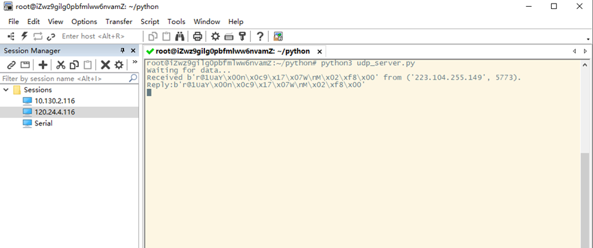
2.2.5 Use UDP protocol to uplink data(Default protocol)
This feature is supported since firmware version v1.0.1
- AT+PRO=2 // Set to use UDP protocol to uplink
- AT+SERVADDR=120.24.4.116,5601 // to set UDP server address and port
- AT+CFM=1 //If the server does not respond, this command is unnecessary
2.2.6 Use MQTT protocol to uplink data
This feature is supported since firmware version v110
- AT+PRO=3 //Set to use MQTT protocol to uplink
- AT+SERVADDR=120.24.4.116,1883 //Set MQTT server address and port
- AT+CLIENT=CLIENT //Set up the CLIENT of MQTT
- AT+UNAME=UNAME //Set the username of MQTT
- AT+PWD=PWD //Set the password of MQTT
- AT+PUBTOPIC=NSE01_PUB //Set the sending topic of MQTT
- AT+SUBTOPIC=NSE01_SUB //Set the subscription topic of MQTT
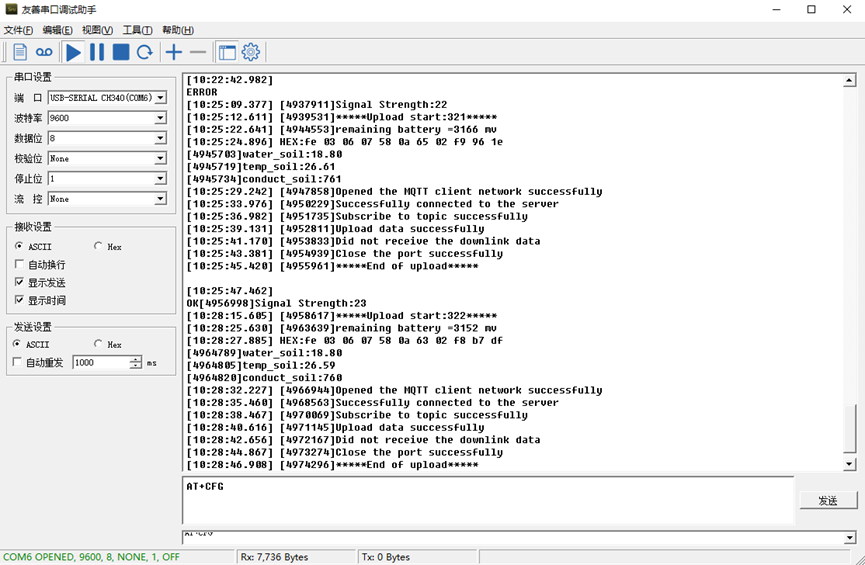
MQTT protocol has a much higher power consumption compare vs UDP / CoAP protocol. Please check the power analyze document and adjust the uplink period to a suitable interval.
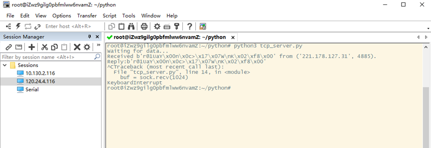
2.2.7 Use TCP protocol to uplink data
This feature is supported since firmware version v110
- AT+PRO=4 // Set to use TCP protocol to uplink
- AT+SERVADDR=120.24.4.116,5600 // to set TCP server address and port
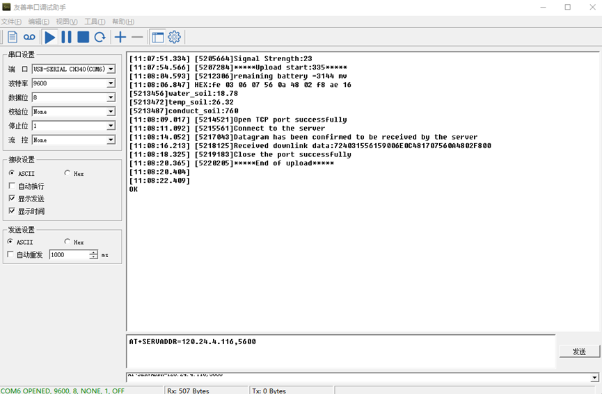
2.2.8 Change Update Interval
User can use below command to change the uplink interval.
- AT+TDC=600 // Set Update Interval to 600s
NOTE:
1. By default, the device will send an uplink message every 1 hour.
2.3 Uplink Payload
In this mode, uplink payload includes in total 18 bytes
Size(bytes) | 6 | 2 | 2 | 1 | 2 | 2 | 2 | 1 |
|---|---|---|---|---|---|---|---|---|
| Value | Device ID | Ver | BAT | Signal Strength | Soil Moisture | Soil Temperature | Soil Conductivity(EC) | Interrupt |
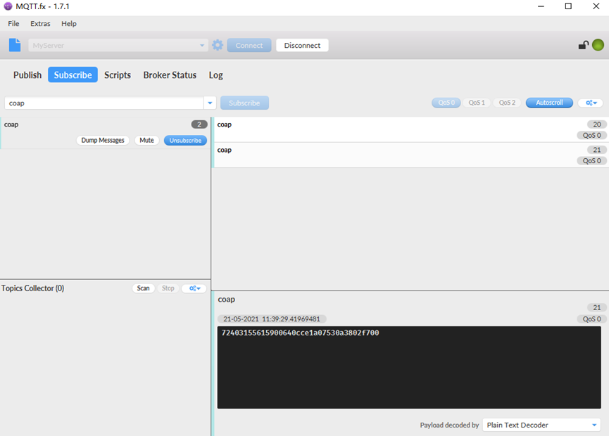
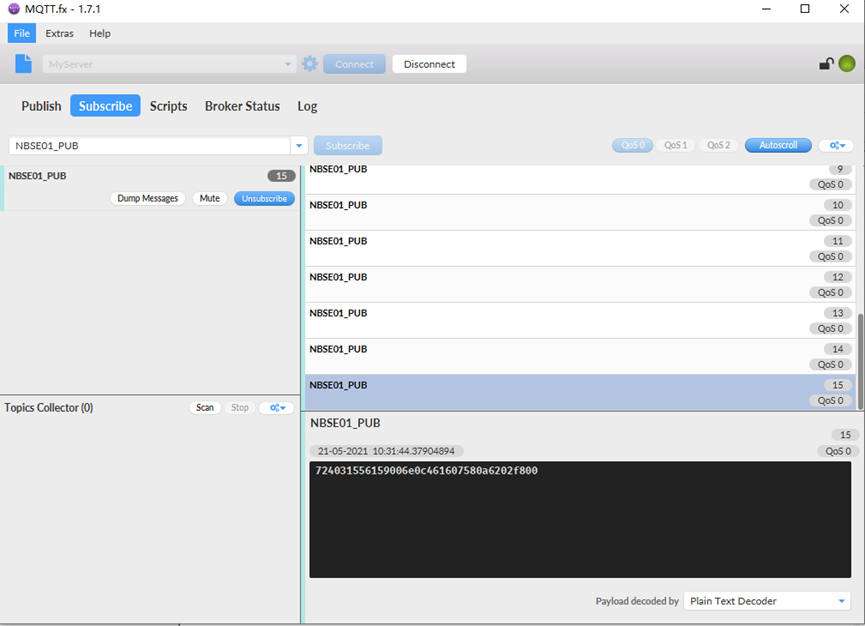
If we use the MQTT client to subscribe to this MQTT topic, we can see the following information when the NSE01 uplink data.
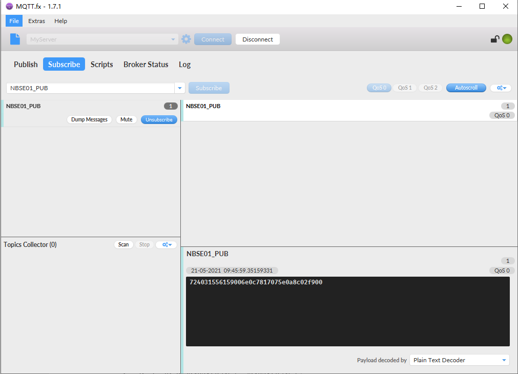
The payload is ASCII string, representative same HEX:
0x72403155615900640c7817075e0a8c02f900 where:
- Device ID: 0x 724031556159 = 724031556159
- Version: 0x0064=100=1.0.0
- BAT: 0x0c78 = 3192 mV = 3.192V
- Singal: 0x17 = 23
- Soil Moisture: 0x075e= 1886 = 18.86 %
- Soil Temperature:0x0a8c =2700=27 °C
- Soil Conductivity(EC) = 0x02f9 =761 uS /cm
- Interrupt: 0x00 = 0
2.4 Payload Explanation and Sensor Interface
2.4.1 Device ID
By default, the Device ID equal to the last 6 bytes of IMEI.
User can use AT+DEUI to set Device ID
Example:
AT+DEUI=A84041F15612
The Device ID is stored in a none-erase area, Upgrade the firmware or run AT+FDR won't erase Device ID.
2.4.2 Version Info
Specify the software version: 0x64=100, means firmware version 1.00.
For example: 0x00 64 : this device is NSE01 with firmware version 1.0.0.
2.4.3 Battery Info
Check the battery voltage for LSE01.
Ex1: 0x0B45 = 2885mV
Ex2: 0x0B49 = 2889mV
2.4.4 Signal Strength
NB-IoT Network signal Strength.
Ex1: 0x1d = 29
0 -113dBm or less
1 -111dBm
2...30 -109dBm... -53dBm
31 -51dBm or greater
99 Not known or not detectable
2.4.5 Soil Moisture
Get the moisture content of the soil. The value range of the register is 0-10000(Decimal), divide this value by 100 to get the percentage of moisture in the soil.
For example, if the data you get from the register is 0x05 0xDC, the moisture content in the soil is
05DC(H) = 1500(D) /100 = 15%.
2.4.6 Soil Temperature
Get the temperature in the soil. The value range of the register is -4000 - +800(Decimal), divide this value by 100 to get the temperature in the soil. For example, if the data you get from the register is 0x09 0xEC, the temperature content in the soil is
Example:
If payload is 0105H: ((0x0105 & 0x8000)>>15 === 0),temp = 0105(H)/100 = 2.61 °C
If payload is FF7EH: ((FF7E & 0x8000)>>15 ===1),temp = (FF7E(H)-FFFF(H))/100 = -1.29 °C
2.4.7 Soil Conductivity (EC)
Obtain soluble salt concentration in soil or soluble ion concentration in liquid fertilizer or planting medium. The value range of the register is 0 - 20000(Decimal)( Can be greater than 20000).
For example, if the data you get from the register is 0x00 0xC8, the soil conductivity is 00C8(H) = 200(D) = 200 uS/cm.
Generally, the EC value of irrigation water is less than 800uS / cm.
2.4.8 Digital Interrupt
Digital Interrupt refers to pin GPIO_EXTI, and there are different trigger methods. When there is a trigger, the NSE01 will send a packet to the server.
The command is:
AT+INTMOD=3 //(more info about INMOD please refer AT Command Manual).
The lower four bits of this data field shows if this packet is generated by interrupt or not. Click here for the hardware and software set up.
Example:
0x(00): Normal uplink packet.
0x(01): Interrupt Uplink Packet.
2.4.9 +5V Output
NSE01 will enable +5V output before all sampling and disable the +5v after all sampling.
The 5V output time can be controlled by AT Command.
AT+5VT=1000
Means set 5V valid time to have 1000ms. So the real 5V output will actually have 1000ms + sampling time for other sensors.
2.5 Downlink Payload
By default, NSE01 prints the downlink payload to console port.
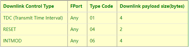
Examples:
Set TDC
If the payload=0100003C, it means set the END Node's TDC to 0x00003C=60(S), while type code is 01.
Payload: 01 00 00 1E TDC=30S
Payload: 01 00 00 3C TDC=60S
Reset
If payload = 0x04FF, it will reset the NSE01
- INTMOD
Downlink Payload: 06000003, Set AT+INTMOD=3
2.6 LED Indicator
The NSE01 has an internal LED which is to show the status of different state.
- When power on, NSE01 will detect if sensor probe is connected, if probe detected, LED will blink four times. (no blinks in this step is no probe)
- Then the LED will be on for 1 second means device is boot normally.
- After NSE01 join NB-IoT network. The LED will be ON for 3 seconds.
- For each uplink probe, LED will be on for 500ms.
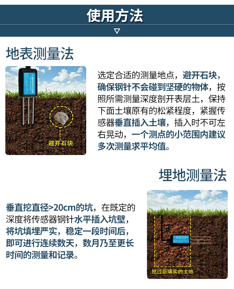
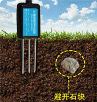
2.7 Installation in Soil
Measurement the soil surface
Choose the proper measuring position. Avoid the probe to touch rocks or hard things. Split the surface soil according to the measured deep. Keep the measured as original density. Vertical insert the probe into the soil to be measured. Make sure not shake when inserting. https://img.alicdn.com/imgextra/i3/2005165265/O1CN010rj9Oh1olPsQxrdUK_!!2005165265.jpg
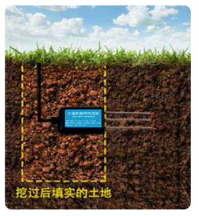
Dig a hole with diameter > 20CM.
Horizontal insert the probe to the soil and fill the hole for long term measurement.
2.8 Firmware Change Log
Download URL & Firmware Change log
www.dragino.com/downloads/index.php?dir=NB-IoT/NSE01/Firmware/
Upgrade Instruction: Upgrade_Firmware
2.9 Battery Analysis
2.9.1 Battery Type
The NSE01 battery is a combination of an 8500mAh Li/SOCI2 Battery and a Super Capacitor. The battery is none-rechargeable battery type with a low discharge rate (<2% per year). This type of battery is commonly used in IoT devices such as water meter.
The battery is designed to last for several years depends on the actually use environment and update interval.
The battery related documents as below:
2.9.2
Dragino battery powered product are all runs in Low Power mode. We have an update battery calculator which base on the measurement of the real device. User can use this calculator to check the battery life and calculate the battery life if want to use different transmit interval.
Instruction to use as below:
Step 1: Downlink the up-to-date DRAGINO_Battery_Life_Prediction_Table.xlsx from:
https://www.dragino.com/downloads/index.php?dir=LoRa_End_Node/Battery_Analyze/
Step 2: Open it and choose
- Product Model
- Uplink Interval
- Working Mode
And the Life expectation in difference case will be shown on the right.
2.9.3 Battery Note
The Li-SICO battery is designed for small current / long period application. It is not good to use a high current, short period transmit method. The recommended minimum period for use of this battery is 5 minutes. If you use a shorter period time to transmit LoRa, then the battery life may be decreased.
2.9.4 Replace the battery
The default battery pack of NSE01 includes a ER26500 plus super capacitor. If user can't find this pack locally, they can find ER26500 or equivalence without the SPC1520 capacitor, which will also work in most case. The SPC can enlarge the battery life for high frequency use (update period below 5 minutes).
3. Using the AT Commands
3.1 Access AT Commands
LSE01 supports AT Command set in the stock firmware. You can use a USB to TTL adapter to connect to LSE01 for using AT command, as below.

Or if you have below board, use below connection:

In the PC, you need to set the serial baud rate to 9600 to access the serial console for LSE01. LSE01 will output system info once power on as below:

Below are the available commands, a more detailed AT Command manual can be found at AT Command Manual: https://www.dropbox.com/sh/qr6vproz4z4kzjz/AAAD48h3OyWrU1hq_Cqm8jIwa?dl=0
AT+<CMD>=?AT+<CMD>? : Help on <CMD>
AT+<CMD>=?AT+<CMD> : Run <CMD>
AT+<CMD>=?AT+<CMD>=<value> : Set the value
AT+<CMD>=?AT+<CMD>=? : Get the value
General Commands
AT : Attention
AT? : Short Help
ATZ : MCU Reset
AT+TDC : Application Data Transmission Interval
Keys, IDs and EUIs management
AT+APPEUI : Application EUI
AT+APPKEY : Application Key
AT+APPSKEY : Application Session Key
AT+DADDR : Device Address
AT+DEUI : Device EUI
AT+NWKID : Network ID (You can enter this command change only after successful network connection)
AT+NWKSKEY : Network Session Key Joining and sending date on LoRa network
AT+CFM : Confirm Mode
AT+CFS : Confirm Status
AT+JOIN : Join LoRa? Network
AT+NJM : LoRa? Network Join Mode
AT+NJS : LoRa? Network Join Status
AT+RECV : Print Last Received Data in Raw Format
AT+RECVB : Print Last Received Data in Binary Format
AT+SEND : Send Text Data
AT+SENB : Send Hexadecimal Data
LoRa Network Management
AT+ADR : Adaptive Rate
AT+CLASS : LoRa Class(Currently only support class A
AT+DCS : Duty Cycle Setting
AT+DR : Data Rate (Can Only be Modified after ADR=0)
AT+FCD : Frame Counter Downlink
AT+FCU : Frame Counter Uplink
AT+JN1DL : Join Accept Delay1
AT+JN2DL : Join Accept Delay2
AT+PNM : Public Network Mode
AT+RX1DL : Receive Delay1
AT+RX2DL : Receive Delay2
AT+RX2DR : Rx2 Window Data Rate
AT+RX2FQ : Rx2 Window Frequency
AT+TXP : Transmit Power
AT+ MOD : Set work mode
Information
AT+RSSI : RSSI of the Last Received Packet
AT+SNR : SNR of the Last Received Packet
AT+VER : Image Version and Frequency Band
AT+FDR : Factory Data Reset
AT+PORT : Application Port
AT+CHS : Get or Set Frequency (Unit: Hz) for Single Channel Mode
AT+CHE : Get or Set eight channels mode, Only for US915, AU915, CN470
4. FAQ
4.1 How to change the LoRa Frequency Bands/Region?
You can follow the instructions for how to upgrade image.
When downloading the images, choose the required image file for download.
How to set up LSE01 to work in 8 channel mode By default, the frequency bands US915, AU915, CN470 work in 72 frequencies. Many gateways are 8 channel gateways, and in this case, the OTAA join time and uplink schedule is long and unpredictable while the end node is hopping in 72 frequencies.
You can configure the end node to work in 8 channel mode by using the AT+CHE command. The 500kHz channels are always included for OTAA.
For example, in US915 band, the frequency table is as below. By default, the end node will use all channels (0~71) for OTAA Join process. After the OTAA Join, the end node will use these all channels (0~71) to send uplink packets.
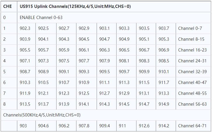
When you use the TTN network, the US915 frequency bands use are:
- 903.9 - SF7BW125 to SF10BW125
- 904.1 - SF7BW125 to SF10BW125
- 904.3 - SF7BW125 to SF10BW125
- 904.5 - SF7BW125 to SF10BW125
- 904.7 - SF7BW125 to SF10BW125
- 904.9 - SF7BW125 to SF10BW125
- 905.1 - SF7BW125 to SF10BW125
- 905.3 - SF7BW125 to SF10BW125
- 904.6 - SF8BW500
Because the end node is now hopping in 72 frequency, it makes it difficult for the devices to Join the TTN network and uplink data. To solve this issue, you can access the device via the AT commands and run:
- AT+CHE=2
- ATZ
to set the end node to work in 8 channel mode. The device will work in Channel 8-15 & 64-71 for OTAA, and channel 8-15 for Uplink.
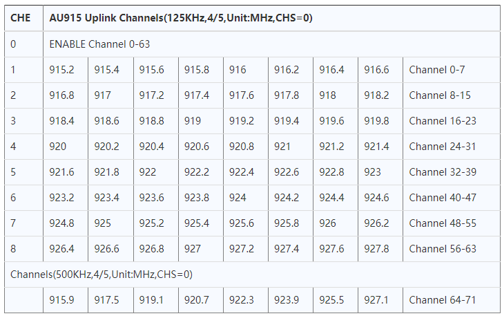
The AU915 band is similar. Below are the AU915 Uplink Channels.
4.2 Can I calibrate LSE01 to different soil types?
LSE01 is calibrated for saline-alkali soil and loamy soil. If users want to use it for other soil, they can calibrate the value in the IoT platform base on the value measured by saline-alkali soil and loamy soil. The formula can be found at this link.
5. Trouble Shooting
5.1 Why I can't join TTN in US915 / AU915 bands?
It is due to channel mapping. Please see the Eight Channel Mode section above for details.
5.2 AT Command input doesn't work
In the case if user can see the console output but can't type input to the device. Please check if you already include the ENTER while sending out the command. Some serial tool doesn't send ENTER while press the send key, user need to add ENTER in their string.
5.3 Device rejoin in at the second uplink packet
Issue describe as below:
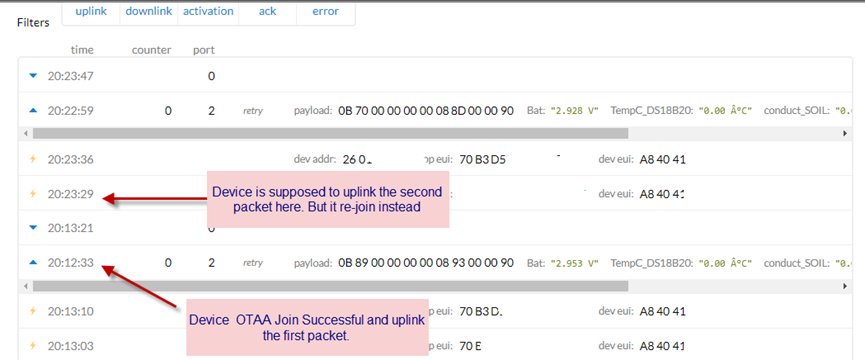
Cause for this issue:
The fuse on LSE01 is not large enough, some of the soil probe require large current up to 5v 800mA, in a short pulse. When this happen, it cause the device reboot so user see rejoin.
Solution:
All new shipped LSE01 after 2020-May-30 will have this to fix. For the customer who see this issue, please bypass the fuse as below:

6. Order Info
Part Number: LSE01-XX-YY
XX: The default frequency band
- AS923: LoRaWAN AS923 band
- AU915: LoRaWAN AU915 band
- EU433: LoRaWAN EU433 band
- EU868: LoRaWAN EU868 band
- KR920: LoRaWAN KR920 band
- US915: LoRaWAN US915 band
- IN865: LoRaWAN IN865 band
- CN470: LoRaWAN CN470 band
YY: Battery Option
- 4: 4000mAh battery
- 8: 8500mAh battery
7. Packing Info
Package Includes:
LSE01 LoRaWAN Soil Moisture & EC Sensor x 1
Dimension and weight:
Device Size: cm
Device Weight: g
Package Size / pcs : cm
Weight / pcs : g
8. Support
- Support is provided Monday to Friday, from 09:00 to 18:00 GMT+8. Due to different timezones we cannot offer live support. However, your questions will be answered as soon as possible in the before-mentioned schedule.
- Provide as much information as possible regarding your enquiry (product models, accurately describe your problem and steps to replicate it etc) and send a mail to support@dragino.com